Experience with Trigger Electronics for the CSC System of CMS J. Hauser1, D. Acosta3, E. Boyd1, B. Bylsma4, R. Cousins1, A. Drozdetski3, S. Durkin4, J. Gilmore4, J. Gu4, S. Haapanen1, A. Korytov3, S. Lee2, T. Ling4, A. Madorsky3, M. Matveev2, M. Mey1, B. Mohr1, J. Mumford1, P. Padley2, G. Pawloski2, J. Roberts2, B. Scurlock3, H. Stoeck3, V. Valuev1, G. Veramendi2, J. Werner1, Y. Zheng1 1
University of California Los Angeles, 2 Rice University, Houston, Texas, 3University of Florida, Gainesville, Florida, 4Ohio State University, Columbus, Ohio;
[email protected]
Abstract Cathode strip chambers are used in the endcap muon detection system of CMS. An extensive set of electronics has been developed for triggering and readout of this system. Electronics associated with each chamber forms trigger muon stubs or “primitives.” The trigger determines the approximate momentum of muons by track finder electronics that link the muon primitives between chambers in several muon stations. The system contains 468 chambers, 217,728 cathode channels and 183,168 anode channels. The on-chamber electronics have been built and are now being installed. The off-chamber electronics are in full production, and their hardware design is complete. Extensive testing of the CSC trigger electronics has been carried out using cosmic rays and test beams. Results from data taken at a test beam at CERN during the summer of 2003 will be presented; particularly those that illustrate the performance of the muon trigger primitive electronics.
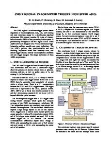
Figure 1: CMS detector cross-section, with the endcap muon system circled (chambers shown in red, iron absorber in yellow).
I. INTRODUCTION The endcap muon system of CMS contains 468 cathodestrip (CSC) detectors covering 1.0-2.4 in rapidity, as shown in Figure 1. The general plans for reading out and triggering with this system have been previously described [1]. Prototypes of on-chamber electronics for this system were previously studied extensively [2] in preparation for their mass-production. The CSC on-chamber electronics production is now complete, and these electronics have now been installed on the CSC chambers. However, the performance of the associated off-chamber electronics needs to be extensively checked as well before their mass production begins. Most of the off-chamber electronics will be housed in 60 VME 9U-size ``peripheral'' crates mounted around the periphery of the endcap muon iron disks. The notable feature of a CSC is excellent position resolution perpendicular to the cathode strips by precision cathode charge readout and interpolation. The CMS endcap muon chambers contain variable-width cathode strips running radially and nearly perpendicular (constant-r) anode wires, as shown in Figure 2. This matches the solenoidal magnetic field, which causes endcap muons of finite momentum to primarily bend in the φ coordinate. In the r-z plane measured by the anode wires, endcap muons travel in nearly straight lines.
Figure 2: Diagram and principle of operation of a CSC endcap muon chamber in CMS.
During the summer of 2003, a CERN test beam with LHC-like time structure was used to test the CSC electronics system including near-final prototypes of all of the peripheral crate electronics. Key goals for this test beam were: to demonstrate that the CSC on-chamber and peripheral crate electronics work well together and with the CSC chambers as a system, to trigger on and read out data for muons with high efficiency and good position resolution, to correctly identify the LHC bunch crossing with high probability, and to handle
ALCT [2] (Anode Local Charged Track): There is one ALCT board on each CSC chamber. The ALCT timealigns anode hits from the AFEBs with the LHC synchronous clock. It then finds patterns among the six layers of anode hits that look like a muon stub and not background neutron-induced hits, noise, etc. Although the drift time in the CSC chambers can take up to 3 bx, the ALCT determines the precise bunch crossing (bx) of the muon using a multiple-layer coincidence timing technique. Up to two anode LCT hit patterns (also called ALCTs) are sent to the TMB. For data readout initiated by an L1A, a block containing the trigger hit patterns and a time history of the anode raw hits is sent to the TMB.
TMB [2] (Trigger Mother Board): A fast pre-trigger initiates data storage on the CFEBs via the DMB (see below), then detailed parameters (position, angle) are found for up to two cathode trigger patterns (CLCTs) for triggering. The CLCTs are brought into time coincidence over several bx (typically 3) with ALCT patterns. If a coincidence is found, the TMB combines the trigger information and sends the two best matched LCTs to the MPC using the more precise ALCT bx. For data readout initiated by an L1A, the TMB passes the anode ALCT information directly to a FIFO in the DMB, and sends in parallel a block containing CLCT patterns, a time history of the cathode comparator raw hits, and anode-cathode coincidence information to the DMB.
MPC [2] (Muon Port Card): Collects LCTs from each of up to nine TMBs in a trigger sector and chooses the best three based on the muon stub quality. Sends this information to the CSC track finder system Sector Processor (SP) board over high-speed optical links.
CFEB [1, 5, 6] (Cathode Front-End Board): Contains sensitive cathode amplifiers and creates parallel data and trigger data paths. The rise and fall times of the amplifiers are 125 ns and 250 ns, respectively. In the precision data path, analog charge information is stored in a switched capacitor array upon receiving a CLCT pretrigger signal (see the TMB description) and then digitized for readout upon receipt of a Level-1 trigger accept (L1A) signal. The digitized charge data are then sent to the DMB. For the trigger data path, custom comparator ASICs find clusters above a programmable threshold, and find the muon position on each CSC layer to a precision of one half-strip by comparing cathode signals on adjacent strips [7]. Results of those comparisons are sent to the TMB board. Each CFEB is attached to 96 cathode strips, and there are 3-5 CFEBs per CSC chamber, depending on the type of chamber.
CCB [9] (Clock and Control Board): Provides the interface of the CSC system with the Trigger, Timing and Control (TTC) system [10] of CMS. Distributes necessary signals for synchronized operation of a peripheral crate.
DMB [1] (Data acquisition Mother Board): Controls all of the CFEB boards on a chamber. Upon arrival of L1A, the DMB collects ALCTs, CLCTs and cathode strip charge data from TMB and CFEB boards, and sends this information serially to the DDU.
DDU [1] (Detector-Dependant Unit): Upon arrival of L1A, collects data from all DMBs in a CSC sector and sends the information through the global DAQ path. The DDU was read out via Gigabit Ethernet to a PCI card, and from there to disk on a Linux computer.
AFEB [8] (Anode Front-End Board): Contains a single 16-channel amplifier plus constant-fraction discriminator ASIC with a programmable threshold. The hits are sent to the ALCT board. There are up to 42 AFEBs per CSC chamber.
In addition to the previous modules, a prototype track finder SP (Sector Processor) board [11] was used at the 2003 test beam to receive trigger signals on optical fibers from the MPC board and store them in a 256-deep FIFO for readout through a VME interface.
the maximum particle rates expected at LHC. describes the results of those beam tests.
This note
A schematic of the CSC on-chamber and peripheral crate electronics system is shown in Figure 3. For each CSC chamber, the on-chamber electronics is connected to one pair of boards in a peripheral crate: a Trigger MotherBoard (TMB) module and a Data acquisition MotherBoard (DMB) module. Each crate services one trigger sector, i.e. 60o in muon stations 2-4 and 30o in muon station 1. A peripheral crate has 9 TMB/DMB board pairs, each of which serves one CSC chamber. Trigger data from each sector is collected by the Muon Port Card (MPC) and sent by optical fiber to the CSC track finder.
Figure 3: Schematic of the on-chamber and peripheral crate electronics system.
A short explanation of the function of each of the modules that are shown in Figure 3 follows:
II. TEST BEAM SETUP The CSC setup shown in Figure 4 was placed in the X5A test beam, which is a horizontal tertiary beam from CERN's SPS (400 GeV/c), providing muon and pion beams with energy between 5 and 250 GeV. Collimators in the beam line allowed for control of the rate of particles. An important feature of the muon and pion beams during part of the running time was a 25 ns bunch structure similar to that of the LHC, with 48 bunches filled out of the SPS orbit cycle of 924 RF buckets (the LHC has 3564 bunches). Particles were extracted during a 1.5-2.5 s spill out of a 16.8 s ramp cycle. Within each 25ns bunch, particles arrived during a window 2.3 ns wide. Muon rates up to 104 per spill and pion rates up to 106 per spill were available.
peripheral crate data offline using the common Level-1 trigger accept (L1A) number distributed via the TTC.
III.
ALCT ALGORITHM AND RESULTS
A. ALCT Algorithm The ALCT board computes the number of layers hit each bunch crossing for each wire group on “key” layer 2 of the chamber simultaneously within “Collision” and “Accelerator” envelopes shown in Figure 5. A typical trigger sequence begins with a “pretrigger” if the number of layers hit within a pattern is ≥2, upon which there is a delay (typically 1 bx), and a trigger is found if the number of layers then is ≥4. The minimum number of layers for pretrigger and trigger are selectable between 1 and 6. If multiple ALCT muon stubs are found simultaneously in a chamber, they are ranked by i) the largest number of layers hit, and ii) collision-type stubs are preferred over accelerator-type muon stubs.
Figure 5: ALCT trigger patterns used. Accelerator muon patterns can be used to veto a chamber in case that CMS suffers a high rate of accelerator-related background muons of high momentum traveling nearly parallel to the beam axis. Figure 4: A diagram of the 2003 CSC test beam setup.
Two CSCs were equipped with production on-chamber electronics and connected to near-final prototype off-chamber electronics. The two CSCs were placed with their long dimensions horizontal. The chambers were nominally 1.25 m apart with their normal vectors oriented horizontally and rotated 20o from the beam axis, so that the beam represented a CMS muon at θ=20o and infinite momentum. The trigger electronics was set to form triggers from internal chamber information, but the initiation of readout was initiated by a three-fold coincidence of signals from 10 cm by 10 cm scintillator paddles of the beam hodoscope. The hodoscope thus determined the precise timing standard to which the CSC data was compared. The background rate of non-particle coincidences from this hodoscope was so low as to be unmeasured. A data block was created for every scintillator hodoscope coincidence in order to obtain true efficiency measurements even if no CSC information was read out. A number of synchronization steps were then performed. Fine adjustments were made to clock phases for 40 MHz CFEB-TMB and 80 MHz ALCT-TMB and TMB-MPC data transmissions. Course adjustments in 25 ns steps were made for ALCT-CLCT trigger coincidence, and for L1A to initiate readout of CFEB, ALCT, and TMB data FIFOs. A common TTC [10] system was used for both SP and peripheral crates, and SP data read out through VME was synchronized to
B. ALCT Results The ALCT board latches anode data synchronously using a clock whose phase relative to the passage of the muons through the chambers is a priori unknown. To adjust this phase, the anode data is delayed on the ALCT by a variable amount in 2 ns step delays until the muon stub data is found maximally in one single bx. The delay curves are shown in Figure 6. The time delays are then set to the settings which yield the maximum efficiency: 98.2% for chamber 1 at a delay of 22 ns, and 98.0% on chamber 2 for a delay of 11 ns.
Figure 6: ALCT delay scan results. The x-axis is the ALCT fine delay setting for input anode hits, and the y-axis is the fraction of anode muon stubs arriving in the bunch crossing containing the most stubs.
Figure 7 (bottom) shows the resulting distribution of bunch crossings found by the ALCT boards. The top
histograms show the corresponding cathode stub (CLCT) time distributions. The anodes yield better timing because the anode signals are larger and the AFEB amplifiers are faster, and additionally because no fine time adjustments are made to the latching of cathode data within the 25 ns clock. It is apparent from the plots that about 1% of CLCTs can be lost if they are time-matched with ALCTs over a 3-bx time window rather than a 5-bx window.
C. CLCT Results CLCT stub-finding depends on good comparator performance. This was studied by tracking the muons precisely through the chamber using the precision charge readout of the DMB. A 6-layer fit was performed, and the fitted position was compared to the position of the center of the half-strip identified by the comparator ASIC. The differences in position are shown in Figure 9. If the comparators performed perfectly, one would see a rectangle between -0.25 and +0.25. The distribution is seen to be slightly rounded and asymmetric.
Figure 7: Differences between LCT bunch assignments and those correct one as assigned by the scintillator hodoscope. The plots show CLCT (top) and ALCT (bottom) results for chamber 1 (left) and chamber 2 (right). Note the logarithmic scales.
IV.
CLCT ALGORITHM AND RESULTS V. CLCT ALGORITHM
The TMB receives up to 160 half-strip hits from each of the 6 CSC chamber layers in encoded fashion from the comparator ASICs on the CFEBs. The CLCT-finding algorithm on the TMB board looks simultaneously for highmomentum muons using half-strip bits and low-momentum muons having more bending using “di-strip” bits. The di-strip bits are formed by OR’ing four adjacent half-strip bits. For both high- and low-momentum muons, the numbers of layers hit each bunch crossing is computed for each half- or di-strip on “key” layer 3 of the chamber within envelopes shown in Figure 8. All patterns are searched simultaneously. If the number exceeds a “pre-trigger” threshold such as 2 layers, then a delay (typically 2 bx) is initiated. After the delay, the number of layers has to exceed a threshold such as 4 layers for a CLCT muon stub to be found. If there are multiple CLCTs found, then they are ranked by i) half-strip patterns preferred to di-strip patterns, ii) the number of layers hit, and iii) the pattern number (straightest=best).
Figure 8: CLCT trigger patterns used.
Figure 9: Comparator resolution: the number of entries is plotted as a function of the difference between the fitted track and the center of the half-strip found by the comparator chip.
To determine whether a track has passed on the right or the left side of a strip, the comparator ASIC contains a analog comparison of voltages from left and right neighbor strips. Again using the precision charge readout, the probability of seeing the comparator yield a hit on the right side is plotted as a function of the charge difference between neighbor strips in Figure 10. One sees an offset of about 5 fC which is somewhat larger than the RMS width of the error function (3 fC).
Figure 10: The probability that the comparator registers the hit on the right side of a strip versus the charge difference between the left and right neighbor strips (0.56 fC/ADC count).
The performance of the comparators also depends on cluster charge. Clusters with larger total charge will have larger average charge differences so that the comparator decisions will be more often correct. However, for very large charges, amplifier saturation can degrade the comparisons. Both effects - deterioration of performance at very small charges and also at very large charges - are seen in Figure 11. The CMS endcap muon CSC chambers are designed to operate with average cluster charges of about 100 fC, near the maximum efficiency point of the curves. Together with the redundancy afforded by a 6-layer coincidence, the performance is certainly adequate.
Figure 12: Efficiency to find a CLCT as a di-strip or a halfstrip pattern (and the total efficiency) as a function of the chamber tilt angle.
Figure 11: Efficiency to find the correct position versus cluster charge. From bottom to top, the sets of points represents finding the exactly correct half-strip, the correct full strip, and either the exactly correct half-strip or an adjacent (±1) half-strip.
The CLCT-finding efficiency and pattern occupancy were studied as functions of the tilt angle of the chambers, which mimics the various angles of incidence of muons of various momenta in CMS. The CLCT-finding efficiency and the breakdown into half-strip and di-strip categories are shown in Figure 12. The overall efficiency is nearly flat at 99.8%. Halfstrip patterns are seen to be highly efficient at small tilt angles, while di-strip patterns are efficient at large tilt angles. A more detailed examination of the patterns found and the number of layers found in the patterns is shown in Figure 13. The data show the expected behavior: at zero degrees tilt, mostly half-strip pattern 4 (straight) is occupied, especially for 6 and 5 layers hit. At 5 degrees, mostly half-strip patterns are found, but the patterns correspond to bends near the CLCT half-strip envelope. At 20 degrees, mostly di-strip and largebend patterns are found.
Figure 13: Occupancy of CLCT pattern type (half- and distrip), pattern numbers, and number of layers for three different chamber tilt angles. “Quality” on the vertical axis is the number of layers hit minus 3. From top to bottom, the data is for chamber tilt angles of 0, 5, and 20 degrees. The left and right plots show relative occupancies of half-strip patterns and di-strip patterns, respectively.
High-rate trigger studies were done using pion beams. Since the rates were too high for full readout, trigger signals and scintillator hodoscope signals were taken directly to scalars. Figures 14 and 15 show the rate of ALCT and CLCT muon stubs as a function of the instantaneous pion beam intensity. (The instantaneous rate is nearly 20 times higher than the average beam intensity since only 48 consecutive bunches were occupied by particles out of the 924 bunches in an orbit). The ALCT rate is entirely linear with beam intensity, while the CLCT rate starts to deviate about 500 KHz. However, the maximum CLCT rate expected from simulations in any chamber is not expected to exceed 100 KHz at full LHC luminosity, and further work on the CLCT algorithm will reduce the small deadtime observed at the highest rates.
VI.
TMB RESULTS
The TMB matches ALCT and CLCT muon stubs within a time window which is typically 5 bx wide (±2), using the more precise ALCT timing to define the muon bx. An absolute measure of the efficiency for a chamber, including this coincidence, was determined by requiring a matched LCT in one chamber and looking for how often a matched LCT was observed in the same position in the other chamber, using the readout from the SP [11]. For a spatial coincidence over ±5 strips and ±3 wire groups, the efficiency was measured as 97.9% for perfect agreement of timing, 98.9% in a 2-bx window, and 99.1% within a 3 bx (±1) wide window.
performance under all conditions. Some aspects of the final system which were not implemented at that time - the transmission of RPC hits to the TMB in station 1 for timing and ambiguity (ghost) resolution in the case of 2 or more muons in a single chamber, and the momentum determination capability of the SP track finder - are being addressed in a 2004 test beam. We may anticipate that the programmability of FPGAs throughout this electronics system will allow for continued performance improvements in the years before the LHC begins data-taking.
VIII.
REFERENCES
[1] The CMS Collaboration, “CMS, the Compact Muon Solenoid. Muon Technical Design Report,” CERN-LHCC-9732, Dec. 1997. [2] The CMS Collaboration, “CMS. The TRIDAS Project. Technical Design Report, Vol. 1: The Trigger Systems,” CERN-LHCC-2000-038, Dec. 2000. [3] D. Acosta et al., “Design Features and Test Results of the CMS Endcap Muon Chambers,” Nucl. Instrum. Meth. A494:504-508, 2002. [4] J. Hauser, “Primitives for the CMS Cathode Strip Muon Trigger,” Snowmass 1999, Electronics for LHC Experiments, 304-308, Sep. 1999. [5] R. Breedon et al., “Results of Radiation Tests of the Cathode Front-End Board for CMS Endcap Muon Chambers,” Nucl. Instrum. Meth. A471:340-347, 2001.
Figure 14: intensity.
Rate of ALCT muon stubs versus pion beam
[6] T.Y. Ling, “Front End Electronics of the CMS Endcap Muon System,” Rome 1998, Electronics for LHC Experiments, 262-266, Sep. 1998. [7] M. Baarmand et al., “Spatial Resolution Attainable With Cathode Strip Chambers at the Trigger Level,” Nucl. Instrum. Meth. A425:92-105, 1999. [8] N. Bondar et al., “Anode Front-End Electronics for the Cathode Strip Chambers of the CMS Endcap Muon Detector,” Stockholm 2001, Electronics for LHC Experiments, 190-194, Sep. 2001. [9] M. Matveev et al., “The Clock and Control Board for the Cathode Strip Chamber Trigger and DAQ Electronics at the CMS Experiment,” Colmar 2002, Electronics for LHC Experiments, 359-362, Sep. 2002. [10] B.G. Taylor for the RD12 Project Collaboration, “TTC Distribution for LHC Detectors,” IEEE Trans. Nucl. Sci. 45:821-828, 1998.
Figure 15: intensity.
Rate of CLCT muon stubs versus pion beam
VII.
SUMMARY
Studies of test beam data taken with production and preproduction electronics of the CSC muon detection system of CMS during the 2003 test beam have shown good
[11] D. Acosta et al., “Performance of a Pre-Production Track-Finding Processor for the Level-1 Trigger of the CMS Endcap Muon System,” these proceeding, 2004.