Transactions of the ASME ... 1 Calculated moment coefficients using infinite cylinder relations ... defined in Table 1 for the three components of velocity. p.eff is .... A-G. 8.78E-03. 8.72E-03. 8.73E-03. 8.75E-03. 118 / Vol. 118, MARCH 1996.
p. M. Wild N. Djilali G. W. Vickers Department of Mechanical Engineering, University of Victoria, Victoria, B. C. Canada V8W 3P6
Experimental and Computational Assessment of Windage Losses in Rotating Machinery A combined experimental and computational investigation of the flow between a rotating cylinder and a fixed enclosure is presented. The configuration considered is related to the design of a centrifugal desalinator, and includes the flow in the annular as well as in the axial gap regions. The computed flowfield shows significant variations in the axial distribution of the azimuthal shear stress due to the secondary flow associated with Taylor vortices. The averaged azimuthal shear stress (or torque) is however not very sensitive to the number of vortices. Computational results also show that, where the aspect ratio of the annulus (rotor length to radial gap width) is relatively small, this azimuthal variation results in a higher average azimuthal shear stress than for the case where the aspect ratio of the annulus is relatively large. Various functional relations for windage torque of infinite cylinders, developed by other researchers on the basis of power law relations or assuming a log-law velocity distribution, are evaluated. Three such relations are found to be in good agreement with the experimental results when coupled with a correction for end effects. These relations are also the most useful with respect to the design of rotating equipment.
Introduction The nature of flow in the annular gap between concentric cylinders, where the inner cylinder is rotating and the outer cylinder is stationary, is of general interest in many engineering applications, including the design of rotating equipment such as turbines, pumps, motors, generators and centrifuges as well as the design of the journal bearings which, in some cases, support these various rotors. The flow characteristics of interest vary with the application. In motor design, heat transfer and frictional losses are the key parameters while, in journal bearings, the pressure distribution and thus the load carrying capability are of particular interest. The authors' interest in this problem stems from the development of a sea water desalination technology. Centrifugal Reverse-Osmosis (CRO) (Wild et al, 1989, 1994), in which a centrifuge rotor is a key component. Windage losses are a significant component of the power consumption of this device and an assessment of the effect alternative design configurations have on these losses is therefore an essential component of the design process. The flow between concentric rotating cylinders has been the subject of numerous studies since the early work of Taylor (1923, 1935) who reported on the transition from laminar Couette flow to laminar Taylor vortex flow, characterized by the formation of an array of toroidal vortices, beyond a critical value of the Reynolds or Taylor number. The spatial frequency of vortices depends on geometric and flow parameters, as well as on the manner of rotor acceleration. At Taylor numbers sufficiently higher than the critical value, instabilities in the form of azimuthal waves develop along the Taylor vortices (Coles, 1965, Fenstermacher et al., 1979, Shultz-Grunow and Hein, 1956). At still higher speeds, the wavy vortices give way to broad band spectrum turbulent flow, in which the vortex structure persists but the azimuthal oscillations are extinguished (Coles, 1965; Fenstermacher et al., 1960). Although extensive
work has been done in this area, general criteria for the critical speed at which these upper transitions occur are not available. As in the Taylor vortex flow regime, both the wavy and turbulent regimes are characterised by nonunique spatial frequencies. Coles' experiments (1965) showed that as many as twenty-six stable spatial states could exist at a given rotor speed. If the rotor is accelerated slowly from rest, there is a preferred spatial frequency called the primary mode. If the manner of rotor acceleration is varied, the resulting spatial frequency may be higher or lower, resulting in what are generally referred to as "anomalous modes" (Benjamin and Mullin, 1981). The non-uniqueness and bifurcation problems related to the determination of the spatial frequency of vortices have been the subject of numerous recent experimental, analytical and numerical studies, most notably by Coles (1965), Benjamin (1978a, 1978b), Mullin (1982), and Cliffe (1989). Functional Relations for iVtonient Coefficient of an Infinite Cylinder. From a practical engineering standpoint, the most important issues are the determination of the nondimensional torque, or moment coefficient C^^.^^ as a function of Reynolds number and annular gap width, and the assessment of end effects. For super critical speeds, the relations in the literature fall into two general categories. Relations falling into the first category assume that the moment coefficient is inversely proportional to the Reynolds number, taken to some power, i.e. C;^„^ocRe-«
It can be shown that the relation for C^^^ for laminar flow is a special case of this category where a = \ (Donnelly and Simon, 1960). Relations falUng into the second category assume that the nature of the drag on the rotating cylinder is fundamentally related to the Prandtl-von Karman logarithmic velocity distributions and are, therefore, characterized by a relation of the form, 1
Contributed by the Fluids Engineering Division for publication in the JOURNAL OF FLUIDS ENGINEERING. Manuscript received by the Fluids Engineering Division November 3, 1994; revised manuscript received August 9, 1995. Associate Technical Editor: L. Nelik.
(1)
4CM
= A + B In
(2)
where A and B are constants.
116 / Vol. 118, MARCH 1996
Transactions of the ASME
Copyright © 1996 by ASME Downloaded 19 Jul 2008 to 142.104.122.131. Redistribution subject to ASME license or copyright; see http://www.asme.org/terms/Terms_Use.cfm
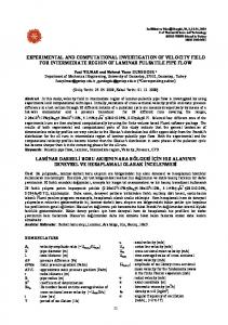
The earliest published relations of the first category were reported in an early experimental study by Wendt (1933), who found that, for supercritical speeds, the moment coefficient varies as Re~°^ for 400 < Re < 1 0 \ and as Re"°^ for Re > 10^ Stuart (1958) developed a relation for the moment coefficient for speeds greater than but close to the critical speed and, based on experimental data, Donelly (1960) used a two parameter expression to recast Stuart's solution to apply over a range of supercritical speeds of up to several hundred times the critical speed. Donelly was able to achieve good fits with measurements from a variety of studies. However, the method is of limited practical use because the empirical parameters need to be determined anew for each configuration. Bilgen and Boulos (1973) also attempted to reassess the functional relationship between torque and Reynolds number, and in fact obtained an expression almost identical to that of Wendt (1933). In a recent paper, Lathrop et al. (1992) used a high resolution torque measurement apparatus to investigate large Reynolds number flow. They found that, in fact, the exponent, a, is not constant, but rather varies continuously over two ranges of Reynolds numbers, and they inferred an abrupt change in the exponent at yet another "critical" Reynolds number. Re-examination of Wendt's data confirmed this discontinuous variation. The earliest relation of the second category was reported by Theodorsen and Regier (1944) who successfully applied the log-law to the open rotating cylinder problem. The enclosed cyUnder problem was first considered by Gazely (1958) followed by Vrancick (1968), Ustimenko (cited in Genium, 1969) and, more recently, by Lathrop (1992). Generally good agreement with experimental data was obtained in all studies. Amongst the relations of both categories, only Wendt, Bilgen and Boulos, Ustimenko and Lathrop include coefficients which are a function of the ratio of the annular gap width to the rotor radius. Only these relations, therefore, have the potential to be applied broadly to a variety of geometries. The moment coefficients calculated from these relations are shown in Fig. 1 for two ratios of radial gap width to rotor radius. With the exception of Lathrop (not plotted), these relations show reasonable agreement over a range of Reynolds numbers. The Finite Cylinder and "End Effects." Most of the work on Taylor flow neglects the effect of the rotor ends by assuming cylinders of infinite length, and relatively few studies have addressed the complications which the rotor ends introduce. The influence of end effects on Taylor vortex formation and transition was first investigated by Cole (1976). He showed that the onset of wavy vortices was relatively sensitive to rotor length whereas the onset of steady Taylor vortices was not. Burkhalter and Koschmieder (1973) showed that the length of the vortex cells at the ends of an annulus was a function of both rotor speed and of the conditions at the ends of the annulus. Schaefer (1980) and Cliffe and Mullin (1985) have conducted
0.008
0.004
0.002
1000
100000
Fig. 1 Calculated moment coefficients using infinite cylinder relations
numerical investigations of the influence of end effects on the stability of anomalous modes. There is, however, no literature which deals directly with the influence of end-gaps on windage torque. In this paper, a combined experimental and numerical study of turbulent Taylor vortex flow is presented. Experiments are conducted for two relatively low ratios of radial gap width to rotor radius. The computational model accounts for both the finite rotor length and end-gaps between the rotor enclosure. Computational Analysis Problem Formulation. The geometry for the rotor-enclosure system is shown in Fig. 2. The flow is assumed to be steady, incompressible and turbulent, and all fluid properties are assumed constant. The flow is also assumed to be axisymmetric, and the problem can therefore be treated as two-dimensional, in the sense that gradients in the azimuthal direction
r - axis
F
E
— i ^ ^ ^ ^^J^^^^^^^ . BHBII t - axis
Fig. 2
Computational domain
Nomenclature CM = moment coefficient due to entire surface of rotor ( = Mc + CjifcYi. ~ moment coefficient due to cylindrical surface of rotor ( = Mc/TrpuJ^RtL) ^'"csc — moment coefficient due to a disc (or rotor ends) ( = Me/Trpoj'-RtL) gr = radial gap ( = 7?„ - /?,) ga = axial gap k = turbulent kinetic energy L - length of rotor Journal of Fluids Engineering
Mc = moment on outer cylindrical surface of rotor Mp = moment on ends of rotor Re = Couette Reynolds number ( = puRigrljj) Ri = inner radius of rotor enclosure Ro = outer radius of rotor = source term in transport equations «T = friction velocity ( = yrjp) y'^ = nondimensional displacement from the wall ( = yujv)
u, V, w = axial, radial and azimuthal velocities X, r, 9, = axial, radial and azimuthal coordinates e = dissipation rate of turbulent kinetic energy Heff = effective viscosity ( = p, + p,) p = dynamic viscosity p, = eddy viscosity p = density of fluid T,„ = shear stress at rotor surface w = angular velocity of rotor
MARCH 1996, Vol. 118 / 117
Downloaded 19 Jul 2008 to 142.104.122.131. Redistribution subject to ASME license or copyright; see http://www.asme.org/terms/Terms_Use.cfm
Table 1
Source terms in momentum equations
0.125' 0.100
dp dx dp ^
-Vr^
vw
V
w' r
-p — -- P'^ff r
'"'''•
V
A*
0.050' 0.025 0.000'
w
-0.025
7
-0050' -0.075' 0.0
are neglected, but all three velocity components are taken into account. With these assumptions, the time-averaged mass and momentum conservation equations may be written as: •^(pu) ox
+ -^iprv) r or
80 X 50 CELLS 1 1 8 X 7 3 CELLS 149 X 96 CELLS
0.075 •
= 0
(3)
0.2
0.4
0.6
0.8
1.0
Fig. 4 Effect of grid refinement on computed radial velocity profile in end-gap region
adjacent to solid boundaries were located such that 30 s {y^ = yujv) < 100.
d d — (prufj)) + — {prv4>) ox or
Numerical Solution and Grid Refinement. The equations were solved using the finite volume code FLUENT (Fluent Inc., 1992). This code uses a collocated grid method. The higher order QUICK discretization scheme was employed in conjunc8^ d4> d_ + S. (4) tion with the SIMPLEC algorithm. A block iterative solution l^eff dx r dr dx method was used together with a multigrid procedure to accelerate convergence. The calculation procedure was terminated where 4> = u,v,w, respectively, for the three momentum equa- when the normalized residuals were less than 5 X 10 "''. The grid tions in the X, r, and 6 directions and S^ is the source term sensitivity of the solutions was assessed at a Couette Reynolds defined in Table 1 for the three components of velocity. p.eff is number of 1.7 X lO'' (corresponding to 5000 rpm). the sum of the laminar viscosity and turbulent eddy viscosity, Grid refinement was conducted in two stages. First computa11^= fi + II,. (5) tions were performed for a non-uniform base grid of 80 X 50, and two successive refinements were performed. The predicted The turbulent eddy viscosity JJL, is obtained from the Prandt- flow field and shear stresses in the radial gap region (CDEF) Kolmogorov relation varied significantly, but the predictions in the axial gap region (ABFG) were essentially identical for the three grids, as shown ^2 PI = C^,p — (6) in Figs. 3 and 4. e Based on these results, a second series of grid refinements where Q is an empirically determined constant and the turbu- was performed in the annular region (DEGH), while keeping lent kinetic energy, k, and its dissipation rate, e, are determined the same 18 X 34 subgrid of the 80 X 50 grid in the axial gap using three alternative models: the standard k-e model (Laun- region (ABCH). The results of this series of grid refinements der and Spalding, 1974), the renormalised group theory (RNG) are summarized in Table 2 in terms of the calculated windage k-e model (Yakhot et al., 1986), and the Reynolds Stress torque for the different surfaces. The streamline patterns obtained with the intermediate grid, shown in Fig. 5, clearly depict Model (Launder et al., 1975). the Taylor vortices in the radial gap and the large counterBoundary Conditions. The governing equations are solved clockwise vortex in the axial gap. The number of vortices obin a computational domain shown in Fig. 2, with the following tained with all three grids was identical, but noticeable differences were observed in the wavelengths, particularly for lower boundary conditions: grid densities, as shown by the axial distribution of the azi(i) At the axis of symmetry, the normal gradients of all muthal shear stresses presented in Fig. 6 ( a ) . When summed variables are set to zero, and the convective flux normal to the along the cylinder, however, the total torque due to this shear boundary is set to zero. stress shows a maximum variation of less than 2 percent from (ii) No slip condition is imposed at all walls for the veloc- the coarsest to the finest grid, as shown in Table 2. This is ity; the equilibrium wall function treatment (Launder and Spal- consistent with Cole (1974) who found that measured torque ding, 1974) is adopted to bridge the viscous sublayer. To ensure was not affected by the number of Taylor vortices occurring at proper implementation of the wall functions, the grid points a given speed. The effect of grid refinement on the radial component of velocity, along the centerline of the radial gap, shows a similar axial distribution, as shown in Fig. 6{b). Again, the variation SOX 50CELLS U8X73CELLS
Table 2 Average torque (N-m) for each wall segment for four grid densities (5000 rpm) Wall segment designations Grid size 0.0
0.2
0.4
0.6
O.S
1.0
r/R, Fig. 3
Effect of grid refinement on computed rotor-end shear stress
118 / Vol. 118, MARCH 1996
109 140 170 230
X X X X
56 56 56 56
B-C
C-D
G-E
A-G
-1.93E-02 -1.93E-02 -1.93E-02 -1.93E-02
-7.60E-02 -7.60E-02 -7.55E-02 -7.48E-02
8.35E-02 8.41E-02 8.38E-02 8.29E-03
8.78E-03 8.72E-03 8.73E-03 8.75E-03
Transactions of thie ASIME
Downloaded 19 Jul 2008 to 142.104.122.131. Redistribution subject to ASME license or copyright; see http://www.asme.org/terms/Terms_Use.cfm
I
WINDAGE TORQUE RESTRAINING ARM ,_STRAIN GAGE
-DRIVE BELT
ROTOR
'
ROTOR ENCLOSURE ROTOR ENCLOSURE
' '
Fig. 7 Schematic view of experimental apparatus
Fig. 5 Computed streamline patterns in tlie annular and end-gap regions
in wavelengths is noticeable from grid to grid. Also note that the amplitude of the radial velocity component is not negligible, as would be assumed in one-dimensional flow, and is on the order of 7.5 percent of the tangential velocity of the rotating cylinder. Based on the relative grid-independence of the calculated torques, the intermediate grid, 140 X 56 was selected for parametric studies of the effects of Reynolds number, radial gap width and rotor length.
Experimental Apparatus and Procedure An experimental test rig was designed and built, consisting of a drive motor connected via a belt drive to a cantilevered
cylindrical rotor, housed in a stationary cylindrical enclosure, as shown in Fig. 7. The rotor enclosure is mounted on bearings at either end, and it is restrained from rotating by a length of 0.125 X 1 inch aluminumflatbar. For future work, the enclosure bearings are mounted on vertical and horizontal slides which allow the enclosure to be set eccentric to the rotor. The reaction torque of the rotor enclosure due to windage is measured via strain gages on the flat bar. The dimensions of the rotor and rotor enclosure were determined from similarity considerations with respect to proposed desalinator designs and are shown in Table 3. The maximum operating speed of the rotor was 4750 rpm. The surfaces of the rotor and enclosure are machined to approximately 32 microinches of roughness. Torque data was taken repeatedly at 500 rpm intervals and the resulting moment coefficients were determined to have an uncertainty interval of ±0.00012 (odds of 20 to 1). Discussion Comparison of Windage Data Determined From Functional Relations, CFD Analysis, and Experiments. The moment coefficients computed using the k-e model are compared to measured data and to the relations of Wendt (1933), Bilgen and Boulos (1973), and Ustimenko (cited in Genium, 1969) in Figs. 8(a) and {b). Since these relations are for infinite cylinders, a correction for end effects was added. Following Schlichting (1960), the additional torque due to end effects is assumed to be equal to that of an enclosed thin disk. The experimental data for g^IRi = 0.0275 spans 5,000 < Re < 17,000 and the data for g,IR, = 0.0625 spans 18,000 < Re < 35,000. The semi-empirical relations and experiments are in relatively good agreement, while the present computations give values
ip«>^«?
Fig. 6(a)
Table 3 Test rig and rotor enclosure dimensions (all dimensions ± 0.002 in., max. run out 0.004 in.) Rotor radius (/?,) Housing inner radius (/?„) Radial gap width (g,) 0.4
0.6
Fig. 6(b) Fig. 6 Effect of grid refinement on (a) computed azimuthai shear stress along the rotor surface, and (b) on computed radial velocity along center line of radial gap
Journal of Fluids Engineering
Radial gap width to rotor radius Ratio igrlR,) Rotor length (L) Axial gap width (g^)
Small rotor
Large rotor
0.1284 m (5.059 in) 0.1364 m (5.375 in) 0.008 m (0.316 in) 0.0625
0.1328 m (5.231 in) 0.1364 m (5.375 in) 0.0036 m (0.144 in) 0.0275
0.2568 m (10.118 in) 0.0381 m (1.5 in)
0.2656 m (10.463 in) 0.0381 m (1.5 in)
MARCH 1996, Vol. 1 1 8 / 1 1 9
Downloaded 19 Jul 2008 to 142.104.122.131. Redistribution subject to ASME license or copyright; see http://www.asme.org/terms/Terms_Use.cfm
0.006 ~
Inward flowing end of Taylor vortex Center of Taylor vortex
0.005 i\ 0.004
WV W
0.003
Outward flowing end of Taylor vortex —*
Ustimenko
0.6
aiRj 0.002
Bilgen and Boulcs Ustimenko Sr/ Experimental CFD
0.001 0.000
5000
- Q 0275
0.4
0.2
150OO
lOOOO
Re
0.0
0.0
0.2
0.4
0.6
0.8
1.0
Fig. 8(0) 0.0060.005 •
«r
CM
0.003 •
= 0.0625 • O
"l
0.004-
Wendt Bilgen and Boulos Ustimenko Experimental CFD
o
0
.—l^°..I.
0.002 •
I
°
0.001 •
n nno •
—'
-T
1—
25000
15000
Re
1
1
1
1
30000
40000
Fig. 8(ti) Fig. 8 Comparison of computed, measured and calculated moment coefficients: {a)gr/R = 0.0275; {b) gr/R, = 0.0625
which are consistently on the order of 10 percent higher than the experiments. Between 25 and 27 percent of the CFD generated moment coefficients shown in Figs. 8 and 9 is due to the moments on the end surfaces of the rotor whereas, for the functional relations, between 15.5 and 18.5 percent of the moment coefficients is due to the moments on the end surfaces. In order to eliminate any inconsistencies which these differences may be introducing, the CFD data and data calculated after Wendt, for the cylindrical surface of the rotor only, are plotted in Figs. 9(a) and (b). The spread between these data sets is not significantly different than the spread shown in Figs. 8(a ) and (b).
Fig. 9(a) o CFD Wendt 0.003
^McvL 0.002
o o
0
0
^i-/, =0.0625 0.000
15000
20000
25000
Re
30000
35000
40000
Fig. 9(b) Fig. 9 Cyiindrical moment coefficient versus reynolds number: (a) g,/ R = 0.0275; (b) gr/R, = 0.0625
120 / Vol. 118, MARCH 1996
Fig. 10 Comparison of computed azimuthal velocity profiles with loglaw profile used in infinite cylinder calculations
The functional relations based on various forms of the loglaw assume one-dimensional flow, i.e., the axial and radial gradients associated with the Taylor vortices are neglected. Comparison of the log-law profile used by Ustimenko (cited in Genium, 1969) with computed profiles at three different location in the Taylor vortex at the end of the rotor are presented in Fig. 10. The log-law profile is fairly representative of the average CFD profiles, but does not reproduce the overshoots shown by the CFD profiles near the rotor and enclosure. The higher gradients and shear stresses associated with these overshoots are consistent with the discrepancy between computed and theoretical moment coefficients. Alternative Turbulence Models. Computations were also performed using the RNG turbulence model (Yakhot and Orzag, 1986), both with and without a wall function, and using the RSM turbulence model (Launder et al., 1975), with a wall function. Where the wall function was used the torques determined using the RNG model were within 2 percent of the torques determined from the standard k-e model. However, the torques determined using the RSM model were on the order of 40 percent higher than the torques determined from the standard k-e model. Where the grid was refined so as to allow the RNG model to extend to the wall, the resulting torques were, again, on the order of 40 percent higher than the torques determined from the standard k-e model. These results are somewhat disappointing in view of the fact that both the RNG and RSM models are defined so as to account for the non-isotropy of strain rates associated with high curvatures and swirl. Parametric Study of Annulus Length Effects. In most experimental windage studies, the ratios of rotor length to rotor radius and to radial gap-width are set relatively high so as to minimize the effects of the rotor ends and, thereby, to approximate an infinite annulus. The torque due to the rotor ends is either neglected or is, in some manner, estimated and then subtracted from the total rotor torque. The functional relations discussed earlier are based upon data of this kind. In many engineering applications, however, these ratios are relatively low and the contribution to total rotor torque which is due to the rotor ends can be quite significant. If windage torque of such a rotor design is to be estimated using functional relations, the torque due to the rotor ends must also be approximated by a functional relation. In addition, it must be assumed that the interaction between the flow in the axial gap and in the annular gap is negligible. Using the current CFD model, a numerical study of the effect of annulus aspect ratio (rotor length to radial gap width) on the average windage torque at the outer cylindrical surface of the rotor and on the windage torque at the rotor ends was conducted. Although, as discussed earlier, the quantitative results from the current CFD model are not in complete agreement with the experimental data, the model has shown sufficient accuracy that the trends shown in this study are expected to be reliable. The
Transactions of the ASME
Downloaded 19 Jul 2008 to 142.104.122.131. Redistribution subject to ASME license or copyright; see http://www.asme.org/terms/Terms_Use.cfm
Fig. 11 Stream function patterns for half and full rotor models (L/2)/g, = 4.8
grid density of the 140 X 56 grid was maintained throughout this study. The results of this study showed that the moment coefficients determined from the half-rotor model, shown in Fig, 2, are erroneous for small annulus aspect ratios. Throughout this work, the symmetry boundary condition at D-E consistently results in an outward flowing Taylor cell, along the boundary D-E. This condition, which is clearly not a physical but rather a numerical phenomenon, restricts the total number of Taylor cells, over the entire length of the rotor, to a multiple of four. A complete Taylor cell is here defined as a single toroidal cell. In the absence of this condition, the total number of Taylor cells can be any multiple of two, excepting anomalous modes (Benjamin and MuUin, 1981). Where the annulus aspect ratio is sufficiently high, this condition does not significantly affect either the individual cell structure or the average azimuthal shear stress. Where the annulus aspect ratio is sufficiently low, however, the individual cell structure becomes distorted, as is shown by comparison of the stream function patterns for the half rotor model with the results from a full-rotor model, as shown in Fig. 11. The resulting average azimuthal shear stress is underestimated by the half rotor model. This is shown by the divergence of the moment coefficient due to the outer cylindrical surface, CMCTL' for the half and full rotor models, shown in Fig. 12(a).
U.U0Z4 • 0.0020 • CMC
0
°
O
0
0 CFD: Half-rotor model • CFD: Full-rotor model - - • Wendt
The authors wish to thank Professor Frank White for his very useful comments and suggestions on an earUer version of this paper presented at the 1994 ASME Fluids Engineering Summer Meeting.
^'•/g = 0 . 0 6 2 5 fie = 39,187 10
References Benjamin, T. B., 1978a, "Bifurcation Phenomena in Steady Flows of a Viscous Liquid. 1. Theory," Proc. Royal Soc. Series A, Vol. 359, pp. 1-26. Benjamin, T. B., 1978b, "Bifurcation Phenomena in Steady Flows of a Viscous Liquid. II. Experiments," Pioc. Royal Soc, Series A, Vol. 359, pp. 27-43. Benjamin, T. B., Mullin, T., 1981, "Anomalous Modes in the Taylor Experiment," Proceedings of the Royal Society of London, Vol. 377, Part A, pp. 2 2 1 249. Bilgen, E., Boulos, R., 1973, "Functional Dependence of Torque Coefficient of Coaxial Cylinders on Gap Width and Reynolds Numbers," ASME JOURNAL
0.007 0.006 0.005 C
0.004 0.003 0.002 0.001
Schlichting CFD: Half-rotor model CFD: Full-rotor model
%
=0.0625
fie = 39,187
OF FLUIDS ENGINEERING, pp. 122-126.
0.000 10
20
Fig. 12 Variation of moment coefficients with annulus aspect ratio: (a) cylindrical surface moment coefficient, {b) disk moment coefficient due to torque of rotor end
Journal of Fluids Engineering
• The windage torques computed with the standard k-e turbulence model are in relatively good agreement (consistently on the order of 10 percent higher) with the experimental data over the range of Couette Reynolds numbers considered. • The Taylor vortices result in significant axial variations of the azimuthal shear stress distribution but where the annulus aspect ratio is relatively large, this variation is averaged over the length of the rotor, and the resulting torque on the rotor is relatively insensitive to the number of vortices. • Where the annulus aspect ratio is relatively small, the variation of the azimuthal shear stress results in a higher average azimuthal shear stress than for the case where the annulus aspect ratio is relatively large. • Of the various functional relations for windage torque, those of Wendt (1933), Bilgen and Boulos (1973) and Ustimenko (cited in Genium, 1969) are the most broadly applicable and these relations, coupled with Schlichting's (I960) relation applied to the rotor ends, show good agreement with the experimental results.
Acknowledgment
0.0012 •
0.0004-
Concluding Remarks A computational model of the flow in the annular and axial gaps of a rotor/enclosure arrangement is presented together with experimental torque measurements. The results are compared to various semi-empirical torque calculation methods. The main conclusions are:
0
0.0016 •
0.0008 •
Neglecting the erroneous half-rotor data, CM^^^^ is a mildly decreasing function of annulus aspect ratio at relatively low annulus aspect ratios. At higher annulus aspect ratio, the moment coefficient is relatively independent of annulus aspect ratio. The average azimuthal shear stress over the outer two Taylor cells (see the left-most peak in Fig. 6) is higher than the average azimuthal shear stress over the inner cells. As the annulus aspect ratio is increased the effect of these first cells becomes increasingly insignificant. As, however, the annulus aspect ratio becomes increasingly low, these cells significantly elevate the average azimuthal shear stress. The data calculated after Wendt (1933) is, of course, fully independent of rotor length. The torque on the rotor ends, as determined by the numerical analysis, is relatively independent of the modeled flow in the annular region. As shown in Fig. 12(b), the moment coefficients due to the rotor ends, C^^^^^, are sensitive neither to the annulus aspect ratio nor to the type of numerical model, namely: full or half rotor model. The data calculated after Schlichting (1960) is, of course, independent of annulus aspect ratio.
Burlchalter, J. E., and Koschmieder, E. L., 1973, "Steady Supercritical Flow," Journal of Fluid Mechanics, Vol. 53, Part 3, pp. 547-560. Cliffe, K. A., Mullin, T., 1985, "A Numerical and Experimental Study of Anolmalous Modes in the Taylor Experiment," Journal of Fluid Mechanics, Vol. 153, pp. 243-258. Cliffe, K. A., 1989, "Numerical Calculations of Primary Flow Exchange Process in the Taylor Problem," Journal of Fluid Mechanics, Vol. 197, pp. 5 7 79.20.
MARCH 1996, Vol. 1 1 8 / 1 2 1
Downloaded 19 Jul 2008 to 142.104.122.131. Redistribution subject to ASME license or copyright; see http://www.asme.org/terms/Terms_Use.cfm
Cole, J. A., 1974, "Taylor Vortex Behaviour In Annular Clearances of Limited Length," Proceedings of the Fifth Australasian Conference on Hydraulics and Fluid Mechanics, Christchurch, New Zealand, pp. 514-521. Cole, J. A., 1976, "Taylor Vortex Instability and Annulus Length Effects," Journal of Fluid Mechanics, Vol. 75, Part 1, pp. 1-15. Coles, D., 1965, "Transition in Circular Couette Flow," Journal of Fluid Mechanics, Vol. 21, pp. 385-425. Donelly, R. J., and Simon, N. J., I960, "An Empirical Torque Relation for Supercritical Flow Between Rotating Cylinders,'' Journal of Fluid Mechanics, Vol. 7, p. 401. Fenstermacher, P. R., Swinney, H. L., and Gollub, J. B., 1979, "Dynamical Instabilities and the Transition of Chaotic Taylor Vortex Flow," Journal of Fluid Mechanics, Vol. 24, Part 1, pp. 103-128. Fluent Inc., 1992, Fluent Users Guide, New Hampshire. Genium Publishing Corporation, 1969, Fluid Flow Data Book. Gazely, C , 1958, "Heat Transfer Characteristics of the Rotational and Axial Flow Between Concentric Cylinders," Trans. ASMS, pp. 79-89. Lathrop, D. P., Fineberg, J., and Swinney, H. L., 1992, "Turbulent Flow Between Concentric Rotating Cylinders at Large Reynolds Number," Physical Review Letters, Vol. 68, No. 10, pp. 1515-1518. Launder, B. E., and Spalding, D. B., 1974, "The Numerical Computation of Turbulent Flow," Comp. Meths. Appl. Meek Engng., Vol. 3, pp. 269-289. Launder, B. E., Reece, G. J., and Rodi, W., 1975, "Progress In the Developent of a Reynolds-Stress Turbulence Closure," Journal of Fluid Mechanics, Vol. 68, Part 3, pp. 537-566. MuUin, T., 1982, "Mutations of Steady Cellular Flows in the Taylor Experiment," Journal of Fluid Mechanics, Vol. 121, pp. 207-218.
122 / Vol. 118, MARCH 1996
Schaefer, D. G., 1980, ' 'Qualitative Analysis of a Model for Boudary Effects in the Taylor Problem,'' Mathematical Proceedings of the Cambridge Philosophical Society, Vol. 87, pp. 307-337. Schlichting, H., 1960, Boundary Layer Theory, 4th ed., McGraw-Hill, New York, p. 547. Shultz-Grunow, F., and Hein, H., 1956, "Bietrag zur Couettestromung," Zeitschrift fur Flugwissenshaften, Vol. 4, pp. 28-30. Stuart, T. J., 1958, "On the Non-Linear Mechanics of Hydrodynamic Stability," Journal of Fluid Mechanics, Vol. 4, pp. 1-21. Taylor, G. I., 1923, "Fluid Friction Between Rotating Cylinders," Philosophical Transactions of the Royal Society of London, Vol. 223, Feb. 8, pp. 289-343. Taylor, G. I., 1935, "Distribution of Velocity and Temperature Between Concentric Rotating Cylinders," Proceedings of the Royal Society of London, Series A, Vol. 151, No. 874, pp. 494-512. Theodorsen, T., and Regier, A., 1944, "Experiments on Drag of Revolving Disks, Cylinders, and Streamline Rods at High Speeds," NACA Report No. 793. Vrancik, J. E., 1968, "Prediction of Windage Power Loss in Alternators," NASA Technical Memorandum D-4849. Wendt, F., 1933,' 'Turbulente Stromungen Zwishen Zwei Rotierender Konaxialen Zylindem," Ingenieur-Archiv, Vol. IV, p. 577. Wild, P. M., Vickers, G. W., Moilliet, A., and Hopkin, D. A., 1989, Centrifugal Reverse-Osmosis Desalination Unit, U.S. Patent No. 4,886,597. Wild, P. M., 1994, "Development, Optimization and Implementation of the Design for a Centrifugal Reverse-Osmosis Desalination System," Ph.D. thesis, Dept. of Mech. Eng., University of Victoria. Yakhot, v., and Orszag, S., 1986, "Renormalization Group Analysis of Turbulence," Journal of Scientific Computing, Vol. 1, No. 1, pp. 3-57.
Transactions of the ASME
Downloaded 19 Jul 2008 to 142.104.122.131. Redistribution subject to ASME license or copyright; see http://www.asme.org/terms/Terms_Use.cfm