Exploring the VLSI Scalability of Stream Processors Brucek Khailany, William J. Dally, Scott Rixner†, Ujval J. Kapasi, John D. Owens, and Brian Towles Computer Systems Laboratory †Computer Systems Laboratory Stanford University, Stanford, CA 94305, USA Rice University, Houston, TX 77005, USA {khailany,billd,ujk,jowens,btowles}@cva.stanford.edu
[email protected] Abstract Stream processors are high-performance programmable processors optimized to run media applications. Recent work has shown these processors to be more area- and energy-efficient than conventional programmable architectures. This paper explores the scalability of stream architectures to future VLSI technologies where over a thousand floating-point units on a single chip will be feasible. Two techniques for increasing the number of ALUs in a stream processor are presented: intracluster and intercluster scaling. These scaling techniques are shown to be cost-efficient to tens of ALUs per cluster and to hundreds of arithmetic clusters. A 640-ALU stream processor with 128 clusters and 5 ALUs per cluster is shown to be feasible in 45 nanometer technology, sustaining over 300 GOPS on kernels and providing 15.3x of kernel speedup and 8.0x of application speedup over a 40-ALU stream processor with a 2% degradation in area per ALU and a 7% degradation in energy dissipated per ALU operation.
1. Introduction Modern VLSI technology enables chips with Teraops/s of arithmetic performance [13] but only a few GWords/s of external bandwidth. As VLSI technology scales, this gap between arithmetic capability and bandwidth continues to widen. Arithmetic performance (Number of ALUs × frequency) increases by 70% each year while off-chip bandwidth increases by only 25% [4, 20]. Global on-chip bandwidth also increases more slowly than arithmetic performance. The large and growing gap between arithmetic performance and bandwidth has led to a performance gap between general-purpose and special-purpose processors. Because they are limited by bandwidth, general-purpose microprocessors [9, 19] devote only a small fraction of their die area to arithmetic units, and hence have a relatively low peak performance. Special-purpose processors, such as graph-
ics chips [13], on the other hand, exploit locality in their fixed applications to reduce bandwidth demands and thus efficiently exploit hundreds of arithmetic units, devoting a much larger fraction of their die area to arithmetic. Stream processors [8] close this gap between specialpurpose and general-purpose processors, offering high performance without sacrificing programmability. Like special-purpose processors, stream processors exploit locality in the application to reduce bandwidth demands. Expressing the application as a stream program exposes kernel locality and producer-consumer locality. A bandwidth hierarchy of local register files, a global stream register file, and memory, exploits this exposed locality by keeping most data movement (over 90%) local, and requiring only a small fraction (≤ 1%) of bandwidth to access memory. This bandwidth efficiency enables stream processors to efficiently make use of large numbers of arithmetic units. The Imagine stream processor, for example, uses 48 32-bit FPUs organized into eight SIMD clusters of 6 FPUs. In this paper we explore the feasibility of scaling stream processors to thousands of ALUs. We develop a cost model that estimates the area, delay, and energy of a stream processor as a function of C the number of clusters and N the number of ALUs per cluster. We use these models to evaluate intercluster scaling (increasing C) and intracluster scaling (increasing N ). Our analysis shows that scaling to hundreds of clusters with tens of ALUs per cluster incurs only modest penalties for energy and area. For example, a 640-ALU C = 128 N = 5 stream processor requires only 2% more area per ALU and only 7% more energy per ALU operation than a 40-ALU C = 8 N = 5 stream processor. We also study performance on a set of media applications as N and C are scaled. Our experiments show that kernel inner-loop performance improves nearly linearly up to 1280 ALUs and at a slightly lower rate on applications with fixed dataset sizes. A C = 128 N = 10 processor achieves a speedup of 27.9x and 10.0x on the harmonic mean of 6 kernels and 6 applications. Kernel inner-loop performance scaling suggests that even larger application speedups would be achieved if dataset size was scaled with
in1 in2
fft_stage
out
fft_stage
fft_stage
Input Data
Output Data (in bit-reversed order)
Figure 1. FFT as a stream program the number of ALUs. Background and analytical VLSI cost models for stream processors are provided in Sections 2 and 3. The costs and performance of increasing N and C are then evaluated in Sections 4 and 5.
Host Processor
Stream Controller
Microcontroller
2. Background ALU Cluster 7
Stream processing provides performance approaching special-purpose processors without sacrificing programmability [8, 16]. With stream processing, applications are expressed as stream programs, exposing the locality and parallelism inherent in media applications. A stream processor can then efficiently exploit the exposed locality with a bandwidth hierarchy of register files and can exploit the exposed parallelism with SIMD arithmetic clusters and multiple arithmetic units per cluster.
ALU Cluster 6 S D R A M
ALU Cluster 5 Streaming Memory System
Stream Register File
ALU Cluster 4 ALU Cluster 3 ALU Cluster 2 ALU Cluster 1 ALU Cluster 0
Stream Processor
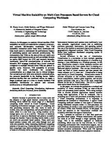
2.1. Stream Programming Figure 2. Stream Processor Block Diagram Media applications contain abundant parallelism and are compute intensive. Rixner studied application characteristics of four media applications: a stereo depth extractor, a video encoder/decoder, a polygon renderer, and a matrix QR decomposition [16]. On these applications, he measured ratios of arithmetic operations to inherent memory references of 57.9 to 473.3 and showed that they contain a large amount of data-level parallelism. These applications are naturally cast as stream programs. A stream program organizes data as streams and computation as a sequence of kernels. A stream is a finite sequence of related elements. Each stream element is a record, such as a 21-word triangle, or single-word RGBA pixels. A kernel reads from a set of input streams, performs the same computation on all elements of a stream, and writes a set of output streams. FFT as an example stream program is shown in Figure 1. In this diagram, arrows represent streams and circles represent kernels, in this case one stage of a FFT. Stream programs expose the locality and parallelism in the algorithm to the compiler and hardware. Two key types of locality are exposed: kernel locality and producerconsumer locality. Kernel locality refers to intermediate
data values that are live for only a short time during kernel execution, such as temporaries during an FFT butterfly computation. Producer-consumer locality refers to streams produced by one kernel and consumed by subsequent kernels. Finally, parallelism is exposed because a kernel typically executes the same kernel program on all elements of an input stream. By casting media applications as stream programs, hardware is able to take advantage of the abundant parallelism, computational intensity, and locality in media applications.
2.2. Stream Architecture An example stream architecture with eight arithmetic clusters is shown graphically in Figure 2. A stream processor runs as a co-processor with a host executing scalar code. Instructions sent to the stream processor from the host are sequenced through a stream controller. The stream register file (SRF) is a large on-chip storage for streams. The microcontroller and ALU clusters execute kernels from a stream program. As shown in Figure 3, each cluster consists
SP
Intracluster Switch
COMM
To/From Other Clusters
To/From SRF
Figure 3. Arithmetic Cluster Block Diagram
of ALUs fed by 2 local register files (LRFs) each, external ports for accessing the SRF, and an intracluster switch that connects the outputs of the ALUs and external ports to the inputs of the LRFs. In addition, there is a scratchpad (SP) unit, used for small indexed addressing operations within a cluster, and an intercluster communication (COMM) unit, used to exchange data between clusters. Imagine is a stream processor recently designed at Stanford University that contains 6 floating-point ALUs per cluster (3 adders, 2 multipliers, and 1 divide-square-root unit) and eight clusters [8], and was fabricated in a CMOS technology with 0.18 micron metal spacing rules and 0.15 micron drawn gate length. Stream processors directly execute stream programs. Streams are loaded and stored from off-chip memory into the SRF. SIMD execution of kernels occurs in the arithmetic clusters. For each iteration of a loop in a kernel, C clusters will read C elements in parallel from an input stream residing in the SRF, perform the exact same series of computations as specified by the kernel inner loop, and write C output elements in parallel back to an output stream in the SRF. Kernels repeat this for several loop iterations until all elements of the input stream have been read and operated on. Data-dependent conditionals in kernels are handled with conditional streams which, like predication, keep control flow in the kernel simple [7]. However, conditional streams eliminate the extra computation required by predication by converting data-dependent control flow decisions into data-routing decisions. Stream processors exploit parallelism and locality at both the kernel level and application level. During kernel execution, data-level parallelism is exploited with C clusters concurrently operating on C elements and instructionlevel parallelism is exploited by VLIW execution within the clusters. At the application level, stream loads and stores can be overlapped with kernel execution, providing more concurrency. Kernel locality is exploited by stream processors because all temporary values produced and consumed during a kernel are stored in the cluster LRFs without accessing the SRF. At the application level, producerconsumer locality is exploited when streams are passed between subsequent kernels through the SRF, without going back to external memory. The data in media applications that exhibits kernel lo-
cality and producer-consumer locality also has high data bandwidth requirements when compared to available offchip memory bandwidth. Stream processors are able to support these large bandwidth requirements because their register files provide a three-tiered data bandwidth hierarchy. The first tier is the external memory system, optimized to take advantage of the predictable memory access patterns found in streams [17]. The available bandwidth in this stage of the hierarchy is limited by pin bandwidth and external DRAM bandwidth. Typically, during a stream program, external memory is only referenced for global data accesses such as input/output data. Programs are strip-mined so that the processor reads only one batch of the input dataset at a time. The second tier of the bandwidth hierarchy is the SRF, which is used to transfer streams between kernels in a stream program. Its bandwidth is limited by the available bandwidth of on-chip SRAMs. The third tier of the bandwidth hierarchy is the cluster LRFs and the intracluster switch between the LRFs which forwards intermediate data in a kernel between the ALUs in each cluster during kernel execution. The available bandwidth in this tier of the hierarchy is limited by the number of ALUs one can fit on a chip and the size of the intracluster switch between the ALUs. The peak bandwidth rates of the three tiers of the data bandwidth hierarchy are matched to the bandwidth demands in typical media applications. For example, the Imagine processor contains 40 fully-pipelined ALUs and provides 2.3 GB/s of external memory bandwidth, 19.2 GB/s of SRF bandwidth, and 326.4 GB/s of LRF bandwidth. Therefore, Imagine supports a ratio of ALU operations to memory words referenced of 28. However, as mentioned above, some media applications have over 400 inherent ALU operations per memory reference. As VLSI capacity continues to scale at 70% annually and as memory bandwidth continues to increase at 25% annually, this suggests that stream processors with thousands of ALUs could provide significant speedups on media applications without becoming memory bandwidth limited. The remainder of this paper will explore the feasibility and performance of such processors.
2.3. Related Work Other researchers have investigated programmable architectures for media processing that scale to many ALUs per chip. Vector microprocessors [10, 22] directly exploit data parallelism by executing vector instructions such as vector adds or multiplies out of a vector register file. This differs from stream processors, which execute VLIW instructions from a kernel in a SIMD fashion out of a SRF and contain LRFs to store intermediate results. Several authors have analyzed the VLSI costs of components of vector microprocessors as the number of functional units per
vector lane is increased [2, 10, 18]. Kozyrakis also analyzed the natural vector lengths in media benchmarks and the performance of vector microprocessors as the number of FUs per vector lane are increased [11]. However, to our knowledge, no previously published studies explore VLSI costs or performance as vector microprocessors are scaled to greater than 8 or 16 vector lanes. Other related work includes approaches where stream programs are mapped to on-chip processor arrays [3, 12, 21] and investigations into the impact of technology scaling on general-purpose microprocessors [1].
3. VLSI Cost Models Not only do stream processors naturally exploit the parallelism and locality in media applications, but they are also area- and energy-efficient, primarily due to their register file structure. Stream processors partition their register file along three dimensions. The first partition is in the SIMD dimension, supporting multiple arithmetic clusters. The next partition is in the instruction-level dimension with one two-ported LRF per ALU input within in the arithmetic clusters. Finally, the SRF is separated from the LRFs in order to allow for staging of streams between memory and kernels. Each of these partitionings provides a benefit in area and energy efficiency with a small performance degradation. In total, when compared to a 48-ALU processor with a single unified register file, a C = 8 N = 6 stream processor takes 195 times less area, 430 times less energy, and has only a 8% performance degradation [18]. This improved VLSI efficiency enables stream processors to scale to thousands of ALUs per processor. In this section, we present analytical models for the area, delay, and energy of a stream processor as a function of the number of clusters C and ALUs per cluster N . The area, delay, and energy of the basic building blocks of a stream processor and other parameters that will be used throughout the paper are presented in Table 1. The first section of parameters includes measurements from a prototype Imagine stream processor [8]. Key building blocks include four types of on-chip memory (SRAMs, LRFs, SPs, and streambuffers), ALUs, and wires. Listed values are process independent. Energy values are normalized to Ew , the wire propagation energy per wire track (0.093 fJ in 0.18 micron technology1 ). Measured delays for on-chip wire propagation and key gates which will be used to construct large switches are presented in fan-out-of-4 inverter delays (FO4s), a process-independent measure of device speed. As technology scales, wire propagation velocity v0 stays relatively constant with optimal repeatering [5]. A clock cycle of 45 FO4s, measured from the Imagine stream proces1 Calculated from an assumed wire capacitance of 0.26 fF per micron including repeater capacitance [5] with a 25% 1-to-0 transition probability.
Table 1. Summary of Parameters Param ASRAM
Value 16.1
ASB wALU wLRF wSP h
2161.8 876.9 437.0 708.9 1400
v0
1400
tcyc tmux Ew
45 2 1
EALU
2.0 × 10⁶
ESRAM
8.7
ESB
1936
ELRF
8.9 × 10⁵
ESP T b GSRF GSB
1.6 × 10⁶ 55 32 0.5 0.2
GCOM M GSP I0
0.2 0.2 196
IN
40
LC LO
6 6
LN rm
0.2 20
ruc
2048
C N
— —
Description Area of 1 bit of SRAM used for SRF or Microcontroller (grids) Area per SB width (grids) Datapath width of an ALU (tracks) Datapath width of 2 LRFs (tracks) Scratchpad datapath width (tracks) Datapath height for all cluster components (tracks) Wire propagation velocity in tracks per FO4 inverter delays [5] FO4s per clock Delay of 2:1 mux in FO4s Normalized wire propagation energy per wire track Energy of ALU operation (normalized to Ew ) SRAM access energy per bit (normalized to Ew ) Energy of 1 bit of SB access (normalized to Ew ) LRF access energy (normalized to Ew ) SP access energy (normalizd to Ew ) Memory latency (cycles) Data width of the architecture Width of SRF bank per N (words) Average number of SB accesses per ALU operation in typical kernels COMM units required per N SP units required per N Initial width of VLIW instructions (bits) Additional width of VLIW instructions per NF U Initial number of cluster SBs Required number of non-cluster SBs Additional SBs required per N SRF capacity needed per ALU for each cycle of memory latency (words) Number of VLIW instructions required in microcode storage Arithmetic clusters Number of ALUs per cluster
Micro-Controller
Kernel Blocksad Convolve Update FFT DCT
ALU Ops 59 133 61 145 150
SRF Accesses 28 (0.47) 14 (0.11) 4 (0.07) 64 (0.44) 16 (0.11)
Intercluster Comms 10 (0.17) 5 (0.04) 16 (0.26) 40 (0.28) 7 (0.05)
SP Accesses 4 (0.07) 2 (0.02) 32 (0.52) 72 (0.50) 32 (0.21)
sor, was used. Typical microprocessors designed with custom methodologies have clock cycles closer to 20 FO4s [1]. Adapting the cost analysis to results for custom processors will be addressed in Section 4. The second section of values were empirically determined from the inner loop characteristics of a variety of key media processing kernels. These characteristics are shown in Table 2 with the number of accesses per ALU operation shown in parentheses. Based on these inner loop characteristics, reasonable values for GSRF , GSB , GSP , and GCOM M were used to make sure that application performance was not affected.
3.1. Stream Processor Cost Models
The total area and energy of a stream processor is subdivided into the SRF, the microcontroller, the C SIMD arithmetic clusters, and the intercluster switch. Other components such as the stream controller and memory system are not scaled with the number of ALUs and contribute a small constant factor to total area, so are not considered in this study. Analytical cost models for the SRF, microcontroller, clusters, and switches are presented in Table 3. The first section contains dependent variables used for clarity, followed by formulae for area, delay, and energy. These models have been adapted from formulae presented by Rixner et al. on the Stream/SIMD/DRF register organization [18]. However, Rixner et al. only considered the register files and the switches between register files and fixed C at 8 in their analysis. In this paper, we extend the models to include the microcontroller, intercluster switches, and scratchpad units. A grid floorplan of arithmetic clusters shown in Figure 4 is assumed. The SRF is partitioned into C banks, where each bank corresponds to an element from a stream that a cluster will read during SRF reads and writes. The only communication between the clusters or SRF banks is in the memory system ports to the SRF (not shown) and the intercluster switch, with buses and cross-point switches represented as lines and dots in Figure 4.
SRF
Cluster
SRF
Cluster
SRF
Cluster
SRF
Cluster
SRF
Cluster
SRF
Cluster
C1/2NCOMMb
Table 2. Kernel Inner Loop Characteristics
C1/2 NCOMM b
Figure 4. Chip Floorplan 3.1.1
Stream Register File
The area of the SRF, ASRF , contains two components: the stream storage and the SBs. The SRF is used to stage streams being passed between kernels. A SB automatically prefetches sequential data for its associated stream out of the stream storage. All SBs share a single port into the stream storage, allowing that single port to act as many logical ports. The stream storage is a large single-ported onchip SRAM, organized as rm T N blocks of C banks, for a total capacity of rm T N C words. This capacity is necessary to cover external memory latency. In a fixed technology, since the area and access energy of the stream storage grow linearly with the capacity, both the area and energy grow linearly with the number of ALUs in a stream processor. Each SB contains storage for two blocks of the SRF to act as a double-buffer for covering the latency of block reads and writes from the stream storage. Each SRF bank has a block width of GSRF N b, requiring 2GSRF N b bits of storage per SB. A total of NSB streambuffers are required for a given stream processor configuration. As shown in Table 3, three factors determine the total number of SBs. LO SBs are required for memory, host, and microcontroller transfers. LC cluster SBs are required to provide an ample number of input and output streams for typical kernels. Finally, as N increases, more bandwidth is often required between some of the SBs and the ALUs. This is accounted for with a third term, LN N . Input or output streams with multi-word records that require more bandwidth must be split into multiple streams and utilize these additional SBs to keep from becoming a performance bottleneck2 . Asymptotically, the 2 Splitting multi-word-record streams into multiple streams was done by hand to optimize performance for the experiments in Section 5.
Table 3. Summary of Stream Processor VLSI Costs Element COMMs per cluster SPs per cluster FUs per cluster Cluster SBs Total SBs External Cluster Ports Total Area SRF Bank Area Microcontroller Area Cluster Area Intracluster Switch Area Intercluster Switch Area Intracluster Wire Delay Intercluster Wire Delay Total Energy SRF Bank Energy Microcontroller Energy Cluster Energy Intracluster Comm Energy Intercluster Comm Energy
Equation NCOM M = GCOM M N NSP = GSP N NF U = N + NSP + NCOM M NCLSB = LC + LN N NSB = LO + NCLSB Pe = NCLSB AT OT = CASRF + AU C + CACLST + ACOM M ASRF = rm T N ASRAM b + (2GSRF N )NSB ASB √b AU C = ruc (I0 + IN NF U )ASRAM + (IN NF U ) ASRF + ACLST + ACOM M ACLST = NF U√wLRF h +√ N wALU h + NSP wSP h + ASW ASW = N ( N b)(2 NF U b + h + 2wALU + 2wLRF )+ F U F U √ √ NF U (3 NF U b + h√ + wALU + wLRF √ )Pe b √ ACOM M = CNCOM M b C(NCOM M b C + 2 ACLST + ASRF ) √ √ √ √ √ tintra = NF U (h + 2 NF U b + wALU + wLRF + NF U b)/v0 + tmux (log2 NF U + √ NF U ) √ √ tinter = tintra + 2 CACLST + CASRF + ACOM M /v0 + tmux (log2 CNCOM M + C) ET OT = CESRF + EU C + CECLST + GCOM M N CbEinter ESRF = rm T N bESRAM GSB /GSRF + (GSB N b)(E √SB√+ Eintra /2) EU C = ruc (I0 + IN NF U )ESRAM + (IN NF U )Ew ( C CASRF + CACLST + ACOM M ) ECLST = NF √ ESP + NF U bEintra U ELRF + N E √ALU + NSP √ √ Eintra = Ew ( √NF U (h + 2 NF U b) + 2 NF U (wALU √ + wLRF + NF U b)) √ Einter = Ew (2 C)( ACLST + ASRF + NCOM M b C)
area of the SBs grows with N 2 , but for N < 64, the linear term accounts for the majority of the area. The energy dissipated in the SBs is related to the number of SB accesses per ALU operations, GSB . Half of the accesses are assumed to be reads and require a traversal of the intracluster switch. 3.1.2
Microcontroller
The microcontroller, listed next in Table 3, provides storage for the kernels’ VLIW instructions, and sequences and issues these instructions during kernel execution. The microcode storage is a large single-ported memory. With a small amount of speedup on this single port, kernels can be loaded before they are used, and separate write and read ports are not needed. The microcontroller area is comprised of the microcode storage area and area for control wire distribution between the microcontroller and the clusters. The microcode storage requires ruc VLIW instructions for kernel storage in typical applications. Although as is shown in Section 5, increasing N results in higher inner-loop performance, the number of instructions in a kernel stays relatively constant with N since more loop unrolling is often used with higher N to provide more ILP and because loop prologues and epilogues in kernels are critical-path limited, not arithmetic-bandwidth limited. The width of each VLIW
instruction is given by I0 + IN NF U bits. I0 bits are required for microcontroller instruction sequencing, conditional stream instructions, immediate data, and for interfacing with the SRF. IN bits per ALU per cluster are required to encode ALU operations, to control LRF read and writes, and to control the intracluster switch. Area and energy for distributing the instructions from the microcode storage to the grid of clusters is accounted for in the second term in both formulae in Table 3. In addition, repeaters and pipeline registers are required within the cluster grid for more instruction distribution, but this area is accounted for in the area measured for the components in Table 1. 3.1.3
Arithmetic clusters
Each cluster is comprised of area devoted to the LRFs, ALUs, a scratchpad, and the intracluster switch. This switch is a full crossbar that connects the outputs of the FUs and the streambuffers to the inputs of the LRFs and the streambuffers. In this paper, the ALUs are assumed to be arranged in a square grid as shown in Figure 5, where each row contains a bus for each ALU output in that row and each column contains a bus for each LRF input in that column. The row-column intersections contain program-controlled cross-point switches that connect rows to columns. This
h NFU1/2 b ALU
ALU
w ALU
RF RF
RF RF
wLRF
4. VLSI Cost Evaluation
Peb Peb
2NFU1/2 b
Figure 5. Intracluster Switch grid structure minimizes the area and wire delay of the intracluster switch when the number of ALUs per cluster is large3 . The area devoted to the intracluster switch includes wire tracks for the wires and repeaters in the rows and columns of the grids and the cross-points between the rows and columns, as shown in Figure 5. Additional area for the external ports from the cluster streambuffers is included as well. The intracluster wire delay is also presented in Table 3. Its first term models the worst-case wire propagation delay incurred in the intracluster switch (width + height of delay through the cross a cluster)/v0 and a term for the logic√ points. The logic delay includes a NF U :1 mux for each row-column to select which ALU to read from on that row, followed by an additional 2:1 mux delay at each additional row in the column to choose between the current row or the adjacent rows. As N increases, the VLSI costs of the 3/2 arithmetic clusters are dominated by the NF U term in the intracluster switch area. 3.1.4
in each row and reads √ from in each column, so there is a bus width of NCOM M b C between each arithmetic cluster. As shown in ECOM M , on average, GCOM M N C intercluster communications will occur for every N C ALU operations, where each intercluster communication switches the capacitance for a bus in its row and in its destination’s column.
Intercluster Switch
The final component of the stream processor area is the intercluster switch, shown in Figure 4. Each cluster has NCOM M buses it broadcasts to in the rows and NCOM M buses it reads from in the columns. Since each cluster can only access stream elements from its SRF bank, the intercluster switch allows kernels that aren’t completely data parallel to communicate data with each-other without going back to memory. It is also used by conditional streams to route data to and from the SRF [7]. A two-dimensional grid structure similar to the intracluster switch is also assumed for the floorplan of the arithmetic clusters. This layout minimizes the area, delay, and energy overhead of the intercluster switch when the number of arithmetic clusters becomes large. Each cluster has NCOM M buses it writes to 3 For smaller numbers of ALUs per cluster, a linear floorplan has comparable area and delay, but for simplicity, only grid floorplans are considered in this study.
In this section, the area, delay, and energy costs of increasing the number of ALUs in a stream processor will be evaluated using the models presented above. The two scaling methods that will be explored are intracluster scaling, increasing the number of ALUs per arithmetic cluster, and intercluster scaling, increasing the total number of arithmetic clusters.
4.1. Intracluster Scaling As N increases, the size and bandwidth of the SRF, clusters, micro-controller, and intercluster switch must all increase according to the formulae presented in section 3. Figure 6 shows the area per ALU for intracluster scaling with C fixed at 8. Average energy dissipated per ALU operation is shown in Figure 7. Both charts are normalized to the values for N = 5, the most area- and energy-efficient configuration. For small N , the overhead from the I0 bits of microcode storage and the COMM and SP units contributes to larger area per ALU. The area per ALU then stays within 16% of the minimum up to 16 ALUs per cluster, at which point the intracluster and intercluster switch start to reduce the area efficiency. The energy efficiency follows a similar trend, although by 16 ALUs per cluster the energy per ALU op has grown to 1.23x of the minimum, due to the intracluster switch and microcontroller instruction distribution to the large arithmetic clusters. The delay of intracluster and intercluster communication is shown in Figure 8. As N increases, intercluster wire delay grows considerably. This delay is dominated by the wire delay between the large clusters. The intracluster delay grows at a lower rate, and includes significant components of both logic and wire delay4 . As measured from the Imagine stream processor, a clock cycle of 45 FO4 delays is assumed, so it is visible from the graph when additional additional cycles of latencies must be added to instructions as N is increased. Note that since wire traversal can be pipelined, operation latency is affected by intracluster scaling, but clock rate is held constant. 4 As N increases, the VLIW compiler could exploit locality in the placement of operations onto the ALUs so that most communications would take place in a single clock cycle and only rarely will data have to be communicated all the way across the cluster. However, this compiler optimization was not available at the time of this study, so was not considered in the delay analysis.
2.0
Area per ALU (normalized to 8 clusters)
Area per ALU (normalized to 5 ALUs per cluster)
2.0
SRF
Clusters
1.0
Microcontroller
Intercluster Switch
0.0
0
16
32
48
64
80
96
112
1.0
SRF Clusters
128
8
16
ALUs per cluster
Energy dissipated per ALU operation (normalized to 8 clusters)
Energy dissipated per ALU operation (normalized to 5 ALUs per cluster)
2.0
SRF Clusters 1.0
Microcontroller Intercluster Switch
0.0
32
48
64
80
96
112
2.0
SRF
1.0
Clusters
0.0 Microcontroller
128
8
16
ALUs per cluster
32
64
Intercluster Switch 128
Figure 10. Energy of Intercluster Scaling
270.0
270.0 225.0
Intercluster Delay
Delay (FO4s)
180.0 135.0
Intracluster Delay
90.0
180.0 135.0
45.0
0.0
0.0
16
32
48
64
80
96
112
128
ALU's per cluster
Figure 8. Delay of Intracluster Scaling
4.2. Intercluster Scaling Compared to intracluster scaling, intercluster scaling incurs more modest VLSI costs. Figure 9 shows the area per ALU as C is increased from 8 to 256, assuming a constant cluster size of N = 5. The area per ALU is normalized to the C = 8 N = 5 processor for comparison to stream processors feasible in today’s technology. The C = 32 processor actually has 3% improved area per ALU over the C = 8 processor as the cost of the micro-code storage is amortized
Intercluster Delay
90.0
45.0
0
256
Number of Clusters
Figure 7. Energy of Intracluster Scaling
225.0
Delay (FO4s)
64
Figure 9. Area of Intercluster Scaling
3.0
16
32
Number of Clusters
Figure 6. Area of Intracluster Scaling
0
Intercluster Switch 128 256
Microcontroller 0.0
Intracluster Delay
8
16
32
64
128
256
Number of clusters
Figure 11. Delay of Intercluster Scaling over more clusters. However at C = 128, the area per ALU is 2% worse than for C = 8, mostly due to area in the intercluster switch. As shown in Figure 10, energy overhead grows slightly faster than area. A C = 128 dissipates 7% more energy per ALU operation than for C = 8. Switch delays with intercluster scaling are shown in Figure 11. Intracluster delay stays constant because the size of each cluster does not change. Increased intercluster delay is incurred mostly from wire delay and not logic delay, but can be fully pipelined, leading to increased operation latency.
Area per ALU (normalized to 32 clusters, 5 ALUs per cluster)
Table 4. Kernels and Applications
2.0
N=2 N=16
Kernel/APP Blocksad
Data 16b
Convolve
16b
Update FFT Noise
1.0
N=5
4.3. Combined Scaling
DEPTH
FP FP FP / 32b FP FP / 32b 16b
By combining intercluster and intracluster scaling, configurations with thousands of ALUs are feasible, as shown in Figure 12. The area per ALU is graphed for 2, 5, and 16 ALUs per cluster with the number of clusters shown on the x-axis. These results show that by scaling to N = 5, or one COMM unit per arithmetic cluster, and then employing intercluster scaling provides the most area- and energyefficient configurations over the range of C from 8 to 128. However, it is important to note that for each C, the additional cost of scaling from N = 5 to N = 10 is only 5-11% and 14-21% worse for area and energy per ALU. Although the preceding analysis used technology parameters typical to a less-aggressive standard-cell design methodology, the results would be similar for a full-custom design. Full-custom processors have clock cycles of less than 20 FO4s [1], but also have smaller functional units and register files, leading to higher absolute performance and lower absolute area and energy. However, similar results would be seen for relative area per ALU, energy overhead per ALU operation, and latency in cycles of intracluster and intercluster communications. In order to further explore the tradeoffs between these two scaling techniques, a performance analysis is presented in Section 5.
CONV
16b
QRD FFT1K FFT4K
FP FP FP
0.0
0
256
512
768
1024
Total ALUs
Figure 12. Area of Combined Scaling
5. Performance Evaluation Performance was evaluated with six media processing kernels and applications, summarized in Table 4. Kernels and applications were written in KernelC and StreamC. StreamC specifies how streams are passed between kernels. KernelC contains the mathematical operations for the kernel codes. Each kernel and application was then recompiled for different architectures using the compilation and programming tools developed for the Imagine stream processor. Kernel inner-loop performance was measured from static analysis of compiled kernels. Applications were
Irast RENDER
Description Sum-of-absolute differences kernel for image processing Convolution filter for image processing Matrix block update for QRD Radix-4 fast Fourier transform Perlin noise function used in procedural marble shader Triangle rasterizer Polygon rendering of a bowling pin with a procedural marble shader. Stereo Depth Extraction on a 512x384 pixel image [6] Convolution filter on 512x384 pixel image 256x256 Matrix Decomposition 1024-point complex FFT 4096-point complex FFT
simulated on a C++ cycle-accurate simulator, holding the dataset size constant across all stream processor sizes. Clock rates and external bandwidths typical to 2007 technology were assumed. The targeted process is a 45 nanometer technology, expected to be available around 2007 [20]. In this technology, a 45 FO4 inverter delay clock period would have a 1GHz processor clock rate. In addition, a memory system able to provide 16 GB/s of external memory bandwidth using eight Rambus channels [15] and a 1GHz host processor issuing stream instructions across a 2GB/s channel were simulated.
5.1. Kernel Performance Kernel inner-loop performance is an important metric for predicting application performance. When running typical media processing applications like DEPTH on the Imagine stream processor, over 80% of execution time is spent in kernel inner loops. In order to study the effect of intercluster and intracluster scaling on kernel inner-loop performance, a suite of kernels was compiled for various stream processor sizes. Functional unit latencies were taken from latencies in the Imagine stream processor and the latencies of communications were taken from the results presented in Section 4. In the Imagine design, half of a 45 FO4 cycle was allocated for intracluster communication delay. Therefore, in the N = 14 configurations, where more than a half-cycle is required for intracluster communication, an additional pipeline stage was added to ALU operations and stream-
Speedup
3
2
Table 5. Kernel performance per unit area Clusters N 8 16 32 64 128 2 0.138 0.135 0.136 0.132 0.133 5 0.133 0.134 0.135 0.132 0.126 10 0.109 0.111 0.104 0.101 0.095 14 0.065 0.080 0.073 0.072 0.067
Blocksad Convolve Update Fft Noise Irast Harmonic Mean
1
0 2
5
10
14
ALUs per Cluster (N)
5.2
Speed-up
Figure 13. Intracluster Kernel Speedup 18 16 14 12 10 8 6 4 2 0
Blocksad Convolve Update Fft Noise Irast Harmonic Mean
8
16
32
64
128
Number of Clusters (C)
Performance Efficiency
The harmonic mean of kernel inner loop performance per unit area on the six kernels is shown in Table 5. A processor with an area of exactly N ALUs performing N operations per cycle (N GOPS at 1 GHz) would have GOPS per area of exactly 1.0 in this table. Table 5 shows that on average across the kernels, configurations with N > 5 have lower performance per unit area due to the intracluster switch area and poorer kernel inner-loop performance. In contrast, performance per area is relatively unaffected by intercluster scaling. Although the C = 8 N = 2 configuration is the most efficient, with performance per area of an ALU of 0.138, the 640-ALU C = 128 N = 5 processor is only 9% worse on performance per area while providing a raw speedup of 33x over the C = 8 N = 2 processor.
Figure 14. Intercluster Kernel Speedup
5.3. Application Performance buffer reads to cover this latency. Similarly, the COMM unit operation latency and instruction issue pipeline depth was determined by the intercluster communication delay. Kernel inner-loop performance speedups over a C = 8 N = 5 processor with intracluster scaling are shown in Figure 13. Most kernels have near-linear speedups to N = 10, because they contain instruction-level parallelism (ILP) and abundant data-level parallelism that can be converted to ILP with software pipelining and loop unrolling. Beyond 10 ALUs per cluster, most kernels begin to have smaller speedups due to limited ILP and increased operation latencies incurred when traversing the larger intracluster switch. Kernel speedups with intercluster scaling are shown in Figure 14. As C increases, some kernels such as Noise, are perfectly data-parallel and contain perfect speedup. Even kernels such as Irast, which rely heavily on conditional stream and intercluster switch bandwidth, are able to hide intercluster switch latency by taking advantage of abundant data-level parallelism. Based on kernel inner-loop performance, intercluster scaling is able to achieve near-linear speedups when scaling to 128 clusters. Intracluster scaling is very effective to 5 ALUs per cluster, and begins to trail off around 10 ALUs to 14 ALUs per cluster, depending on the specific kernel and the number of clusters.
While kernel inner-loop performance suggests achievable speedups if dataset size scaled with machine size, we also evaluated applications with fixed dataset sizes. The speedups of various configurations over a C = 8 N = 5 processor are shown in Figure 15. Sustained performance in GOPS for the C = 8 N = 5 and C = 128 N = 10 processors are also annotated for each application. All applications except FFT1K and FFT4K assume data is initially in external memory. Since FFTs are typically part of a larger application, their performance was measured with input data already in the SRF, and without simulating the bitreversed stores on the output data. The C = 128 N = 10 processor has the highest performance with speedups over the C = 8 N = 5 configuration of 20.5x (311 GOPS) on RENDER and 11.6x (328 GOPS) on DEPTH, and a harmonic mean of 10.4x across the six applications. Intracluster scaling of application performance is similar to kernel performance, mostly affected by the limited ILP in kernels and increased functional unit latencies. This leads to little application-level speedup or even slowdowns in some cases when increasing N from 10 to 14. With intercluster scaling, speedups vary considerably depending on the application. RENDER, for example, is very data-parallel and contains stream lengths limited only by the total number
Speedup over C=8 N=5
2
24.0 20.0
ALUs per Cluster (N) 5 10
311 GOPS
326 GOPS
469 GOPS
138 GOPS
103 GOPS
14 211 GOPS
200 GOPS
16.0 12.0 10.6 GOPS
8.0 4.0 0.0
15.4 GOPS
28.0 GOPS
8 16 32 64 128 8 16 32 64 128
RENDER
DEPTH
41.2 GOPS
25.6 GOPS
14.6 GOPS
18.3 GOPS
8 16 32 64 128 8 16 32 64 128 8 16 32 64 128 8 16 32 64 128 8 16 32 64 128
Number of Clusters (C) CONV QRD FFT1K
FFT4K
HARMONIC MEAN
Figure 15. Application Performance of triangles in a scene. Since this number is large compared to C, it scales very well to large numbers of clusters. DEPTH and CONV, which also contain abundant data parallelism and are not as limited by inherent application stream lengths, also scale quite well. In contrast, QRD and FFT1K scale poorly for C > 32. In QRD, the matrix block update kernels scale well and if the datasets grew with C, QRD performance would scale similarly. However, with a fixed-size dataset, the larger machines spend an increasing fraction of their runtime computing the orthogonal bases for the decomposition, a step which scales poorly, therefore limiting speedup. In addition to algorithmic inefficiencies leading to poor speedups, applications also suffer from short stream effects [14] when stream lengths are comparable to the number of clusters, similar to performance effects due to short vector lengths in vector processors [2]. With short streams, the number of inner loop iterations executed per kernel call decreases, causing a larger fraction of execution time to be spent in loop prologues and epilogues rather than in kernel inner loops. Furthermore, since software pipelining is used extensively to optimize kernel inner-loop performance, a software pipelining priming overhead is incurred. Plus, there is a cost associated with filling the microcontroller and cluster pipeline every time a kernel is executed. Finally, as stream lengths decrease relative to C, memory latency and host processor bandwidth begin to affect performance. Performance degradation from short stream effects is apparent when comparing FFT4K to FFT1K. Although
FFT4K has lower performance than FFT1K at C = 8 N = 5 because its large working set requires spilling from the SRF to memory, at C = 128 N = 10, the difference in raw performance between FFT4K and FFT1K is due purely to stream length. On a C = 128 N = 10 processor, FFT4K sustains 211 GFLOPS, while FFT1K, containing shorter streams, only sustains 103 GFLOPS. In summary, intracluster scaling provides near-linear speedup with a slight cost in performance efficiency until around 10 ALUs per cluster on both kernels and applications. Intercluster scaling provides near-linear speedups on kernel inner-loop performance, and slightly sub-linear performance due to short stream effects on a range of applications. When comparing a 1280-ALU to a 40-ALU stream processor, speedups of up to 27.4x and 10.0x on a harmonic mean of kernels and applications are possible with only a 29% degradation in kernel performance per unit area.
6. Conclusion As technology enables more ALUs to fit on a single chip, architectures must efficiently utilize bandwidth in order to achieve large performance gains. This paper presents two scaling techniques for stream processors that enable large performance gains on media processing applications in future VLSI technologies. Intracluster scaling was shown to be effective from a performance and cost standpoint up to 10 ALUs per cluster, although was most area- and energy-
efficient at 5 ALUs per cluster. Intercluster scaling was shown to be effective up to 128 clusters, with only a slight decrease in area and energy efficiency. Using the scaling techniques presented in this paper, by 2007, stream processors with 1280 ALUs will be able to provide a peak performance of over 1 TFLOPs while dissipating less than 10 Watts. This presents several exciting challenges in stream processing. One area of future work is architectural optimizations that will enable even higher area and energy efficiency, such as utilizing non-fully-connected crossbars for the intracluster and intercluster switches. Another area of future work is to compare these two scaling techniques compare to multiple stream processors on a single chip simultaneously executing different kernels of one stream program. As software tools for exploiting these two techniques mature, the performance and cost advantages of these and other scaling techniques can be explored.
7. Acknowledgments The authors thank Abhishek Das and Peter Mattson for their software tool support, without whom this work would not be possible. This research was supported by an Intel Foundation Fellowship, the Defense Advanced Research Projects Agency under ARPA order E254 and monitored by the Army Intelligence Center under contract DABT63-96C0037 and by ARPA order L172 monitored by the Department of the Air Force under contract F29601-00-2-0085.
References
[8]
[9]
[10]
[11]
[12]
[13] [14]
[15] [16] [17]
[1] V. Agarwal, M. Hrishikesh, S. W. Keckler, and D. Burger. Clock rate versus IPC: The end of the road for conventional microarchitectures. In 27th Annual International Symposium on Computer Architecture, pages 248–259, June 2000. [2] K. Asanovic. Vector Microprocessors. PhD thesis, University of California at Berkeley, 1998. [3] E. Caspi, A. Dehon, and J. Wawrzynek. A streaming multithreaded model. In Proceedings of the Third Workshop on Media and Stream Processors, pages 21–28, Austin, TX, Dec 2001. [4] W. J. Dally and J. Poulton. Digital Systems Engineering, pages 12–22. Cambridge University Press, New York, NY, 1998. [5] R. Ho, K. Mai, and M. Horowitz. The future of wires. Proceedings of the IEEE, April 2001. [6] T. Kanade, A. Yoshida, K. Oda, H. Kano, and M. Tanaka. A stereo machine for video-rate dense depth mapping and its new applications. In Proceedings of the 15th Computer Vision and Pattern Recognition Conference, pages 196–202, San Francisco, CA, June 18–20, 1996. [7] U. J. Kapasi, W. J. Dally, S. Rixner, P. R. Mattson, J. D. Owens, and B. Khailany. Efficient conditional operations for data-parallel architectures. In Proceedings of the 33rd
[18]
[19]
[20] [21]
[22]
Annual IEEE/ACM International Symposium on Microarchitecture, pages 159–170, December 2000. B. Khailany, W. J. Dally, S. Rixner, U. J. Kapasi, P. Mattson, J. Namkoong, J. D. Owens, B. Towles, and A. Chang. Imagine: Media processing with streams. IEEE Micro, pages 35–46, Mar/Apr 2001. G. Konstadinidis, K. Normoyle, S. Wong, S. Bhutani, H. Stuimer, T. Johnson, A. Smith, D. Cheung, F. Romano, S. Yu, S.-H. Oh, V. Melamed, S. Narayanan, D. Bunsey, C. Khieu, K. J. Wu, R. Schmitt, A. Dumlao, M. Sutera, J. Chau, and K. J. Lin. Implementation of a third-generation 1.1GHz 64b microprocessor. In 2002 IEEE International Solid-State Circuits Conference Digest of Technical Papers, pages 338–339, February 2002. C. Kozyrakis. Scalable Vector Media-processors for Embedded Systems. PhD thesis, University of California at Berkeley, 2002. C. Kozyrakis and D. Patterson. Vector vs. superscalar and VLIW architectures for embedded multimedia benchmarks. In Proceedings of the 35th Annual IEEE/ACM International Symposium on Microarchitecture, November 2002. K. Mai, T. Paaske, N. Jayasena, R. Ho, W. J. Dally, and M. Horowitz. Smart memories: A modular reconfigurable architecture. In 27th Annual International Symposium on Computer Architecture, pages 161–171, June 2000. Nvidia Corp. Geforce4 TI 4600 Product Overview, 02.02v01 edition. J. D. Owens, S. Rixner, U. J. Kapasi, P. Mattson, B. Serebrin, and W. J. Dally. Media processing applications on the Imagine stream processor. In 2002 International Conference on Computer Design, pages 295–302, September 2002. Rambus. 512/576 Mb 1066 MHz RDRAM Datasheet, DL0117-030 version 0.3, 3.6MB, 11/01 edition. S. Rixner. Stream Processor Architecture. Kluwer Academic Publishers, Boston, MA, 2001. S. Rixner, W. J. Dally, U. J. Kapasi, P. R. Mattson, and J. D. Owens. Memory access scheduling. In 27th Annual International Symposium on Computer Architecture, pages 128– 138, June 2000. S. Rixner, W. J. Dally, B. Khailany, P. Mattson, U. J. Kapasi, and J. D. Owens. Register organization for media processing. In Proceedings of the Sixth International Symposium on High Performance Computer Architecture, pages 375–387. IEEE CS Press, January 2000. D. Sager, G. Hinton, M. Upton, T. Chappell, T. D. Fletcher, S. Samaan, and R. Murray. A 0.18µm CMOS IA32 microprocessor with a 4GHz integer execution unit. In 2001 IEEE International Solid-State Circuits Conference Digest of Technical Papers, pages 324–325, February 2001. Semiconductor Industry Association. The International Technology Roadmap for Semiconductors, 2001 edition. E. Waingold, M. Taylor, D. Srikrishna, V. Sarkar, W. Lee, V. Lee, J. Kim, M. Frank, P. Finch, R. Barua, J. Babb, S. Amarasinghe, and A. Agarwal. Bearing it all to software: RAW machines. IEEE Computer, pages 86–93, September 1997. J. Wawrzynek, K. Asanovic, B. Kingsbury, D. Johnson, J. Beck, and D. Morgan. Spert II: A vector microprocessor system. Computer, pages 79–86, March 1996.