Extending hypertext conceptual models with process-oriented primitives1 Marco Brambilla Dipartimento di Elettronica e Informazione, Politecnico di Milano Via Ponzio 34/5, 20133 Milano, Italy
[email protected]
Abstract. Web conceptual modeling is a young discipline, which is gaining popularity among Web developers and CASE tool vendors. However, most conceptual models for the Web proposed so far are an evolution of hypermedia models, and pay attention mostly to the specification of data structures and navigation primitives. As the Web becomes a vehicle for implementing B2B applications, the need arises of extending Web conceptual modeling from data-centric applications to data- and process-centric applications. This paper presents a pragmatic approach to incorporate classical process modeling primitives within a Web modeling framework and comments on the experience gained applying the resulting methodology to an industrial case.
1 Introduction Conceptual modeling has been widely recognized as one of the key ingredients of modern software engineering, because it permits developers to formalize their knowledge about the application in a high-level, platform-independent, yet formal and rigorous way. Conceptual models, originated in the database field (E-R model), have spread in the object-oriented community (UML), and have been recently proposed also for Web application development [3, 5]. The first generation of conceptual models for the Web [2, 3, 6, 10] essentially considered Web applications as a variant of traditional hypermedia applications, where the content to be published resides in a database and browsing takes place on the Internet. Therefore, the modeling focus of these methods is capturing the structure of content, e.g., as a set of object classes or entities connected by associations or relationships, and the navigation primitives, represented by such concepts as pages, content nodes, and links. However, a second generation of conceptual models is required, because the Web is more and more being used as the implementation platform for B2B applications, whose goal is not only the navigation of content, but also supporting the business processes occurring within an organization and between the organization and its partners. These second generation models should cope with process and workflow modeling, support Web service interaction2, and integrate data-centric and process-centric modeling primitives into a mix suited to the development of advanced B2B Web applications. This paper reports on an experience of extending a first-generation Web modeling language [3, 4] to support the specification, design and implementation of B2B applications. The proposed approach is lightweight and pragmatic and relies on the following assumptions and objectives: • We are interested in extending Web modeling concepts to cope with process and workflow modeling, not to adapt workflow management systems to the Web. This approach is justified in all those (numerous) contexts where Web B2B applications originate from a previous data-centric Web application. The typical case is an intranet application that is extended to support a complex content 1 2
This research is part of the WebSI (Web Service Integration) project, funded by the EC in the Fifth Framework. Web services are emerging as the technical means of implementing inter-organizational workflows over the Web, where human users and software programs collaborate in the fulfillment of a business process.
management lifecycle or is opened to business partners outside the company. In this case it should be possible to reuse the conceptual model of the original application and extend it to support interor intra-organization processes. • We assume that the business processes behind the Web interface can be schematized as sequences of elementary operations, with a simple control logic based on decision points. More sophisticated business logic (e.g., the algorithm for the explosion of a bill of materials) are not modeled, but treated as a black box. This assumption is true in most content management workflows, where the actions are content production, deletion, and update, and the control logic reduces to the scheduling and approval of changes, and also in most inter-organization processes (e.g., supply chain management), where partners exchange pieces of data (e.g., orders or credit notes) and make decisions based on the status or content of such information. • We want to reuse as far as possible the implementation techniques and tools matured for datacentric Web hypertexts, extending such techniques and tools only in those aspects directly connected to the implementation of multi-organizational process, e.g., the cooperation of application users belonging to different organizations via Web services. In the light of the above assumptions, our contribution can be summarized in the following points: • A web development process that adapts a classic software engineering paradigm (the RUP process model [6]) to the case of process-and data-centric Web applications. • A mix of notations and modeling concepts that supports both the requirements analysis and the conceptual design phases. • A set of extension to a specific Web modeling language, WebML, extending the expressive power of the language to cover process modeling. WebML has been chosen for tactical reasons (we know the language and an extensible CASE tool is available for experimentation), but the proposed approach is of general validity and can be restated in the context of other "first-generation" Web modeling languages. • An implementation architecture, whereby the existing code generation techniques and runtime framework for producing data-centric Web applications from WebML specifications are extended to support B2B applications. The paper is organized as follows: Section 2 briefly outlines the development process underlying our proposal and overviews the mix of notations and techniques that will be addressed in the paper; Section 3 introduces a running case used throughout the paper, which is a simplified version of an industrial application we are implementing; Section 4 presents the requirements specification tasks, including user, process, data, and interface specification; Section 5 addresses the conceptual design phase, which is the core of the entire process. For space reasons, after a brief overview of WebML (Section 5.1), we concentrate on the aspects related to the integration of process modeling within "classical" Web modeling, by showing: 1) how to use data modeling to represent process data (Section 5.2.1); 2) how to extend the WebML hypertext modeling language to capture process enactment requirements (Section 5.2.2); 3) how to map process specifications into hypertexts targeted to the various actors involved in the process (Section 5.2.3). Section 6 discusses the implementation of the proposed modeling primitives in the context of a commercial CASE tool. Finally, Section 7 reviews related works and Section 8 draws some conclusions and presents our ongoing and future work.
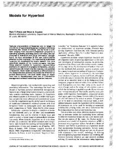
2 Development Process of Web Applications Fig. 1 shows the lifecycle of a data- and process-centric Web application, which consists of requirements specification, conceptual design, the technical tasks of architecture design and implementation, and the steps of testing and evaluation, which may spin-off other iterations over the lifecycle or lead to the deployment of the application and its successive maintenance and evolution. With respect to a purely data-centric Web application, the lifecycle of Fig. 1 augments the conceptual design phase with Process Design, which addresses the high-level schematization of the
processes assisted by the application. Process Design influences the role and content of data and hypertext design, which should take into account process requirements, as we explain in Section 5.2. Business Requirements
REQUIREMENTS SPECIFICATION
CONCEPTUAL DESIGN
PROCESS DESIGN
DATA DESIGN HYPERTEXT DESIGN ARCHITECTURE DESIGN TESTING & EVALUATION
IMPLEMENTATION
MAINTAINANCE & EVOLUTION
Fig. 1. Phases in the development process of data-intensive Web applications
Table 1 overviews the notations and techniques used to support the lifecycle of Fig. 1: for each major phase of the development process (requirements specification, conceptual design, and implementation) we list the notations used for each application perspective (process, data, hypertext). Table 1. Development notations and techniques, charted by process phase and development perspective Focus
DATA
Activity
HYPERTEXT
Data dictionary
Site maps
Entity – Relationship
Hypertext diagrams
Relational schemas
Server side languages (JSP, .NET, …)
ANALYSIS DESIGN IMPLEMENTATION
PROCESS - User groups - Use cases - Workflow diagrams Hypertextual process primitives Server-side components, Web services
For some of these activities, we adopt widely consolidated standards and notations. In particular, data requirements analysis is performed using standard data dictionaries, data design exploits the traditional E-R model, and data implementation is typically obtained through relational technology, although different data implementations can be used. These aspects are quite consolidated and are addressed in this paper only to show how they are affected by the functional requirements about the business processes to support.
3 Running example To concretely illustrate our approach, we will use as a running example an application called Acer Business Portal, developed in collaboration with the European branch of Acer, the international computer manufacturing company. The application aims at providing services to the operators of the Acer's distribution channel, which includes distributors and retailers. Fig. 2 shows the different stages of the supply chain: gray arrows represent the products flow from the producer to the end user and white boxes represent the involved actors. Acer provides products to the channel operators, who are in charge of distributing it. Distributors can be small local entities, country-wide operators, or international distributors. Retailers are the selling points, which allow the final customer to buy products.
Channel Acer
Retail (Reseller)
Distributor
End customer
Fig. 2. The product flow of the Acer distribution channel
The ultimate goal of the Business Portal is to standardize the communication processes of the various channel operators, especially in the area of inventory and sales management, presently managed “offline” using different data exchange formats, communication and information systems, and technological supports. The Business Portal will serve various user groups, including Acer Europe top and middle managers, Acer’s national subsidiaries, distributors, and resellers. In this paper, we consider only a small subset of the real requirements, to exemplify the main aspects of the development methodology. Besides the sales reports exchange, the portal must make distributors and resellers able to electronically submit their refunding requests for stock protection, in case the price of some product falls. The portal should support refunding management, both from the distributor’s side and from the internal Acer personnel’s side.
4 Requirements specification Requirements analysis is the phase in which the business goals of the application are translated into the precise specifications of the application users, of the required data, of the supported processes, and of the application interfaces. We will examine each aspect in turn, paying particular attention to process and interface requirements. 4.1 User and data requirements. The specification of user and data requirements can be performed using traditional means: users are clustered into groups, possibly organized in specialization hierarchies, and data requirements are formalized as a dictionary, which lists the main concepts of the application domain, their essential attributes and relationships. Fig. 3 shows the user taxonomy of the Business Portal application, whereas Table 2 illustrates an excerpt of the data dictionary.
External User
Distributor Guest Reseller
User
Admin
Fig. 3. User taxonomy of the Business Portal application
Internal User
Accountant
Local Mgr
Table 2. Fragment of the data dictionary of the Business Portal application Name Synonyms Description Properties Quantity Old price New price Document No. Request Date Document Date Status Relationships RequestToProduct RequestToDistributor
RefundingRequest None. Is the request of refunding that a distributor submits to Acer Number of sold pieces. Old price of the goods New price of the goods Identifier of the sales document about which the refunding is asked Day in which the refunding request is submitted Date of the sales document about which the refunding is asked Status of the request: not yet evaluated, under consideration, approved It relates the refunding request to the product for which the refunding is asked It relates the refunding request to the user that submitted it
4.2 Functional and process requirements Functional and process requirements formalize the functions required by the users of the application and the structure of the processes where such functions are executed. UML use-case diagrams can be exploited to enumerate the relevant processes and process diagrams to express the flow of activities within a specific use case. For specifying processes, we adopt the terminology and notation defined by the Workflow Management Coalition [13], which is particularly effective in the description of multi-actor workflows. The WFMC workflow model is based on the concepts of Processes, i.e., the description of the supported workflows; Cases, i.e., the process instances; Activities, i.e., the units of works composing a process; Activity instances, i.e., the individual instantiations of an activity within a case; Actors, i.e. the roles intervening in the process, and Constraints, i.e., the logical precedence among activities. Processes can be internally structured using a variety of constructs: sequences of activities, ANDsplits (i.e., points where a single thread of control splits into two or more threads, which can proceed autonomously and independently), AND-joins (points where two or more parallel activities converge), OR-splits (points where a single thread of control makes a decision upon which branch to take among multiple alternative workflow branches), OR-joins (points where two or more alternative branches reconverge to a single common thread of control), iterations for repeating the execution of one or more activities, pre- and post-conditions (entry and exit criteria to/from a particular activity, respectively). OK Ask f or Ref unding Perf ormedby : Distributor
SendNotif ication to Accountant
Verif y Request Inf o
Perf ormedby : Sy stem
Perf ormedby : Accountant
XOR KO
Approv e Request Perf ormedby : Country Mgr Notif y Distributor Perf ormedby : Sy stem
Fig. 4. Workflow diagram of the refunding request process supported by the Business Portal
Fig. 4 exemplifies a WFMC process model specifying the way in which distributors submit requests of refunding for stock protection. A distributor submits a refunding request through the Web portal interface. A notification is sent by the system to the Acer internal accountant in charge of managing the Distributor, who verifies the request. If everything is correct, the request is passed to the Country Manager, who approves it and makes the refunding payable; otherwise the Distributor who applied for refunding is automatically notified by email that his request has been rejected. The functional and process requirements help the specification of the application hypertextual interfaces, as shown in the next section.
4.3 Interface requirements Interface requirements pin down the application interfaces (called site views) needed for accomplishing the requirements of the identified groups and in particular for supporting the identified processes. A site view serves the use cases associated to one or more user groups, offers access or content management functions over selected data elements, and publishes the interfaces for executing the activities of a process. For each site view, a specification sheet is filled, as shown in Table 3. Table 3. Site view specification sheet for the Distributors site view Site View Name Description User Groups Use Cases Site View Map Area Name Products browsing Mailing list subscription Stock protection refunding
Distributor Site View In order to access this site view, Distributors need to login. Then, they can browse the complete Acer products catalog, submit refunding requests, and check their status. Distributor “Login”, “Browse Products”, “Ask for refunding”, “Check refunding status”. Area Description This area allows distributors to browse the products catalog in a topdown fashion, from ProductGroups to ProductBrands and Products This area allows distributors to subscribe to the Acer marketing mailing list This area implements the process of refunding management for the distributor. The user can submit a request through a page containing a form.
Accessed objects Product, ProductBrand, ProductGroup Distributor RefundingRequest
5 Conceptual design Conceptual design is the phase in which requirements are turned into a high-level, platformindependent specification of the application, which can be used to drive the subsequent implementation phase. Our approach to conceptual design relies on the following guidelines: data requirements are used to produce an Entity-Relationship diagram modeling the data stored, manipulated, and exchanged by the application actors, plus the metadata required for the management of the business processes; process diagrams are treated as a higher-level specification and are used to derive a set of hypertext models that "realizes" them. These hypertext models belong to the site views of the user groups involved in the process and must offer them the interface needed for performing the various activities specified in the process diagram. For space limitations, we focus the illustration of the conceptual design phase to the process-related aspects. We start by giving a brief overview of WebML, the notation adopted for modeling the hypertextual interfaces. 5.1 Overview of WebML hypertext modeling primitives WebML [3, 4, 11] is a conceptual language originally conceived for specifying Web applications developed on top of database content described using the E-R model. A WebML schema consists of one or more hypertexts (called site views), expressing the Web interface used to publish or manipulate the data specified in the underlying E-R schema. A site view is a graph of pages to be presented on the Web. Pages enclose content units, representing atomic pieces of information to be published (e.g., indexes listing items from which the user may select a particular object, details of a single object, entry forms, and so on); content units may have a selector, which is a predicate identifying the entity instances to be extracted from the underlying database and displayed by the unit. Pages and units can be connected with links to express a variety of navigation effects.
Besides content publishing, WebML allows specifying operations, like the filling of a shopping cart or the update of content. Basic data update operations are: the creation, modification and deletion of instances of an entity, or the creation and deletion of instances of a relationship. Operations do not display data and are placed outside of pages; user-defined operations can be specified, such as sending e-mail, login and logout, e-payment, and so on. Products Area Home Page ProductGroups
MailingList Subscription Area ProductBrands Page Selected Group
Products Page ProductBrands
Selected Brand
Products
Subscription Page
Insert data
ProductGroup
ProductGroup
ProductBrand [ProdGroup2ProdBrand]
ProductBrand
Product [ProdBrand2Product]
Modify Subscr
Distributor [ID=CurrentUser]
Fig. 5. WebML site view diagram featuring areas, pages, content units, and operations.
Fig. 5 shows a simplified version of the first two areas of the Distributor site view of the Business Portal, whose map have been illustrated in Table 3: the Products area allows guests to browse products, by first selecting in the Home page the product group from an index (ProductGroups) and then by looking at the group details and selecting a specific brand in page ProductBrands. Once a brand is selected, all the products of that brand are shown in page Products. The Mailing List Subscription area allows the user to subscribe to a mailing list through a form. The submitted data (email address and so on) are used to modify the profile of the Distributor. This is obtained by means of a modify operation called Modify Subscr, which updates the instance of entity Distributor currently logged3. 5.2 Extending data and hypertext modeling to capture processes In the specification of a Web application for supporting business processes, the data model, which is normally used to describe the domain objects, is extended with user-related and workflow-related data, and the hypertext model is enriched by a set of primitives that enables the content of pages to be adapted to the status of the workflow. 5.2.1 Extending the data model with process metadata Data modeling is extended with the metadata used to represent the runtime evolution of processes. Fig. 6 shows an E-R model encompassing all the main concepts of the WFMC process model. The schema includes entities representing the elements of a process, and relationships expressing the semantic connections of the process elements. Entity Process is associated with entity ActivityType, to represent the classes of activities that can be executed in a process. Entity Case denotes an instance of a process, whose status can be: initiated, active, or completed. Entity ActivityInstance denotes the occurrence of an activity, whose current status can be: inactive, active and completed. Entities User and Group represent the workflow actors, as individual users organized within groups. A user may belong to different groups, and one of such groups is chosen as his default group, to facilitate access control when the user logs in. Activities are "assigned to" user groups: this means that users of that group can perform the activity. Instead, concrete activity instances are "assigned to" individual users, who actually perform them. Application data is a usual E-R model of the information involved in the current application. In our example, as depicted in the boxed part of Fig. 6, we model the three levels product catalog hierarchy 3 The selector [ID = CurrentUser] specifies that the object to modify is the instance of entity Distributor having ID = CurrentUser, where CurrentUser is a session variable identifying the currently logged user.
(in which each Product belongs to a ProductBrand, and ProductBrands are categorized into ProductGroups), the RefundingRequest and the Distributor profile. RefundingRequest is related to the Distributor who submitted it, and to the Product it refers to. Group
0:N
Workflow Data Model
0:N Assigned To
Name ...
ActivityType
1:N
0:N
0:N
1:N
Default 1:1
1:1
Process Name
PartOf
0:N
0:N
Case
Activity Instance 0:N
1:1 Assigned To
Status StartTimeStamp EndTimeStamp 0:N
1:1 PartOf
1:N Status Name StartTimeStamp EndTimeStamp
RelatedTo
Email SubscribedToML
1:1 Quantity OldPrice RequestToDistributor NewPrice ...
0:N
Name Description 0:N
Product
RefundingRequest Distributor
1:1
ProductBrand
1:1
0:N
Application Data Model
ProductGroup Name PriceList
Type
User Username Password ...
1:1
Name
0:N RequestToProduct
Name Description 1:1 Image TechnicalDetails
Fig. 6. Data model incorporating workflow concepts
The designer can specify an arbitrary number of relationships between the application data and the workflow data, which may be required to connect the activities to the data items they use. This connection can be expressed as a relationship (generically called RelatedTo in Fig. 6), which connects the instances of the application entities with the activity instances where they are used. 5.2.2 Extending the hypertext model with process enactment primitives Besides modeling the metadata for recording the status of processes, it is also necessary to design interfaces capable of producing and consuming such metadata, in order to correctly enact the processes. To ease the specification of hypertexts for executing workflows, a few additional primitives are introduced in WebML for updating process data as a result of activity execution, for accessing the data associated with a specific activity instance, and for expressing the assignment of data objects to an activity instance to be executed in the future. The portion of hypertext devoted to the execution of a process activity must be enclosed between the two workflow-related operations shown in Fig. 7(a): Start Activity and end activity4. These operations delimit a portion of the hypertext devoted to the execution of an activity and have the side effect of updating the workflow data. Specifically, starting an activity implies creating an activity instance, recording the activity instance activation timestamp, connecting the activity instance to the current case (using relationship PartOf), to the current user (using relationship AssignedTo), and to the proper activity type, and setting the status of the activity instance to "active". Symmetrically, ending an activity implies setting the status of the current activity instance to "completed" and recording the completion timestamp. The Start Activity operation can also be tagged as the start of the case, when the activity to start is the first one of the entire process; dually, the End Activity operation can be tagged as the end of the case. At case start, a new case instance is created with status=“running”; when the case ends, its status is set to “terminated”. Fig. 7(b) shows the graphic notation for case start / end.
4
This means that the link(s) entering the portion of hypertext associated with the activity must trigger the Start Activity operation and the link(s) exiting such portion of hypertext must trigger the end activity operation.
Start Activity
End Activity
Start Activity
End Activity
Current User
Requests
ReqID
Assign A
Amount
If
W
ActivityName
ActivityName
(a)
ActivityName
ActivityName
(b)
[true] [false]
RefundingRequest [ActivityType="Approval"] [User=CurrentUser]
RefundingRequest [Activity="Approval"] [User=CurrentUser] [Case=CurrentCase]
(c)
(d)
Amount>1000$
(e)
Fig. 7. Start Activity and End Activity operations (a), eventually denoted with start and end case notations (b); workflow-aware content unit notation(c); graphical notation of the Assign operation (d) and of the conditional operation (e)
For retrieving the data objects related to the instances of a particular activity, workflow-aware content units can be used. These units are like the regular WebML content unit but are tagged with a "W" symbol denoting a simplified syntax for their selector, which shortens the expression of predicates involving both application data and workflow data. For example, Fig. 7(c) shows a workflow-aware index unit that retrieves all the instances of entity RefundingRequest, relevant to the user passed as a parameter to the unit and related to activities of type “Approval”. The assign operation is a WebML operation unit conceived for connecting application object(s) to an activity instance, for which an activity type, a case and possibly a user are specified. Fig. 7(d) shows the graphical representation of the assign operation, which assigns a RefundingRequest to the activity called "Approval", for the current case and for the currently logged user. Thus, the assign unit permits the specification of a "data connection" between activities. The navigation of a hypertext may need to be conditioned by the status of activities, to reflect the constraints imposed by the workflow. Two dedicated operations called if and switch operations allow conditional navigation, performing the necessary status tests and deciding the destination of a navigable link. Fig. 7(e) shows an example of if operation: when the incoming link transporting the Amount parameter is navigated, the condition is tested, and the appropriate link is followed. 5.2.3 Mapping process diagrams to hypertexts supporting process enactment Workflow activities are realized in the hypertext model by suitable configurations of pages and units representing the interfaces for executing them, enclosed between Start / End activity operations. Activity precedence constraints are turned into content publication and navigation constraints among the pages of the activities, ensuring that the data shown by the application and user navigation respect the constraints described by the process specification. To better understand this design phase, we exemplify the hypertext realization of the sequence, the simplest WFMC constraint, and of the AND-split/ AND-join connectors. Sequence. Given two activities A and B, the constraint expressing that activity B must be performed after activity A can be realized as a hypertext specification as illustrated in Fig. 8. Fig. 8(a) shows a first realization based on an explicit link going out of the page implementing the interface of Activity A5: navigating the link terminates activity A, starts activity B and opens the page for executing B; Fig. 8(b) shows an alternative realization based on data coordination: when the link outgoing the page of Activity A is navigated, it assigns some data to activity B; the page of activity B can be accessed at any time, but activity B can be performed only when some data assigned from activity A is available in a workflow-aware content unit, like the index unit shown in Fig. 8(b). If no data has been assigned to activity B, the index remains empty and thus the link for stating activity B cannot be navigated.
5
The example uses empty rectangles to denote the interface of an activity. In reality, an activity interface contains specific pages, units, and operations linked to yield a concrete hypertext for performing the activity.
pages/ units
...
Activity A pages/units
Start Activity
End Activity
Activity B pages/units
...
End Activity
A
pages/ units
...
...
A
a)
Start Activity
B
B
b) pages/ units
Activity A pages/units
Start Activity
...
Assign
... A
pages/ units
...
...
A
Application [Activity="B""] [Case=CurrentCase]
Applic. Index
pages/ units
End Activity
A
Activity B pages/units
Start Activity
pages/ units
End Activity
...
...
W Application [Activity="B"]
B
B
Fig. 8. Hypertext realization of the sequence
AND-split/ AND-join. Fig. 9 shows an hypertext diagram representing AND-split/ AND-join. In this realization, activities A and B can be performed by the same user in any order; when both activities have been terminated, activity C can start. From the initial page the user may either choose activity A or activity B; after termination of activity A (B) a test condition checks if activity B (A) has not been executed yet. If this condition is true, a navigation link leads the user to the starting point of activity B (A), so that also activity B can be executed; instead, if both activities have been completed, the next activity C is started. It is important to notice that in this example parallelism is achieved through serialization to facilitate the user, which is the same for the two activities. However, it is possible to set up hypertextual schemas which grants real parallelism between activities, both for single and for multiple users. Start Activity
Activity A pages/units
End Activity
If [false]
... Page
[true]
A
A
Start Activity
pages/ units
... Activity B pages/units
[true] End Activity
C
If [false]
... B
Start Activity
B
Fig. 9. Hypertext realization of the AND-split AND-join structures
Similarly, pre-conditions, post-conditions, OR-splits and OR-joins can be represented in hypertext diagrams. Pre- and post-conditions are modeled using if and switch operations, leading the user to the right activity depending on the status of the current case. Splits can be modeled in different ways depending on the actor who takes the choice: if a human user chooses the branch to be executed, this will be modeled through links exiting from the pages where the choice is taken; if the system must choose automatically, this will be modeled by means of conditional operations (if and switch operations), automatically executed by the system.
Distributor Site View CreateReq
Connect
Distributor Home page
StartActivity
EndActivity
Assign
Requestpage
A
DataEntry RefundingRequest RequestToDistributor RefundingRequest RequestSubmission [User:=CurrentUser] [Activity="Verify"] [Case=CurrentCase]
… RequestSubmission
EndActivity
SendMail
StartActivity
Notify
Notify
Accountant Site View
AccountantHomepage Requests
Validationpage Details
StartActivity
Confirm Accepted
W
ModifyReq Verify
RefundingRequest [Activity="Verify"] EndActivity
NotifyDistributor
SendMail
StartActivity
NotifyDistributor
RefundingRequest
EndActivity
Assign
Rejected Distributor [RequestToDistributor]
EndActivity
A
Distributor
RefundingRequest RefundingRequest [Activity="Approval"] [Case=CurrentCase]
Verify
Verify
CountryManager Site View Approvalpage
ManagerHomepage Requests
StartActivity
Details
DataEntry
ModifyReq
EndActivity
W
RefundingRequest [Activity="Approval"]
Approval
Request
RefundingRequest
Approval
Fig. 10. Three site views realizing the refunding request process specified in Fig. 4
Fig. 10 shows the complete hypertext schema corresponding to the process specified in Fig. 4, representing the submission of refunding requests. Relevant actors are Distributors, Acer Accountants and Acer Country Managers. For each of them, a site view is designed. From his Home page, the Distributor can follow a link to refunding request submission page. The navigation of the link triggers the Start Activity operation for the RequestSubmission. Since this activity starts a new process case, the Start Activity operation is marked as start case with a small white circle on the left. Once the activity is started, the distributor reaches the Request page, where he can submit the request data through a form(called Data Entry). When the user navigates the outgoing link of the Data Entry unit, an operations chain6 is lauched. A new RefundingRequest object is instantiated in the database by the CreateReq operation (with the proper attributes values) and connected to currently logged user through the RequestToDistributor relationship. The request is then assigned to the next activity in which it is involved (the Verify activity, to be performed by the Accountant). The RefundingRequest is then ended, and the Notify activity, that sends a notification email to Acer
6 An operation chain consists of a set of operations directly connected each other through links. The chain can be activated by a click of the user, that triggers the start of the first operation. Once an operation is terminated, the link to the next one is automatically navigated and the next operation is executed.
Accountant, is automatically performed by the system, since links between operations are always automatically navigated. The Accountant can see in his home page the list of the RefundingRequests to be processed (i.e., assigned to the Verify activity). By choosing one, he starts the Verify activity on it, and is led to the Validation page, in which he can accept or reject the RefundingRequest. The page shows the details of the request and of the Distributor who submitted it. If he accepts the request, by clicking on the submit button in the Confirm form, the RefundingRequest status is modified to accepted, then the request is assigned to the Approval activity, and the Verify activity is ended. If he rejects the request, the Verify activity is ended as well, but then the NotifyDistributor activity is automatically performed. In this example, the choice between the two branches of the split in the process is manually performed by the Accountant, and therefore no decisions must be taken by the system by means of if / switch units. This activity is the last of the process, therefore the End Activity operation is marked with the black circle on the right that denotes the EndCase property. The Country Manager can see in his Home page all the requests that have been verified by an Accountant, and that are now assigned to the Approval activity. He can definitively approve a request, by selecting it from the index in his Home page, and changing its status to approved in the Approval page. This is achieved by means of the Modify Req operation, which updates the Status attribute of the current RefundingRequest. Since the Approval activity is the last of the process, the corresponding End Activity operation is marked as EndCase.
6 Implementation and experience The modeling approach discussed in this paper has been implemented in the context of a commercial CASE tool, called WebRatio [12], which supports the model-driven development of data-intensive Web applications. WebRatio has an extensible architecture, where new modeling primitives can be plugged into the design environment, code generator, and runtime framework, by writing Java or C Sharp components and wrapping them using XML descriptors and XSL style sheets. The conceptual modeling approach proposed in this paper has been implemented by performing several extensions of WebRatio: • The default data schema of WebRatio applications has been augmented to incorporate the workflow-related entities and relationships shown in the upper part of Fig. 6. • The WebML diagram editor has been extended to support the specification of WFMC process diagrams. The code generator has also been extended to translate process diagrams into the skeletons of the site views associated with the actors involved in the process. This translation implements the mapping rules between process and hypertext diagrams exemplified in Fig. 8 and produces empty activity interfaces, plus all the auxiliary operations needed for activity synchronization (Start Activity/ End Activity, start case/ end case). The XSL translator covers a subset of the WFMC primitives including activity sequences, AND/OR splits and joins, and conditional branching. The designer can extend the automatically produced site views by "fillingin" the empty activity pages with the content units and operations needed for performing activityspecific tasks, like content creation, approval, modification, message sending, and so on. • The workflow-related units shown in Fig. 7 have been implemented as a package of custom content units and operations, which add up to the built-in hypertext-modeling primitives of WebML. The code generator has been consequently extended to translate workflow-related units into sequences of native WebML content and operation services, executable in the WebRatio runtime framework. The ideas discussed in the paper is being benchmarked in the development of the Acer Business Portal Web application, which is being implemented as an extension of a previous application, modeled in WebML. The original application was limited to offering information browsing functions to the channel operators and Acer personnel. The new version supports a number of business processes, which are being integrated into the exiting portal by adding new site views for the novel user groups
and new hypertextual interfaces to the site views of existing user groups, devoted to performing the activities of the newly identified business processes. The embedding of process-oriented modeling in the context of a structured Web development methodology eases the management of changes, because designers can analyze the novel requirements and redesign the application at the conceptual level, leveraging the already existing data and hypertext models.
7 Related work WebML [3, 4, 11] is one of a family of proposals for the model-driven development of Web sites, which includes also other approaches, e.g., Araneus [8], Strudel[6], OO-HDM [10], W2000 [2]. Among these, only Araneus has been extended with a workflow conceptual model and a workflow management system. Differently from our proposal, Araneus extensions offer a conceptual business process model and aim at allowing the interaction between the hypertext and an underlying workflow management system. In other words, the Web site is used as an interface to the WFMS. With this philosophy, the data-access and the process-execution layers are at the same level, and are accessed through the hypertext exactly in the same way. This is a good solution for all the cases in which a WFMS is already in place, and only the interface has to be redesigned for the Web context. Many commercial enterprise toolsuite, such as IBM MQSeries Workflow [8] and Oracle Workflow 11i [9] implement complete workflow management systems, based on workflow engines. These tools aim at integrating different enterprise applications, often developed by the same vendor, but application and workflow Web publishing consists in re-building the application for the Web context (e.g., as Java applets) and applying workflow rules for their cooperation. This approach is completely different from our proposal, since we work at extending hypertext modeling with high-level workflow primitives, accompanied to a light-weight workflow implementation, whilst industrial WFMSs provide complete workflow engines as native feature, and extend them through Web technologies. The main drawback of this philosophy is that the hypertext navigation power is not completely exploited in the resulting applications, because they often consists in a re-building of the legacy enterprise software. On the other hand, our proposal does not provide a workflow engine, but a methodology and a highlevel modeling framework for a homogeneous description of a Web application with workflow constraints, helping the designer conceptualize and organize an application involving roles and workflow-style paradigms. Our approach is suitable for lightweight applications, which are very common on the Web, and is based on simple concepts, whose code can be automatically generated.
8 Conclusions and future work In this paper, we have discussed the adaptation of data-centric Web conceptual modeling to processoriented applications, such as B2B Web applications. This adaptation requires complementing the activities and artifacts of Web requirement analysis and conceptual design with notations and techniques for capturing the constraints that stem from the process structure and for embodying such constraints in the hypertextual interfaces of the application. To do so, we have extended an existing Web modeling language (WebML) and its underlying development process, incorporating process modeling and the translation of process models into suitable metadata and hypertext structures. This extension permits a smooth integration of process modeling within Web design methodologies, by standardizing the way in which process diagrams are transformed into the hypertext diagrams that realize the process. The main advantage of our approach consist of the easy definition of process-driven Web applications. With respect to traditional Web applications the new primitives grant an immediate help in activity tracking, process status checking and workflow-related data extraction. The result of the design can be a real workflow application, exploiting all the power of complex hypertexts. This is a
typical requirement of most Web applications, e.g., enterprise content publishing sites, self-registration wizards, e-commerce payments, event and travel booking and purchase, and so on. Our future work will proceed along four directions: more complex process modeling features will be considered, to widen the spectrum of process diagrams to which the proposed approach can be applied; further experiments will be conducted with CASE tools, to better automate the derivation of hypertext from process models; scouting of methods for failure and consistency management in processes execution on traditional WFMS is going on, to prepare the basis for the failure and recovery analysis in the context of Web applications; finally, verification rules for keeping the hypertext model aligned with the process model during evolution and maintenance will be studied and implemented. Orthogonally, we are experimenting novel architectural paradigms for deploying process-centric applications. The current implementation assumes that all the site views are deployed as dynamic page templates and server-side components running in a centralized host, which also contains the database storing the application data and the process metadata. Each party in the process must log into the central host for participating to the process. We have started implementing a different architecture based on data distribution and Web services, where both the application data and the process metadata can reside at the premises of the organizations involved in the B2B application (e.g., at Acer's central site and at the sites of the various channel operators). Synchronization is achieved by Web service calls: a given party A can expose Web services whereby other remote parties can selectively update A's data and the process-related metadata relevant to A's view of the ongoing process. In this way, the central data repository is replaced by several distributed local repositories and process synchronization takes place through asynchronous messaging rather than by updates performed in a central database.
Acknowledgments We are grateful to Stefano Ceri, Piero Fraternali, Ioana Manolescu, Sara Comai and the whole team of the WebSI project for the stimulating discussions and ideas on workflow and hypertext integration. We wish to thank also Emanuele Tosetti of Acer Europe for providing the specifications of the Business Portal application and all the Acer personnel who collaborate to the development.
References 1. Atzeni, P., Mecca, G., Merialdo, P.: Design and Maintenance of Data-Intensive Web Sites. EDBT 1998: 436450. 2. Baresi, L., Garzotto, F., Paolini, P.: From Web Sites to Web Applications: New Issues for Conceptual Modeling. ER Workshops 2000: 89-100. 3. Ceri, S., Fraternali, P., Bongio, A.: Web Modeling Language (WebML): a modeling language for designing Web sites. WWW9/Computer Networks 33(1-6): 137-157 (2000) 4. Ceri, S., Fraternali, P., Bongio, A., Brambilla, M., Comai, S., Matera, M.: Designing Data-Intensive Web Applications, Morgan-Kaufmann, December 2002. 5. Conallen, J.: Building Web Applications with UML. Addison Wesley (Object Technology Series), 2000. 6. Fernandez, M. F., Florescu, D., Kang, J., Levy, A.Y., Suciu, D.: Catching the Boat with Strudel: Experiences with a Web-Site Management System. SIGMOD 1998: 414-425. 7. Jacobson, I., Booch, G., Rumbaugh, J.: The Unified Software Development Process. Addison Wesley, 1999. 8. IBM MQSeries Workflow Homepage: http://www.ibm.com/software/ts/mqseries/workflow/v332/ 9. Oracle Workflow 11i: http://www.oracle.com/appsnet/technology/products/docs/workflow.html 10. Schwabe, D., Rossi, G.: An Object Oriented Approach to Web Applications Design. TAPOS 4(4): (1998). 11. WebML Project Homepage: http://www.webml.org 12. WebRatio Homepage: http://www.webratio.com/ 13. Workflow Management Coalition Homepage: http://www.wfmc.org