sample representative database show promising results. 1. ... fore, we propose a novel fingerprint matching scheme in the .... from the free NIST databases [1].
Fast and Robust Projective Matching for Fingerprints using Geometric Hashing Rintu Boro Sumantra Dutta Roy Department of Electrical Engineering, IIT Bombay, Powai, Mumbai - 400 076, INDIA {rintu, sumantra}@ee.iitb.ac.in
Abstract Fingerprint matching is the most important module in automatic person recognition using fingerprints. We model the nonlinear distortions and noise obtained during the fingerprint capture process as transformations in the projective domain. Matching of the fingerprints involves computing the homography matrix for the projective transformation, mapping of the minutia points by this homography and finally computing the points that match each other within a pre-determined threshold. We perform a fast match using a Geometric Hashing-based algorithm which matches the points in polynomial time. Preliminary experiments with a sample representative database show promising results.
1. Introduction A fingerprint is basically the impression of the pattern of alternate ridges and valleys found on the surface of a finger. These ridges exhibit anomalies such as ridge bifurcations and ridge endings and singular points called core and delta points. These points are collectively called minutia points. Classification and Matching of fingerprints is done on the basis of the correlation of these minutia points in the fingerprint images. Figure 1 shows the two commonly observed minutia. Since the problem of point pattern matching is of
to match minutia points in the point pattern domain. Therefore, we propose a novel fingerprint matching scheme in the projective domain by Geometric Hashing. Our method first models the fingerprint capture process as a case of projective transformation. We propose that different fingerprint images of the same finger are related by a homography. Matching of fingerprints thus involves calculation of this homography matrix, using it to map the test minutiae upon the template minutiae and calculating the number of minutia points that match each other within a threshold. Matching of the projectively transformed minutia points is done using a Geometric Hashing-based method as it reduces the time complexity from exponential to polynomial under the assumption of the underlying transformation. There have been several approaches to fingerprint matching, like image-based [10], graph-based [2] and feature space-based [7], [6]. Our approach is based on the point pattern-based approach. Unlike the other approaches, our approach keeps a small template size and hence is faster and robust. This approach models the entire fingerprint image based on the location of the minutia points alone and therefore has a smaller template size. Further, the use of Geometric Hashing for the matching of the projective domain features ensures faster matching of fingerprints. The organisation of the rest of the paper is as follows. Section 2 explains the projective modeling of fingerprints. We explain the Geometric Hashing algorithm in Section 3 and finally section 5 gives the experimental results.
2. Projective Modeling of Noisy Distorted Prints of the Same Finger
Figure 1. Fingerprint ridge bifurcation and ridge ending. This is Figure 2 in Jain et al. [3], page 802.
exponential time complexity, it is not practically feasible
In general, two prints of the same finger are related by a nonlinear transformation because of non uniform pressure variations and noise. Jain et al. handles this nonlinearity by using an elastic matching process [3]. The process involves representing the minutiae patterns as a string in the polar coordinate system and using a string matching algorithm. We model the relation between two fingerprints by a 2-D projective transformation. A projective transformation is the most general case of linear transformation, which subsumes
Euclidean transformations (rotation, translation), similarity transformation (which accounts for uniform scaling also), and affine transformation (which additionally accounts for shear and non-uniform scaling). Hence, we propose that the fingerprint images of the same finger are related to each other by a homography H as per the equation below. λp0 = Hp
Any four distinct non-collinear coplanar points form a projective basis for the plane they span. Given four such points A, B, C, D, a fifth point M in the plane can be characterized as the intersection of one line of the pencil through D with one line of the pencil through B, as in the figure 3. Hence, M can be parametrized by two cross ratios.
(1)
where λ is a constant, p0 and p are the coordinates of the minutiae in the template and test fingerprint images respectively and H is the corresponding homography to be calculated. This modeling for fingerprints takes into account rotations, translations, scaling (both uniform and nonuniform), shear, and other projective effects that occur during the fingerprint capture process. Instead of using the generic method of calculating the homography for the projection, we use an equivalent and elegant computational method by calculating the fundamental projective invariant, the cross-ratio. The cross ratio has been successfully used for applications like robust point based 2D object recognition [8], [9]. The cross-ratio generates a scalar from four points of any 1-D projective space. Let U and V be two lines in the projective plane, defined by their dual coordinate vectors. Then Wi = λi U + µi V defines the pencil of lines through the intersection of U and V . The cross ratio of four lines of a pencil equals the cross ratio of their points of intersection with an arbitrary fifth line transversal to the pencil (i.e not through the pencil’s centre). Figure 2 shows four lines of a pencil through the point O. If
Figure 3. Locating a fifth point in a plane.
In our case, we take a set of four non-collinear minutia points as the basis for our projective framework and parametrize the other minutia points in terms of the cross ratio of the pencil of lines as illustrated above. Finally, taking a cue from the concept of elastic matching [4], [3], we do a matching of the cross ratio values of the test and the template images using Geometric Hashing. We approximate the correspondence-finding method by the most general linear transformation and the fact that these estimates could be off by noise.
3. Geometric Hashing for Fast Minutiae Alignment
Figure 2. Four lines of a pencil.
Li , i = 1, . . . , 4 be any four lines intersecting in O, and Ai , i = 1, . . . , 4 be any four points respectively on these lines, then the cross-ratio of these points is given by L1 , L2 ; L3 , L4 =
|OA1 A3 ||OA2 A4 | |OA1 A4 ||OA2 A3 |
(2)
where |OAi Aj | denotes the determinant of the 3 × 3 matrix whose columns are the homogeneous coordinate vectors of points O, Ai and Aj .
Minutiae alignment requires matching M points in one image with N points in another. As such, this process has an exponential time complexity, O(M N ). Lamdan et al. [5] propose Geometric Hashing as a fast method for 2-D object recognition, where M object points are to be matched to N image points, restricted to an affine framework. We generalize this idea for minutia matching , according to the specific transformation between two images – Euclidean, Affine, or the most general Projective case. A 2-D transformation requires K basis points (K = 3 for Euclidean and Affine, 4 for Projective). We can select�ordered pairs of K basis points from the first image in M K K × K! ways (this is O(M )). For each such basis, we compute the coordinates of the remaining M − K (O(M )) points. A hash table stores these coordinates, indexed by the basis points. We repeat the process for the second image. Matching rows of coordinates between hash tables of the two images has quadratic time complexity. We can reduce this to linear is we sort each row in the hash tables.
Hence, the problem of matching image features reduces to O(M K+1 N K+1 ) × the row matching time. This has polynomial time complexity, an improvement over the exponential time complexity required for a naive feature match.
4. The Overall Scheme The table in the figure 4 gives a step by step overview of the algorithm used for our fingerprint matching algorithm. ALGORITHM match query 01. Read the query image. 02. Obtain the block directional image. 03. Determine the core point. 04. Crop a 120 × 120 image around the core point. Call it Region of Interest (ROI). 05. Thin the ROI. 06. Obtain the minutia points. 07. Obtain the cross ratio values, Store them in a 2-D hash table. 08. Sort each row of the hash table. 09. Compare each row of the query hash table with the template hash table. 10. Declare match based on pairs meeting the threshold criteria. Figure 4. The Proposed Algorithm: A Summary
5. Experimental Results Our preliminary experiments involve a database containing 56 × 5 fingerprint images of size 256 × 256. Five impressions of each finger are available for each of the 56 different fingers accounting for a total of 280 fingerprints. The images contain a mix of locally scanned fingerprints using c fingerprint scanner manufactured by NITthe Hamster GEN biometric solutions, as well as fingerprints obtained from the free NIST databases [1]. The experiments were carried out in a 500 MHz, Pentium III machine running the Red Hat Linux 7.1 operating system. Each fingerprint image in the database is compared with all the other fingerprints in the database. A matching is labeled as correct if the matched pair are images from the same finger and wrong otherwise. The subsections below explain in brief the various steps of the algorithm shown in figure 4. To reduce the size of the feature space (number of minutia points to match), we look only at ridge bifurcations as minutiae. Moreover, we extract a 120 × 120 region around the core point called the region of interest and only match the minutia extracted from this small region. This heuristic
is motivated by the fact that the probability of occurrence of the central region in a fingerprint is more than the peripheral region due to the radial pressure variation during the fingerprint capture process. Moreover, the larger the fingerprint image, the probability of old minutiae shifting out of the image and new minutiae coming in is more and hence it could affect the probability of a match. We observe that a 120 × 120 image around the core point is small enough for faster execution of the matching algorithm and at the same time has enough minutia points to distinguish fingerprints of different fingers. We have got encouraging results using this heuristic. We have implemented two different methods for extraction of minutia points. The first method extracts the minutia points by looking at the directional image of the fingerprint. Those blocks showing multiple dominant directions are marked as sites for probable minutia points. The algorithm for obtaining the block directional image is taken from [11]. The second method extracts minutia points from the thinned image of the fingerprint. Jain et al. [4] use this algorithm and obtain good results. This algorithm looks directly at bifurcations and endings by examining the neighbourhood regions of ridge pixels. We have obtained better and encouraging results for minutiae extraction from the second algorithm and hence, we use that for our experiments. We explain the minutiae extraction process in detail below.
5.1
Detection of the core point
The algorithm at first detects the core point in the fingerprint image by computing the block directional image. These are steps 2 and 3 in the algorithm in figure 4. We use the singular point detection algorithm of Srinivasan and Murthy [11] for detection of the core point. The fingerprint image is divided into blocks and a block directional image is obtained by computing the direction at each pixel. The direction D(i, j) at a point (i, j) in an image is calculated as the direction d for the sum of differences in Pwhich M −1 gray level values, Sd = m=0 |G(im , jm ) − G(i, j)| for d = 1, . . . , N along the direction d is minimum. G are the gray level values, M is the number of pixels used for computation and N is the number of directions used. Each block is then assigned the dominant direction of the pixels in that block and the block directional image is obtained. We have used the value of M as 8 and N as 8. Figure 5 shows results of this algorithm. Once the block directional image is obtained, all points exhibiting a directional difference of greater than 45◦ are labeled as cores. After the core point has been detected, a 120 × 120 region around the core point is extracted and used for further processing. This procedure is step 4 in the algorithm in figure 4. Figure 6 shows the original image and the extracted region of interest around
Figure 7. Original image and its thinned counterpart. Figure 5. Original fingerprint image and the corresponding block directional image.
the core point. It is important to note that we do not use the
Figure 8. Fingerprint image with the detected minutiae marked.
Figure 6. Original fingerprint image and the extracted region of interest.
detection of the core point for the purpose of aligning the query image with a database image. We detect core points only to find the region around it - as mentioned at the beginning of Section 5, this region stands a better chance of being present in most fingerprint images, which could be rolled prints, or chance prints. As mentioned above, we use a robust algorithm to detect core points - this has worked for images in our database. There were a few cases where a spurious point was detected as the core. However, for the query image, the same point was again detected as the core, resulting in the same region being identified in the query and database images. Scope for future work includes working with a large number of images for which either core points are not detected, or spurious core points are detected - this will identify a breakpoint in our approach.
Seun’s [12] thinning algorithm for our experiments. Figure 7 shows a fingerprint image along-with its thinned image. We assign a ridge pixel a value of 1 and a valley pixel a value of 0. Let (x, y) denote a pixel on a thinned ridge and N0 , N1 , . . . , N7 denote its eight neighbours. After thinning the image, we extract the minutia points from the image (step 6 in figure 4). A pixel (x, y) is a ridge ending P7 P7 if i=0 Ni = 1 and a ridge bifurcation if i=0 Ni > 2. Before applying the minutiae detection algorithm on the thinned image, undesired holes and breaks are removed by applying a smoothing operation. The smoothing operation removes holes by deleting any isolated ridge points surrounded by valley pixels or an isolated valley pixel surrounded by ridge pixels. Moreover, if a break in a ridge is shorter than 10 pixels and no other ridges pass through it, then the break is connected. This operation assures that there are no undesired breaks in the thinned image and the subsequent detection of wrong ridge endings. Figure 8 shows the fingerprint images with the minutia points marked on them in green. For each detected minutiae, the coordinates (x, y) are extracted and then these coordinates are used in the matching phase.
5.3 5.2
Application of the matching algorithm
Thinning and Extraction of Minutia Points
The next step (step 5 in figure 4) in the matching process is thinning of the image. We have used Zhang and
Once the correct set of minutia points is obtained, we apply our novel matching algorithm to detect the correct match for the input fingerprint. This module is as per steps
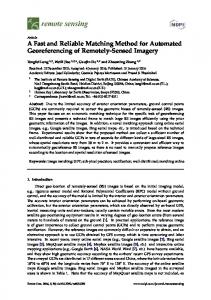
7-10 of the algorithm shown in figure 4. The fingerprint image is modeled as a projectivity in the P2 domain. Taking four non-collinear minutia points at a time as the projective basis, a fifth minutia point is parametrized with the cross-ratio value of the pencil of 4 lines through the basis minutia point closest to this fifth minutia point. Instead of calculating the cross ratio values of the pencil of lines through all the four basis points, this heuristic reduces the time consumed enormously and also parametrizes each minutia point uniquely thus satisfying our criteria for matching. These 4 lines are lines joining each of the other 3 basis point with the nearest basis point and the line joining the fifth point with the nearest basis point. Each point can have 6 different cross ratio values. Once the cross ratio values for all the minutia points are obtained, the method of Geometric Hashing is used for matching. This involves arranging the cross ratios in an array. If there are m minutia points, we obtain m C4 × 4 × 6 cross ratio values, 6 for each minutia point. These values are organised as a 2-D array, D with each row containing the cross ratio values for one minutia point in the template fingerprint image. Thus the array has m C4 × 4 rows and 6 columns (We have observed typical sizes of around 60600 rows for images in our database). Matching involves calculation and storage of the cross ratios of the minutia points in the input fingerprint in the similar way. Let the 2-D cross ratio array for the input fingerprint be I. Then the process of matching involves matching each row of I with each row of D. To reduce the time complexity of matching, each row in D and I are first sorted. Matching scores are assigned to each pair of input and template fingerprint images and the pair with the highest score is declared matched. Figures 9, 10 and 11 show the result of matching algorithm. The minutiae pairs connected with curves satisfy the threshold and are considered matched pairs according to the homography, whereas the un-connected minutiae are unmatched.
Figure 10. Matching between two impressions of different fingers. The left image is from the free NIST database [1] whereas the right image is a locally captured image. Only 3 of the 18 minutiae in the left image and 10 minutiae in the right image match.
Figure 11. Matching between two impressions of the same finger. Both the images have been locally captured. 16 of the 24 minutiae in the left image match 16 of the 18 minutiae in the right image.
A total of 78400 (280 × 280) preliminary matchings were done on our database of 280 fingerprints. The typical values of cross ratios obtained are float values with significance up to the second decimal place. A threshold of 0.05 for the cross ratio match was used for our experiments. We obtained a matching accuracy of 99% on our small database with an average one-one matching system time of 1.79s.
6. Conclusions and Scope of future work
Figure 9. Matching between two impressions of the same finger. The minutiae pair connected by curves are matched whereas the un-connected minutiae are unmatched. These are images from the free NIST database [1]. 9 out of the 18 minutiae in the left image match 9 out of 12 minutiae in the right image.
This paper proposes a novel fast and robust method for automatic matching of fingerprints. We model the nonlinear distortion and noise in fingerprint images as a projective transformation. Without loss of generality we parametrize the minutia points in fingerprints by the cross ratio values obtained by taking sets of four minutia points at a time as the basis. The cross ratio values are arranged in a 2-D hash table. Matching then involves matching of the rows of cross ratio values in the hash tables obtained from the test and the template fingerprint images. To further reduce the row
matching time, each row in both the hash tables of the test and the sample fingerprints are sorted. This algorithm reduces the matching time tremendously and can be used for real time person identification. This paper represents work in progress and we propose to verify our algorithm on the entire NIST database. We also propose to augment the algorithm with a RANSAC-like algorithm to make the process more efficient.
7. Acknowledgments The authors gratefully acknowledge the assistance of the Department of Science and Technology (DST), Government of India for the project awarded to the last author, “Automated Fingerprint Analysis and Recognition” (No. SR/FTP/ET-199/2001) under the SERC FAST TRACK PROPOSAL FOR YOUNG SCIENTISTS (2001-2002) (ENGINEERING SCIENCES), Science and Engineering Research Council, Department of Science and Technology.
References [1] NIST Special Database 4: NIST 8-Bit Gray Scale Images of Fingerprint Image Groups (FIGS). http://www.nist.gov/srd/nistsd4.htm. [2] D. K. Isenor and S. G. Zaky. Fingerprint Identification Using Graph Matching. Pattern Recognition, 19(2):113 – 122, 1986. [3] A. K. Jain, S. Chen, N. K. Ratha, and K. Karu. A Real Time Matching System for Large Fingerprint Databases. IEEE Transactions on Pattern Analysis and Machine Intelligence, 18(8):799 – 813, 1996. [4] A. K. Jain, S. Prabhakar, and S. Pankanti. Matching and Classification: A Case Study in Fingerprint Domain. Proc. Indian National Science Academy, 67(2):223 – 241, 1999. [5] Y. Lamdan, J. Schwartz, and H. Wolfson. Object Recogination by Affine Invariant Matching. Pattern Recognition, pages 335 – 344, June 1998. [6] C. J. Lee and S. D. Wang. A Gabor Filter based Approach to Fingerprint Recognition. In Proc. IEEE Workshop on Signal Processing System, pages 371 – 378, 1999. [7] A. Ross, J. Reisman, and A. K. Jain. Fingerprint Matching using Feature Space Correlation. In Proc. International ECCV Conference on Biometric Authentication, LNCS, volume 2359, pages 48 – 57, 2002.
[8] C. A. Rothwell. Recognition using Projective Invariance. PhD thesis, University of Oxford, 1993. [9] C. A. Rothwell, A. Zisserman, D. A. Forsyth, and J. L. Mundy. Canonical Frames for Planar Object Recognition. In Proceedings of Computer Vision (ECCV ’92), pages 757 – 772, 1992. [10] B. C. Seow, S. K. Yeoh, S. L. Lai, and N. A. Abu. Image based Fingerprint Verification. In Proc. IEEE 2002 Student Conf. on Research and Development, Malaysia, pages 58 – 61, 2002. [11] V. S. Srinivasan and N. N. Murthy. Detection of Singular Points in Fingerprint Images. Pattern Recognition, 25(2):139 – 153, 1992. [12] T. Y. Zhang and C. Y. Suen. A Fast Parallel Algorithm for Thinning Digital Patterns. Communications of the ACM, 27(3):236 – 239, 1984.


![[ujm-00374332, v1] Fast and Robust Image Matching ... - CiteSeerX](https://m.moam.info/img/260x300/ujm-00374332-v1-fast-and-robust-image-matching-cit_59e3c5ad1723dde4690ae2c0.jpg)