SAE04-454
Feasibility of Reusable Vehicle Modeling: Application to Hybrid Vehicles A. Rousseau, P.Sharer, F. Besnier Argonne National Laboratory Copyright © 2004 SAE International
ABSTRACT Many of today’s vehicle modeling tools are good for simulation, but they provide rather limited support for model building and management. Setting up a simulation model requires more than writing down state equations and running them on a computer. The role of a model library is to manage the physics of the system and allow users to share and reuse component models. In this paper, we describe how modern software techniques can be used to support modeling and design activities; the objective is to provide better system models in less time by assembling these system models in a “plug and play” architecture. With the introduction of hybrid electric vehicles, the number of components that can populate a model has increased considerably, and more components translates into more drivetrain configurations. To address these needs, we explain how users can simulate a large number of drivetrain configurations. The proposed approach could be used to establish standards within the automotive modeling community.
tools modeling. For instance, one common mistake is to study engine emissions by using a steady-state model or to study component transient behavior by using a backward model. Indeed, specific component models and modeling philosophies should be used for specific applications. In this article, we describe how a graphical user interface (GUI), combined with an innovative software architecture, can be used to support powertrain modeling. It is important to separate modeling from simulation: We will focus on component model management and powertrain building management. that the paper will address ways in which component model management involves much more than assigning specific folders for each component and discuss how powertrain building management is more complicated than just manually connecting components together. The Powertrain System Analysis Toolkit (PSAT) developed at Argonne National Laboratory will be used to explain the methodology.
PSAT INTRODUCTION INTRODUCTION In a world of growing competitiveness, the role of simulation in vehicle development is constantly increasing. Because of the number of possible advanced powertrain architectures — such as hybrid or fuel cell — that can be employed, the development of the next generation of vehicles will require accurate, flexible simulation tools. Such tools are necessary to quickly narrow the technology focus to those configurations and components that are best able to reduce fuel consumption and emissions. The simulation tools must be flexible enough to encompass a wide variety of components and drivetrain configurations. With improvements in computer performance, many researchers started developing their own vehicle models. But often, computers in simulation are used only to “crunch numbers.” Moreover, model complexity is not the same as model quality. Using wrong assumptions can lead to erroneous conclusions; errors can come from modeling assumptions or from data. To answer the right questions, users need to have the right modeling
PSAT [1, 2] is a powerful modeling tool that allows users to realistically evaluate not only fuel consumption but also vehicle performance. One of the most important characteristics of PSAT is that it is a forward-looking model — meaning that PSAT allows users to model realworld conditions by using real commands. For this reason, PSAT is called a command-based model. A driver model estimates the wheel torque necessary to achieve the desired vehicle speed. The powertrain controller then sends real commands to the different components: throttle for engine, displacement for clutch, gear number for transmission, or mechanical braking for wheels to achieve the desired wheel torque. Because the components react to the commands as they would under real-world conditions, researchers can implement advanced component models (based on physics rather than lookup tables), take into account transient effects (e.g., engine starting, clutch engagement/disengagement or shifting), or develop realistic control strategies (which can be used later to control hardware).
PSAT, developed under Matlab/Simulink [3], allows the simulation of more than 150 predefined configurations, including conventional, electric, parallel hybrid, series hybrid, fuel cell, fuel cell hybrid, and power-split hybrid vehicles. Users can also choose two wheel drive (2wd), four wheel drive (4wd), or two-times-two-wheel drive (2t2wd). Such a capability is only possible by building all these drivetrain configurations according to a user’s inputs and component models from libraries. PSAT takes additional advantage of the Matlab/Simulink environment by allowing both control strategy and component models to be directly coupled in the same environment (which is not the case for C or FORTRAN codes), as well as providing the option to integrate any code using S-functions.
rules governing PSAT variable names are defined as follows:
Begin with the type of component. Next provide “type of data,” which can have up to two elements. Up to 63 total characters are allowed by MATLAB. Output variables end in “hist.”
No uppercase is used in the code. Examples of parameter names are provided in Table 1.
SOFTWARE ARCHITECTURE
USE OF STRUCTURE — Structures are MATLAB arrays with named "data containers" called fields. The fields of a structure can contain any kind of data. For example, one field might contain a text string representing a name, another might contain a scalar representing a fuel economy result, a third might hold an efficiency matrix, and so on. These structures allow the software to be better organized and, consequently, provide quicker access to information for users.
NAMING NOMENCLATURE — A well-defined nomenclature is fundamental to allowing users to easily understand the tool and quickly access the results. Once users are familiar with the nomenclature, they can access parameters just by deducing their names. The
PSAT uses several structures that not only store predefined powertrain configurations that the users can access, but also store the user choices and the simulation results. Table 2 describes the fields used to define the drivetrain configurations.
PSAT flexibility and reusability are based upon several characteristics, which are discussed in the following section.
POWERTRAIN BUILDING — A significant number of advanced vehicle configurations are available; in fact, a count of only the most popular options yields more than one thousand. Because of time and money constraints, it is impossible to build and test every one of these configurations. In addition, for each configuration, users need to be able to choose among different component models. To be able to make the right decisions, users need a flexible simulation tool that allows easy drivetrain options and component model comparison. Table 1. PSAT Naming Nomenclature Parameter eng_spd_hist mc_volt_hist ptc_eng_trq_max_his t
Type of component "eng" for engine "mc" for motor controller Engine information used in the controller ("ptc")
Type of data #1 "spd" for speed "volt" for voltage "trq" for torque
Type of data #2
"max" for maximum
Table 2. PSAT Structure for Powertrain Configurations Structur e config
Field name
Description
name pwt axle trans name_compo ver_compo pos_compo prop_strat
Name of the powertrain (example: "par_2wd_p2_ct") Hybrid Family (example: "Parallel Hybrid") Number of axles (example: "2 wheel drive") Transmission technology (example: "ct" for continuous variable transmission) List of the component used in the powertrain (example: {'drv', 'eng', 'mc', 'wh'…) List of component versions the user can select for this powertrain Location of each component in the powertrain and component it is connected to List of control strategies available for the powertrain. Users will choose one.
trs
List of transient needed for the powertrain
Two options are commonly used within the modeling community: a rigid, predefined, saved-model option and a tedious, user-defined, component-by-componentassembled-model option. The first option has the advantage of speed but lacks drivetrain diversity because of the large number of drivetrain models that need to be independently saved. A change of a single component model results in a new drivetrain model. The second option has the advantage of conserving library space and allows flexibility in drivetrain type, but it requires inordinate amounts of the user’s time to assemble the drivetrain models from the component libraries. Both options quickly lead to versioning and space issues. Having a couple hundred powertrain models saved or building them by hand are obviously not optimal solutions. Within PSAT, the powertrain configurations are not saved, but rather, they are automatically built. On the basis of the user's choices, the information from the
structure is used to select the proper model for each component, put it in the proper location, and connect all the components together. Adding a configuration is then as simple as adding a new field in the structure config (Table 2).
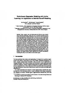
POWERTRAIN MODEL As an example, it is interesting to look at a PSAT parallel configuration model to understand the interest in using a standard format (Figure 1). The driver output is a torque demand at the wheels, which is proportional to an accelerator or brake pedal command. This demand is sent to the powertrain controller (PTC), which decides how each component of the drivetrain should operate. Indeed, we make choices about the blending among the different energy sources and when and how we start the engine or shift a gear. The PTC sends specific commands to the component control unit so that they can be understood by the models. For instance, the PTC
Figure 1. Example of PSAT Powertrain Model
asks for a specific torque to the engine, and the engine control unit (ECU) block within the component control unit transforms the torque into a throttle demand that the engine model can process. Then, the mechanical power from the engine and the electrical power from the motor (via the battery) are summed. In fact, both mechanical and electrical power are used to propel the vehicle. The component’s information is collected (via sensors), and a bus is created (pwt_bus) to enable the system to use the information back in the controller to make the next decision.
COMPONENT MODEL As shown in Figure 2, each component model is saved in one of three specific libraries:
The component model: models the physics of the system. The constraints block: used to define the limits of the component (for instance, the maximum engine torque at the current speed). The signal conditioning block: used to send the proper command to the component in the component control unit (Figure 1).
input/output of the power ports, as shown in Figure 1. The first ports are used for the information:
Input: components commands (on/off engine, gear number, etc.) Output (sensors): simulated measures (torque, rotational speed, current, voltage, etc.)
The second ports carry the effort (e.g., voltage, torque); the last ones carry the flow (e.g., current, speed). This format allows users to select different levels of component models depending upon the goal of the simulation (i.e., if the user is interested in the fuel cell component, he/she can use a very detailed fuel cell model while the rest of the models are based upon lookup tables). It is very important to notice that the first input and output are vectors and can have any desired size: a simple engine model can have only two inputs (such as engine on/off and engine command), while a detailed engine model can have five or more inputs.
The name of the library, as well as each block, also follows naming convention rules based upon the component name ("eng") as well as the model version (1 in our example). ORGANIZATION FORMAT — To easily exchange the models and implement new ones, a common format, based on Bond Graph [4], is used between the
Figure 3. Global Formalism for the I/O of the Models Using Bond Graph USE OF GOTO-FROM FORMAT — As shown in Figure 4, to simplify the component models, we decided to use the GOTO-FROM format. As far as the models are concerned, all of the GOTO-FROM blocks are local and are located at the upper level of the model (no blocks are located in the subsystems). To facilitate the work for Hardware in the Loop (Control Desk access to the parameters and variables by using the Tags), the names of the Tags are defined in accordance with certain rules. Other rules apply when developing a new component model: Figure 2. Example of Component Library — Engine
Colors are used to simplify model understanding: inports are in red, outports in cyan, GOTO-FROM in green, and constants in yellow.
[tx_ratio_hist] gear ratio table
[tx_gear_hist] gear nb
1 gear nb
[tx_trq_in_hist]
[tx_spd_in_hist] torque input
2 T/J in
em
Speed
[tx_inertia_in_hist] Inertia Input
3 spd in
[tx_gear_hist] [tx_ratio_hist] [tx_inertia_in_hist] [tx_inertia_out_hist] [tx_trq_in_hist] [tx_trq_loss_hist] [tx_trq_out_hist] [tx_spd_in_hist] [tx_spd_out_hist]
speed out
tx_gear_hist2bus tx_ratio_hist2bus tx_inertia_in_hist2bus tx_inertia_out_hist2bus 1 tx_trq_in_hist2bus output tx_trq_loss_hist2bus tx_trq_out_hist2bus tx_spd_in_hist2bus tx_spd_out_hist2bus mux_tx
Speed Calculation [tx_spd_out_hist] 3 spd out
speed out torque_loss
[tx_trq_loss_hist]
gear number
[tx_trq_out_hist] input torque
torque_out
Torque calculation
2 T/J out
gear nb Inertia_out Inertia_in
[tx_inertia_out_hist] Inertia Calculation
Figure 4. Example of Transmission Component Model
Three blocks are used within each model to calculate speed, torque, and inertia. Lines to connect the information to the bus are named (“parameter'2bus”). These names are used so that users automatically know where each parameter is located in the buses.
Once the buses are created, users can access the parameters simply by using their names, as shown in Figure 5. For example, if the user wants to access the engine speed (parameter "eng_spd_hist"), he/she will use the parameter "nb_" followed by the name of the parameter. Accessing the wrong information is a major cause for mistakes and, as most simulation model users know, one of the most difficult to find. Another advantage of using this parameterized bus structure is that no major revision of the drivetrain model’s structure is necessary when swapping between engine models with different numbers of output parameters, because the size of the bus is automatically updated. Figure 5. Parameter Access in the Buses
CONTROL STRATEGY PSAT powertrain controllers, which are in charge of commanding the different components, have a generic structure common to all configurations, as shown in Figure 6. By using the accelerator/brake pedals and the
information coming (via sensors) from the component models, we evaluate the constraints of the system, such as the maximum available torque of the engine. We then take those limits into account to define the optimized control strategy, which allows us to use the powertrain
Accelerator pedal
Information from component (sensors)
C O N S T R A I N T S
T R A N S I E N T S
D E M A N D
Commands to components
Figure 6. Powertrain Control Strategy Organization
components to minimize fuel consumption and emissions. Finally, we take the transients into account by defining the actions required to satisfy the control strategy demands. For instance, if the control strategy decides to shift gears with a manual transmission, we have to cut off the engine ignition, declutch, engage the neutral gear, engage the new gear, clutch, and inject once again. These steps have to happen successively and lead to a modification of the demands previously sent by the demand block. Within the PSAT powertrain controller, different strategies can be selected within a particular powertrain model. Indeed, because the strategy has an important impact on the fuel consumption, it is interesting to switch between different control strategies to be able to compare them. To evaluate the impact of these different strategies, we can select and compare them through the graphical user interface. Parameter nomenclature:
The outputs of the constraints block end in “cstr_hist.” The outputs of the demand block end in “dmd_hist” (strategy). The outputs of the transient block end by “trs_hist.” The outputs of the component command block that goes to the component models end by “cmd_hist” (command).
1) Because of its flexibility, PSAT allows users to choose more than 150 pre-selected configurations. When looking at hybrids, it is difficult to talk about a parallel, because there are probably several hundred of them. So we decided to provide a picture of the exact drivetrain configuration (as shown on the upper left). Because the user also has the option of changing the location of the electric motor(s), a popup menu has been added (position 1 to 4). 2) Because of the number of components available in PSAT, it was impossible to keep the list of possible plots in a single popup menu. We decided to have a separate list for each component, as shown on the bottom left. 3) Several other choices were made available to facilitate user's decisions:
USER FRIENDLINESS
GRAPHICAL USER INTERFACE — Development of a graphical user interface (GUI) is very important to facilitate user choices in terms of drivetrain configuration, initialization files, and cycles.
Initialization Window — Figure 7 shows an example of the initialization window.
Checkboxes allow users to choose their particular configurations. Because several levels of modeling can be available for a component (e.g., look-up table, neural network, or physical-based for engine), a new column is used to allow users to choose the version. Question marks allow users to directly open the right part of the documentation to provide information on the different levels of modeling available. A last popup menu has been added to provide information on the technology of the component (e.g., spark ignition [SI] or compressed ignition [CI] for engine). An option to choose between 2WD, 2t2WD, and 4WD configurations has been added. If we can also change any look-up table by scaling the different components, specific parameters can be changed by using the variable list. The parameters are listed by component.
Figure 7. Input for Graphical User Interface
4) The main menu also allows users to:
Change the simulation algorithm (variable or fixed step size); and Choose the units they want on the GUI (e.g., Standard International [SI] or U.S. units).
5) Several other specific windows have been developed to easily and automatically integrate new component models (version) or types without opening any MATLAB m-files. It is our intention that the user can do everything through the GUI without opening even one file. Cycle Choice Window — The second window of the GUI allows users to choose the type of simulation to be performed; in addition to choosing among a large number of driving cycles, simulating the performance of the drivetrains, and conducting a parametric study, users can employ specific tools to run several simulations in a row. These tools are critical because they allow engineers to spend time analyzing results, instead of waiting in front of their computers until the end of a simulation. Users can run dozens of simulations during the night and analyze the results in the morning. When developing a control strategy, engineers always use standard cycles. However, standard cycles have limited benefits because they do not usually allow users to check the system behavior close to its limits (e.g., battery state-of-charge). It is then necessary to validate the strategies by using real trips (about one to two hours long in real time) rather than cycles (10 to
20 minutes long in real time). We have developed an innovative GUI that allows users to build their own cycles, which could be several hours long. Post-Processing Windows — Because of the complexity of hybrid electric vehicles, the post-processing information obtained after each simulation has been completed is crucial. PSAT naturally provides the final results of each simulation and the capability to plot each parameter. Users then have the option of easily comparing, in a couple of clicks, the same parameters from different simulations in order to, for example, study the influence of a powertrain configuration on fuel consumption. But more than the plots, detailed postprocessing data — including energy, power, efficiency, torque, speed, current, and voltage — are very useful to users. Moreover, to better understand and improve the drivetrain control strategy, PSAT provides all of this information for the four different conditions of operation (acceleration/deceleration and charging/discharging). In order to run several simulations in a row and access them later, each simulation is saved by using four different files:
A document, including the initial conditions and the final results; A MAT file with all the variables from the simulation; A file with all the post-processing calculations (e.g., energies, efficiencies); and
An m-file to be able to rerun the exact same simulation.
IMPLEMENTATION OF NEW DATA OR MODELS — Because most simulation tools are developed for outside use, one of the most important characteristics of a tool is the option to easily implement proprietary data sets, component models, or control strategies. Using the structured approach previously described, we developed a specific GUI that enables the user to implement anything without modifying a single line of code, as shown in Figure 8. By using this window, users can add, view, or delete data files, scaling algorithms, calculation files (for preprocessing), or component models, as well as change the picture. Component compatibilities are also taken into account, which is an important but uncommon capability for this type of software. In the PSAT model, both the compatibility with the drivetrain configuration and with other component models are taken into account. For instance, one torque converter can only be used with a specific automatic transmission of an engine technology (or type) with a specific after-treatment. Because software developers cannot expect users to know or remember all the different compatibilities, PSAT makes sure that only compatible choices are available for selection in the input window (Figure 7). COMPARISON OF SIMULATIONS — As previously mentioned, the number of advanced powertrain configurations is almost endless. To be able to make the right decision, users need to be able to easily compare
different options. Several features have been implemented in the code that allow users to run several simulations in a row and later access the results. For the same configuration, users can run several driving schedules in a row, as well as performing parametric studies. To allow comparison among different powertrain or control strategies, we incorporated the ability to automatically create batch runs. This is only possible by saving the simulation parameters as well as the initial conditions and final results. Figure 9 shows an example of a comparison between powertrain options. In that example, we ran a Toyota Prius and a Honda Insight on the Japan 1015 cycle. Each simulation can be accessed through a popup menu, and parameters, such as engine torque (bottom graph), can be compared. The first plot shows the desired and obtained vehicle speeds (m/s), the second one shows the engine torques (Nm) for each configuration. The figure shows that the Toyota Prius requires more torque from the engine than does the Insight because of the lower weight and better aerodynamics of the Insight. COMPARISON BETWEEN SIMULATION AND TEST — In order to be sure we select the right configuration or control strategy, both the component and the drivetrain models need to be validated. Validation is a very important aspect of software development because it demonstrates to users the degree of accuracy of the software. Modeling tools can be validated by using different data sources, including vehicle, component, or drivetrain tests.
Figure 8: Integration of Data and Model
Figure 9. Prius and Insight Simulation Comparison on Japan 1015 Cycle
Argonne used all of these methodologies to validate PSAT. However, although Argonne’s Advanced Powertrain Research Facility (APRF) is sufficient in the two first cases, the development of a specific tool dedicated to prototyping was necessary for drivetrain testing. To answer U.S. Department of Energy (DOE) and FreedomCAR Partnership needs, Argonne developed PSAT-PRO, the extension of PSAT for prototyping. In order to easily compare test and simulation data (from APRF or PSAT-PRO), a specific window has been developed, as shown in Figure 10, to be able to dynamically replay tests, as well as simulation. Simultaneously examining both data sets allows users to process much more information than with static plots. Users can compare — at every sample time — the different powertrain parameters. In this example, the vehicle speed is shown, as well as the engine, motor, and generator maps. The tool allows users to quickly understand where the engine operates and, most importantly, why (i.e., deceleration, acceleration…). In addition to being useful for understanding the control strategy of a particular vehicle from test data, this GUI can also be used to improve a control strategy from simulation.
CONCLUSION Because of the number of possible hybrid architectures, the development of the next generation of vehicles will require advanced and innovative simulation tools. Model complexity does not mean model quality: flexibility, reusability, and user friendliness are key characteristics to model quality. By using a well-defined nomenclature, a structured approach, and an innovative algorithm, we are able to allow users to choose among more predefined drivetrain configurations than any other tool. Easy implementation of component data and models (including handing compatibility issues), as well as control strategies, is possible because we used a unified component model approach and a graphical user interface. Finally, comparison between simulations or between test data and simulation is facilitated by innovative dynamic interfaces. The structured, yet flexible, approach used in PSAT could be used as a base to establish industry standards within the automotive modeling community, where each institution implements its own data or model in a common generic software architecture.
Figure 10. Dynamic Comparison of Test and Simulation — Prius Example
ACKNOWLEDGMENTS This work was supported by the U.S. Department of Energy, under contract W-31-109-Eng-38. The authors would like to thank Bob Kost and Lee Slezak of DOE, who sponsored this activity.
REFERENCES 1. Argonne National Laboratory, PSAT (Powertrain Systems Analysis Toolkit), www.psat.anl.gov, last updated October 15, 2003. 2. Rousseau, A., S. Pagerit, and G. Monnet, “The New PNGV System Analysis Toolkit PSAT V4.1 — Evolution and Improvements,” SAE paper 01-2536, Future Transportation Technology Conference, Costa Mesa, Calif., August 2001. 3. The Mathworks, Inc., Matlab Release 13, User's Guide, 2003. 4. Karnopp, D., D. Margolis, and R. Rosenberg, System Dynamics: A Unified Approach, 2nd edition, John Wiley & Sons, Inc., New York, 1990.
CONTACT Aymeric Rousseau (630) 252-7261 E-mail:
[email protected]