International Journal of Biological and Medical Sciences 1:2 2006
Fingerprint Compression Using Contourlet Transform and Multistage Vector Quantization S. Esakkirajan, T. Veerakumar, V. Senthil Murugan and R. Sudhakar
700,000 pixels and needs about 0.6 Mbytes to store. A pair of hands then requires about 6 Mbytes of storage. So digitizing the FBI’s current archive would result in more than 200 Terabytes of data. Because of data storage requirements and the time needed to send a fingerprint card over a modem, these files must be compressed. Although there are many image compression techniques currently available, there still exists a need to develop faster and more robust algorithms adapted to fingerprints. The currently used fingerprint standard is based on the discrete wavelet transform [3] using the biorthogonal wavelet 7.9. Although the performance of this standard is better than that of the cosine transform based JPEG standard, it still needs enhancements. To achieve better quality, i.e., high peak signal to noise ratio (PSNR) contourlet transform [4] and multistage vector quantization (MSVQ) [5] are considered in this work. Compression can be achieved by transforming the data, quantizing the coefficients obtained during transformation and then encoding the quantized coefficients. To avoid redundancy, which hinders compression, the transform must be atleast biorthogonal and in order to save CPU time, the corresponding algorithm must be fast [6]. The twodimensional wavelet transform satisfies these conditions. Wavelet compression allows the integration of various compression techniques into one algorithm. Recently there has been a wide interest in image representations that efficiently handle geometric structure. One such representation is contourlet transform. The contourlet transform is proposed as a mean to fix the failure of wavelets in handling geometry by the presence of directional vanishing moments in the contourlet frame element. Vector quantization (VQ) is a quantization technique [7] applied to an ordered set of symbols. The superiority of ‘VQ’ lies in the block coding gain, the flexibility in partitioning the vector space, and the ability to exploit intra-vector correlations. MSVQ divides the encoding task into several stages. The first stage performs a relatively crude encoding of the input vector using a small codebook. Then, the second stage quantizer operates on the error vector between the original vector and the quantized first stage output. The quantized error vector provides a refinement to the first approximation. The indices obtained by multistage vector quantizer are then encoded using Huffman coding. The remainder of the paper is organized as follows: Section II focuses on contourlet transform, Section III emphasizes on multistage vector quantization, Section IV deals with the proposed image compression scheme and finally conclusions
Abstact—This paper presents a new fingerprint coding technique based on contourlet transform and multistage vector quantization. Wavelets have shown their ability in representing natural images that contain smooth areas separated with edges. However, wavelets cannot efficiently take advantage of the fact that the edges usually found in fingerprints are smooth curves. This issue is addressed by directional transforms, known as contourlets, which have the property of preserving edges. The contourlet transform is a new extension to the wavelet transform in two dimensions using nonseparable and directional filter banks. The computation and storage requirements are the major difficulty in implementing a vector quantizer. In the full-search algorithm, the computation and storage complexity is an exponential function of the number of bits used in quantizing each frame of spectral information. The storage requirement in multistage vector quantization is less when compared to full search vector quantization. The coefficients of contourlet transform are quantized by multistage vector quantization. The quantized coefficients are encoded by Huffman coding. The results obtained are tabulated and compared with the existing wavelet based ones.
Keywords—Contourlet Transform, Directional Filter bank, Laplacian Pyramid, Multistage Vector Quantization I. INTRODUCTION
F
INGERPRINTS are the ridge and furrow patterns on the tip of the finger and are used for personal identification of the people [1]. Federal Bureau of Investigation (FBI) deals with a massive collection of fingerprint cards, which contains more than 200 million cards and is growing at a rate of 30,000 - 50,000 new cards per day [2]. FBI is digitizing these cards to allow for electronic storage, retrieval, and transmission. Fingerprints are digitized at a resolution of 500 pixels/inch with 256 gray levels. A single fingerprint is about Manuscript received July 3, 2006. S. Esakkirjan is working as a Lecturer, in the Department of Electrical and Electronics Engineering, PSG College of Technology, Peelamedu, Coimbatore-641 004, Tamilnadu, India. (Corresponding author to provide phone: 91-422-2572177; e-mail:
[email protected]). T. Veerakumar is working as a Lecturer, in the Department of Electronics and Communication Engineering, PSG College of Technology, Peelamedu, Coimbatore-641 004, Tamilnadu, India. (e-mail:
[email protected]). V. Senthil Murugan is with Cognizant Technology Solution, Chennai, India. (e-mail:
[email protected]). R. Sudhakar is working as a Lecturer, in the Department of Electronics and Communication Engineering, PSG College of Technology, Peelamedu, Coimbatore-641 004, Tamilnadu, India. (e-mail:
[email protected]).
140
International Journal of Biological and Medical Sciences 1:2 2006
are drawn in Section V. II. CONTOURLET TRANSFORM The Contourlet Transform is a directional transform, which is capable of capturing contours and fine details in images. The contourlet expansion is composed of basis function oriented at various directions in multiple scales, with flexible aspect ratios. With this rich set of basis functions, the contourlet transform effectively capture smooth contours that are the dominant feature in natural images. In contourlet transform, the Laplacian pyramid does the decomposition of images into subbands and then the directional filter banks analyze each detail image as illustrated in Fig .1. The pyramidal directional filter bank (PDFB) [8], was proposed by MinhDo and Vetterli, which overcomes the block-based approach of curvelet transform by a directional filter bank, applied on the whole scale also known as contourlet transform (CT). The grouping of wavelet coefficients suggests that one can obtain a sparse image expansion by first applying a multi-scale transform and then applying a local directional transform to gather the nearby basis functions at the same scale into linear structures. In essence, first a wavelet-like transform is used for edge (points) detection, and then a local directional transform for contour segments detection. With this insight, one can construct a double filter bank structure (Fig.2 (a)) in which at first the Laplacian pyramid (LP) is used to capture the point discontinuities, and followed by a directional filter bank (DFB) to link point discontinuities into linear structures [9]. The overall result is an image expansion with basis images as contour segments, and thus it is named the contourlet transform. The combination of this double filter bank is named pyramidal directional filter bank (PDFB). Fig. 2(a) shows the block diagram of a PDFB. First a standard multi-scale decomposition into octave bands is computed, where the low pass channel is sub-sampled while the high pass is not. Then a directional decomposition with a DFB is applied to each high pass channel. Fig. 2(b) shows the support shapes for contourlets implemented by a PDFB that satisfies the anisotropy scaling relation. From the upper line to the lower line, four reduces the scale while the number of directions is doubled. PDFB allows for different number of directions at each scale/resolution to nearly achieve critical sampling. As DFB is designed to capture high frequency components (representing directionality), the LP part of the PDFB permits subband decomposition to avoid “leaking” of low frequencies into several directional subbands, thus directional information can be captured efficiently. In general, the contourlet construction allows for any number of DFB decomposition levels ‘lj’ to be applied at each LP level ‘j’. For the contourlet transform to satisfy the anisotropy scaling relation, one simply needs to impose that in the PDFB, the number of directions is doubled at every other finer scale of the pyramid. Fig. 2(b) graphically depicts the supports of the basis functions generated by such a PDFB.
Fig. 1 A flow graph of the Contourlet Transform
Fig. 2 (a) Block diagram of a PDFB, and (b) Supports for Contourlets
As can be seen from the two shown pyramidal levels, the support size of the LP is reduced by four times while the number of directions of the DFB is doubled. Combine these two steps, the support size of the PDFB basis functions are changed from one level to next in accordance with the curve scaling relation. In this contourlet scheme, each generation doubles the spatial resolution as well as the angular resolution. The PDFB provides a frame expansion for images with frame elements like contour segments, and thus is also called the contourlet transform. A. Laplacian Pyramid One way of achieving a multiscale decomposition is to use a Laplacian pyramid (LP), introduced by Burt and Adelson [10]. The LP decomposition at each level generates a down sampled low pass version of the original and the difference between the original and the prediction, resulting in a bandpass image as shown in Fig. 3(a). In this figure, ‘H’ and ‘G’ are called analysis and synthesis filters and ‘M’ is the sampling matrix. The process can be iterated on the coarse version. In Fig. 3(a) the outputs are a coarse approximation ‘a’ and a difference ‘b’ between the original signal and the prediction. The process can be iterated by decomposing the coarse version repeatedly. The original image is convolved with a Gaussian kernel [11]. The resulting image is a low pass
141
International Journal of Biological and Medical Sciences 1:2 2006
frequency partition shown in Fig. 5, low frequencies would leak into several directional subbands, hence DFB does not provide a sparse representation for images. To improve the situation, low frequencies should be removed before the DFB. This provides another reason to combine the DFB with a multiresolution scheme. Therefore, the LP permits further subband decomposition to be applied on its bandpass images. Those bandpass images can be fed into a DFB so that directional information can be captured efficiently. The scheme can be iterated repeatedly on the coarse image. The end result is a double iterated filter bank structure, named pyramidal directional filter bank (PDFB), which decomposes images into directional subbands at multiple scales. The scheme is flexible since it allows for a different number of directions at each scale. Fig. 6 shows the contourlet transform of the Fingerprint. Each image is decomposed into a low pass subband and several bandpass directional subbands. It can be seen that only contourlets that match with both location and direction of image contours produce significant coefficients. Thus, the contourlet transform effectively explores the fact, that the edges in images are localized in both location and direction. One can decompose each scale into any arbitrary power of two’s number of directions, and different scales can be decomposed into different numbers of directions. This feature makes contourlets a unique transform that can achieve a high level of flexibility in decomposition while being close to critically sampled. Other multiscale directional transforms
filtered version of the original image. The Laplacian is then computed as the difference between the original image and the low pass filtered image. This process is continued to obtain a set of band-pass filtered images (since each one is the difference between two levels of the Gaussian pyramid). Thus the Laplacian pyramid is a set of band pass filters. By repeating these steps several times a sequence of images, are obtained. If these images are stacked one above another, the result is a tapering pyramid data structure, as shown in Fig. 4 and hence the name. The Laplacian pyramid can thus be used to represent images as a series of band-pass filtered images, each sampled at successively sparser densities. It is frequently
Fig. 3 Laplacian pyramid scheme (a) analysis, and (b) reconstruction
used in image processing and pattern recognition tasks because of its ease of computation. A drawback of the LP is the implicit oversampling. However, in contrast to the critically sampled wavelet scheme, the LP has the distinguishing feature that each pyramid level generates only one bandpass image (even for multi-dimensional cases), which does not have "scrambled" frequencies. This frequency scrambling happens in the wavelet filter bank when a high pass channel, after downsampling, is folded back into the low frequency band, and thus its spectrum is reflected. In the LP, this effect is avoided by downsampling the low pass channel only. B. Directional Filter Bank In 1992, Bamberger and Smith [12] introduced a 2-D directional filter bank (DFB) that can be maximally decimated while achieving perfect reconstruction. The directional filter bank is a critically sampled filter bank that can decompose images into any power of two’s number of directions. The DFB is efficiently implemented via a l-level treestructured decomposition that leads to ‘2l’ subbands with wedge-shaped frequency partition as shown in Fig. 5. The original construction of the DFB involves modulating the input signal and using diamond-shaped filters. Furthermore, to obtain the desired frequency partition, an involved tree expanding rule has to be followed. As a result, the frequency regions for the resulting subbands do not follow a simple ordering as shown in Fig. 4 based on the channel indices. The DFB is designed to capture the high frequency components (representing directionality) of images. Therefore, low frequency components are handled poorly by the DFB. In fact, with the
Fig. 4 Laplacian pyramid structure
either have a fixed number of directions or are significantly over complete.
142
International Journal of Biological and Medical Sciences 1:2 2006
A. MSVQ Encoder In the MSVQ encoder as shown in fig.7, the input vector ‘X’ is quantized with the first stage codebook producing the first stage code vector Q0(X), a residual vector y0 is formed by subtracting Q0(X) from ‘X’. Then y0 is quantized using the second stage codebook, with exactly the same procedure as in the first stage, but with y0 instead of X as the input to be quantized. Thus, in each stage except the last stage, a residual vector is generated and passed to the next stage to be quantized independently of the other stages. MSVQ is an error refinement scheme, inputs to a stage are residual vectors from previous stage and they tend to be less and less correlated as the process proceeds.
Fig. 5 DFB frequency partitioning
Fig. 7 Encoder block diagram of MSVQ
Fig. 6 Contourlet Transform of Fingerprint
III. MULTISTAGE VECTOR QUANTIZATION
B. MSVQ Decoder The decoder as shown in Fig. 8 receives for each stage an index identifying the stage code vector selected and forms the reproduction ‘X’ by summing the identified vectors. The overall quantization error is equal to the quantization residual
In vector quantization, an input vector of signal samples is quantized by selecting the best matching representation from a codebook of ‘2kr’ stored code vectors of dimension ‘k’. VQ is an optimal coding technique in the sense that all other methods of coding a random vector in ‘k’ dimension with a specific number b=kr of bits are equivalent to special cases of VQ with generally sub optimal codebooks. However, optimal VQ assumes single and possibly very large codebook with no imposed constraints in its structure. The resulting encoding and storage complexity, of the order of 2kr, may be prohibitive for many applications. A structured VQ scheme which can achieve very low encoding and storage complexity is MSVQ. In MSVQ, the kr bits are divided between L stages with bi bits for stage ‘i’. The storage complexity of MSVQ is L b ∑ 2 i vectors that can be much less than the complexity of i =1 L
∏2
bi
Fig. 8 Decoder block diagram of MSVQ
= 2 kr vectors for unstructured VQ. MSVQ [13] is a
from the last stage. Sequential searching of the stage codebooks renders the encoding complexity to the storage L b complexity ∑ 2 i . i =1
i =1
sequential quantization operation where each stage quantizes the residual of the previous stage. The structure of MSVQ encoder [14] consists of a cascade of VQ stages as shown in fig. 7. For an L-stage MSVQ, a l th –stage quantizer Ql , l =0,1,2… L − 1 is associated with a stage codebook
Cl contains K l stage code
vectors. The set of stage quantizers equivalent to a single quantizer direct-sum vector quantizer.
IV. PROPOSED SCHEME The proposed algorithm is summarized below. 1. To decorrelate the relationship between pixels, contourlet transform is applied first to all the fingerprints taken. Different directional and pyramidal filter banks are considered for
{Q0,Q1,.......,QL −1} are
Q , which is referred to as the
143
International Journal of Biological and Medical Sciences 1:2 2006
decomposition. This is the initialization stage of the proposed algorithm. 2. Group neighboring contourlet coefficients into one vector. 2 by 2 contourlet coefficients are grouped into a vector. 3. Take the absolute values of all vector components since signs and absolute values of vector components are encoded separately in our algorithm, we consider only the magnitude of each vector component in the refinement process. 4. Find the training vectors for the first layer codebook. This can be done by two different ways. One is to include all training vectors of the first layer, i.e., symbols with norms larger than the first threshold T1. Another is to manipulate the components of vectors, e.g. multiplied by 2 or 4, so that all the vectors fall in the subspace of the first layer. The latter approach contains a much larger training set and richer patterns than the former one. We choose the second method in our coding scheme. 5. Perform multistage codebook training. The codebook training includes: find the centroids of the training set, and the residual code words of the first stage, second stage, and etc. The training method is Lloyd-Max iteration, which is often referred to as Linde, Buzo and Gray (LBG) [15]. In this work we do not design a different codebook for each individual layer. The same codebook is applied to all layers. 6. The indices obtained from Multistage Vector Quantization are encoded by Huffman coding. The proposed scheme uses static Huffman coding where the same Huffman table is used for different fingerprints. This way overhead of sending Huffman tables along with coded data is eliminated.
TABLE I PSNR VALUES FOR WAVELET VS CONTOURLET TRANSFORM FOR ARCH TYPE FINGERPRINT Bpd Filters Wavelet: ‘Haar’ Contourlet: P-filter: ‘Haar’ D-filter: ‘9-7’ P-filter: ‘Haar’ D-filter: ‘pkva’ P-filter: ‘Haar’ D-filter: ‘5-3’ P-filter: ‘9-7’ D-filter: ‘pkva’ P-filter: ‘pkva’ D-filter: ‘9-7’ P-filter: ‘5-3’ D-filter: ‘9-7’ P-filter: ‘9-7’ D-filter: ‘5-3’ P-filter: ‘pkva’ D-filter: ‘5-3’ P-filter: ‘5-3’ D-filter: ‘pkva’
0.125
0.25
0.5
0.75
1.0
25.8820
38.7565
50.5928
54.3465
59.9010
27.7315
40.1037
51.9884
55.5676
62.6486
27.7584
40.0999
51.9807
55.5614
62.6456
26.4390
39.3212
51.3174
54.8794
62.1502
21.6754
28.4383
35.1472
38.7381
41.2961
21.1154
27.8619
34.3806
37.8090
40.1303
22.8744
30.1356
31.9153
35.1001
37.3613
21.4573
28.3826
35.1316
38.7230
41.2917
21.1001
27.8567
34.3795
37.8072
40.1301
22.8840
30.1386
31.9156
35.1000
37.3612
W a ve le t V s Contourle t for Arch type Finge rprint 65 W a ve le t= Ha a r Contourle t= Ha a r + 9-7 Contourle t= Ha a r + 5/3
60
PSNR in dB--->
55 50 45 40 35 30 25 0.1
0.2
0.3
0.4 0.5 0.6 0.7 Bits pe r dim e nsions------>
0.8
0.9
1
Fig. 9 Plot of PSNR Vs bit rate for Arch type fingerprint
V. RESULTS AND DISCUSSIONS We present the encoding results of three different types of fingerprints [16] namely, Arch, Whorl and Tented arch [17]. For simplicity, we have considered only two stages in the multistage vector quantization. The same algorithm can be extended to many stages. As a trial we have tested our algorithm by including three stages in MSVQ for ‘whorl’ type fingerprint. We found that there is an improvement in the quality of the reconstructed image at the expense of execution time. The codes are run on a Pentium IV PC with 256Mb RAM. Table I gives the result of the proposed scheme against wavelet based MSVQ for ‘Arch’ type Fingerprint and the corresponding plot is shown in Fig. 9. In Table I P-filter stands for Pyramidal filer and D-filter stands for Directional filter. From the Table I, we can infer that the proposed scheme outperforms the wavelet based multistage vector quantization. In the case of fingerprint image, the ‘Haar’ and ‘9-7’ as the pyramidal and directional filter combination gives better PSNR result when compared to other pyramidal and
Contourle t for Arch type Finge rprint 45 Contourle t= 9-7+ 5-3 Contourle t= pkva + 5-3 Contourle t= 5-3 + pkva
PSNR in dB--->
40
35
30
25
20 0.1
0.2
0.3
0.4 0.5 0.6 0.7 Bits pe r dim e nsions------>
0.8
0.9
1
Fig. 10 Comparison of bit rate Vs PSNR between different pyramid and directional filters for Arch type Fingerprint
144
International Journal of Biological and Medical Sciences 1:2 2006
TABLE II PSNR VALUES FOR WAVELET VS CONTOURLET TRANSFORM FOR WHORL TYPE FINGERPRINT
Contourle t for W horl type Finge rprint 70 Contourle t= Ha a r + 5-3 Contourle t= pkva + 5-3 Contourle t= 5-3 + 9-7
65 60
Bpd
55
0.25
0.5
0.75
1.0
27.1424
39.3130
51.0576
54.8483
60.6549
27.8948
40.0786
52.0603
55.6817
62.5094
27.8981
40.0896
52.0582
55.6769
62.5085
27.8117
39.9904
51.9785
55.6013
62.4465
27.9788
40.2739
52.3538
55.7253
64.2610
27.2947
39.4134
51.5580
54.9343
63.6097
29.7069
42.0123
54.0421
57.5380
66.1097
TABLE III PSNR VALUES FOR WAVELET VS CONTOURLET TRANSFORM FOR TENTED ARCH TYPE FINGERPRINT
27.8618
40.1528
52.2465
55.6317
64.1534
Bpd
27.2290
39.3447
51.4852
54.8762
63.5566
29.7444
42.0062
54.0574
57.5604
66.1263
Filters Wavelet: ‘Haar’ Contourlet: P-filter: ‘Haar’ D-filter: ‘9-7’ P-filter: ‘Haar’ D-filter: ‘pkva’ P-filter: ‘Haar’ D-filter: ‘5-3’ P-filters: ‘9-7’ D-filter: ‘pkva’ P-filter: ‘pkva’ D-filter: ‘9-7’ P-filter: ‘5-3’ D-filter: ‘9-7’ P-filter: ‘9-7’ D-filter: ‘5-3’ P-filter: ‘pkva’ D-filter: ‘5-3’ P-filter: ‘5-3’ D-filter: ‘pkva’
PSNR in dB--->
Filters Wavelet: ‘Haar’ Contourlet: P-filter: ‘Haar’ D-filter: ‘9-7’ P-filter: ‘Haar’ D-filter: ‘pkva’ P-filter: ‘Haar’ D-filter: ‘5-3’ P-filter: ‘9-7’ D-filter: ‘pkva’ P-filter: ‘pkva’ D-filter: ‘9-7’ P-filter: ‘5-3’ D-filter: ‘9-7’ P-filter: ‘9-7’ D-filter: ‘5-3’ P-filter: ‘pkva’ D-filter: ‘5-3’ P-filter: ‘5-3’ D-filter: ‘pkva’
0.125
35 30 25 0.1
0.2
0.3
0.4 0.5 0.6 0.7 Bits pe r dim e nsions------>
0.125
Wavelet=Haar Contourlet=Haar + 9-7 Contourlet=9-7 + pkva
60 55 50 45 40 35 30
0.2
0.3
0.4 0.5 0.6 0.7 Bits per dimensions------>
0.8
0.9
0.8
0.9
1
Fig. 12 Comparison of bit rate Vs PSNR between different pyramid and directional filters for Whorl type Fingerprint
Wavelet Vs Contourlet for Whorl type Fingerprint
PSNR in dB--->
45 40
65
25 0.1
50
1
Fig. 11 Plot of PSNR Vs bit rate for Whorl type fingerprint
directional filter combinations. The plot of bit rate against PSNR for different pyramidal and directional filter bank is shown in Fig.10. Table II gives the result of the proposed scheme against wavelet based MSVQ for ‘whorl’ type fingerprint and the corresponding plot is shown in Fig.11. The plot of bit rate against PSNR for different pyramidal and directional filters for ‘whorl’ type fingerprint is shown in Fig.12. From the Table II, we can infer that the proposed scheme outperforms the wavelet based MSVQ. In the case of ‘whorl’ type fingerprint, the ‘5-3’and ‘pkva’ as the pyramidal and directional filter combination gives better PSNR result when compared to other pyramidal and directional filter combinations. Table III gives the result of the proposed scheme against wavelet based MSVQ for ‘tented arch’ type fingerprint and the corresponding plot is shown in Fig.13. From the Table III, we can infer that the proposed scheme outperforms the
0.25
0.5
0.75
1.0
27.8779
40.0652
51.6030
55.5409
61.5637
27.9290
40.1262
51.9707
55.6631
62.3710
27.9205
40.1208
51.9595
55.6605
62.3744
27.8300
40.0427
51.8884
55.5895
62.3155
27.1465
39.3296
51.4179
54.9379
63.4569
27.2113
39.5365
51.5463
55.0195
63.5487
28.4193
40.5040
52.5302
56.0321
64.6424
27.9202
40.0989
52.2367
55.7056
64.2819
27.1401
39.4470
51.4635
54.9351
63.4787
28.7065
40.7743
52.8632
56.3000
64.9559
W a ve le t V s Contourle t for Te nte d a rch Finge rprint 65 W a ve le t= Ha a r Contourle t= Ha a r + 9-7 Contourle t= 9-7 + pkva
60
PSNR in dB--->
55 50 45 40 35 30 25 0.1
0.2
0.3
0.4 0.5 0.6 0.7 Bits pe r dim e nsions------>
0.8
0.9
1
Fig. 13 Plot of PSNR Vs bit rate for Tented Arch type fingerprint
wavelet based MSVQ. In the case of ‘tented arch’ type fingerprint, the ‘5-3’ and ‘pkva’ as the pyramidal and directional filter combination gives better PSNR result when
145
International Journal of Biological and Medical Sciences 1:2 2006
Contourle t for Te nte d a rch Finge rprint 65 Contourle t=Ha a r + 5-3 Contourle t=pkva + 5-3 Contourle t=5-3 + 9-7
60
PSNR in dB--->
55 50 45 40 35 30 25 0.1
(a) 0.2
0.3
0.4 0.5 0.6 0.7 Bits pe r dim e nsions------>
0.8
0.9
(b)
1
Fig. 14 Comparison of bit rate Vs PSNR between different pyramid and directional filters for Tented arch type Fingerprint
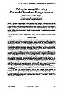
compared to other pyramidal and directional filter combinations which is evident from Fig.14. Fig 15, 16 and 17 shows the original and reconstructed ‘arch’, ‘whorl’ and ‘tented arch’ type fingerprints at different bit rates. The pyramidal and directional filters chosen are ‘53’ and ‘pkva’ respectively. From the figures, it is obvious that as the bit rate increases, the visual quality of the reconstructed image increases which is in accordance with Rate-Distortion theory. The execution time and the PSNR values for different stages in MSVQ is given in Table IV and the corresponding plot is shown in Fig. 18. From the table and figure, it is clear that if we incorporate more stages in MSVQ, the quality of the reconstructed image is improved but the execution time is more. Original image
(c) (d) Fig. 16 Original and decoded 128 x 128 Whorl type Fingerprint (a) Original image (b) bpd=0.125, (c) bpd=0.25, (d) bpd=1.0 using P-filter= ‘5-3’ and D-filter= ‘pkva’
Reconstructed image
(a)
(a) Reconstructed image
(b)
(b) Reconstructed image
(c) (d) Fig. 17 Original and decoded 128 x 128 Tented arch type Fingerprint (a) Original image (b) bpd=0.125, (c) bpd=0.25, (d) bpd=1.0 using P-filter= ‘5-3’ and D-filter= ‘pkva’ (c) (d) Fig. 15 Original and decoded 256 x 256 Arch type Fingerprint (a) Original image (b) bpd=0.125, (c) bpd=0.25, (d) bpd=1.0 using P-filter = ‘5-3’ and D-filter = ‘pkva’
146
International Journal of Biological and Medical Sciences 1:2 2006
TABLE IV CONTOURLET TRANSFORM WITH DIFFERENT STAGES IN MSVQ FOR WHORL TYPE FINGERPRINT Single Stage Two Stage MSVQ Three Stage MSVQ MSVQ Bits per ExecuExecuExecudimensions PSNR tion PSNR in tion PSNR in tion (bpd) in dB time in dB time in dB time in seconds seconds seconds 0.125 17.4918 0.9070 29.7444 1.2350 42.0052 1.4530 0.25 23.6555 0.9220 42.0062 1.2500 60.1104 1.4690 0.5 29.7444 0.9370 54.0574 1.3440 78.0889 1.6100 0.75 33.5023 1.0470 57.5604 1.3750 81.7458 1.7030 1.4060 90.7871 1.8440 1.0 36.0350 1.0620 66.1263
[2]
[3]
[4]
[5]
[6] [7] [8]
[9]
[10]
[11] [12]
[13]
[14]
Fig. 18 Plot of PSNR Vs Execution time for Whorl type Fingerprint
[15] [16]
VI. CONCLUSION In this paper, compression of fingerprints using contourlet transform and multistage vector quantization has been presented. An extensive result has been taken on different types of fingerprints. It can be seen that the PSNR obtained by contourlet transform is higher than that of wavelet transform. Hence, a better image reconstruction is possible with less number of bits, by using contourlet transform. Here, only four filter combinations are considered. We are currently pursuing with other filter combinations. The experimental results reveal the fact that MSVQ is suitable for low bit rate image coding. The proposed scheme yields encoding outputs of good quality around 0.5 bits per dimension (bpd) and very good results at around 1 bpd. This scheme can easily be extended to include more stages in MSVQ to improve the output image quality.
[17]
ACKNOWLEDGMENT The authors wish to thank their teachers Dr. S. Jayaraman, Dr. N. Malmurugan for the continued support and encouragement. They also thank their present institution where they are working. REFERENCES [1]
Pennebaker W.B. and Mitchell J.L, JPEG-Still Image Data Compression Standards. Van Nostrand Reinhold, 1993.
147
C.M. Brislawn, J.N. Bradley and R.J. Onyschczak and T. Hopper, “The FBI Compression Standard for Digitized Fingerprint Images,” in 1996 Proc. SPIE, vol.2847, pp. 344-355. M.Antonini, M.Barlaud, P. Mathieu, and I.Daubechies, “Image coding using wavelet transform,” IEEE Trans. Image Proc, pp.205-220, Apr.1992. M. N. Do and M. Vetterli, “The contourlet transform: an efficient directional multiresolution image representation,” IEEE Trans. Of Image Processing, vol.14, no.12, pp. 2091-2106, Dec. 2004. B.H.Juang and A.H.Gray, “Multiple stage vector quantization for speech coding,” in 1982 Proc. IEEE Int.Conf.Acoust, Speech, Signal Processing (Paris, France), pp.597-600. K.P. Soman and K.I. Ramachandran, Insight into Wavelets from Theory to Practice, Prentice Hall India, New Delhi, 2002, ch.9. A.Gersho and R.M. Gray, Vector Quantization and Signal Compression. Boston, MA: Kluwer, 1992. M. N. Do and M.Vetterli, “Pyramidal directional filter banks and curvelets,” in 2001 Proc. Of IEEE Int. Conf. on Image Proc, vol.3, pp.158-161, Thessaloniki, Greece. D.D. Y. Po and M. N. Do, “Directional multiscale modeling of images using the contourlet transform,” IEEE Trans. on Image Processing, to appear, Jun. 2006. P. J. Burt and E. H. Adelson, “The Laplacian pyramid as a compact image code,” IEEE Trans. on Commun. vol. 31, no. 4, pp. 532-540, 1983. M. N. Do, “Directional Multiresolution Image Representations,” Ph.D.Thesis, EPFL, Lausanne, Switzerland, Dec. 2001. R. H. Bamberger and M. J. T. Smith, “A filter bank for the Directional decomposition of images: theory and design,” IEEE Trans. on Signal Processing, vol. 40, no. 4, pp. 882-893, Apr. 1992. Jayshree Karlekar, P.G. Poonacha and U.B. Desai, “Image Compression using Zerotree and Multistage Vector Quantization”, ICIP, Vol.2, pp.610, 1997. Hosam Khalil, Kenneth Rose, “Multistage vector quantizer optimization for packet networks,” IEEE Trans. Signal Proc. Vol. 51, No.7, pp.18701879, July 2003. Y. Linde, A. Buzo and R.M.Gray, “An algorithm for vector quantizer design,” IEEE Trans. Commun. Vol.28, pp.84-95, Jan.1980. R. Sudhakar, R. Karthiga and S. Jayaraman, “Fingerprint compression using Contourlet Transform with Modified SPIHT algorithm”, IJECE, vol.5, No.1, pp.3-10, Winter-Spring 2006. www.biometrics.cse.msu.edu/fingerprint.html.