Key words: Finite element analysis, flat footing, foundation, shell footing ... jointly integrated to act as combined or raft foundation. The hyperbolic paraboloid ...
Journal of Computer Science 2 (1): 104-108, 2006 ISSN 1549-3636 © Science Publications
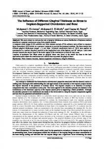
Finite Element Study Using FE Code (PLAXIS) on the Geotechnical Behavior of Shell Footings Bujang B.K. Huat and Thamer A. Mohammed Department of Civil Engineering, Universiti Putra Malaysia, 43400 Serdang, Selangor, Malaysia Abstract: This study describes a study on the geotechnical behavior of shell footing using a nonlinear finite element analysis with a finite element code, PLAXIS. The shell footing is found to have a better load carrying capacity compared with the conventional slab/flat footing of similar cross sectional area. The FE analysis also showed a reasonably good agreement with the laboratory experimental results. The effect of adding edge beams at the bottom of the shell footings has been studied numerically and found to be beneficial in increasing the load carrying capacity of the footing. The effect of increasing the embedment ratio is found to increase the load carrying capacity of the shell footings. Key words: Finite element analysis, flat footing, foundation, shell footing INTRODUCTION Concept of shell is not new in foundation design, considering construction in past with inverted brick arch foundation in this category. The use of inverted brick arches as foundation has been in practice in many parts of the world for a long time. Shells in modern foundation engineering however are relatively still newcomer. Shell footings have been found to be economical foundations in areas having high material to labor cost ratio[1,2]. Shell foundation is economical and has greater load carrying capacity compared with flat shallow foundations. Moreover, shells are essentially thin structures, thus structurally more efficient that flat structures. This is an advantage in situation involving heavy super structural loads to be transmitted to weaker soils. Shell footing is limited to a few geometries, such as conical, pyramidal, hypar and spherical footings and these footings are shown in Fig. 1-4, respectively. The conical shell (Fig. 1) is the simplest form of shell, which can be employed in foundation engineering due to its singly curved surface. Due to its circular plan, the use of conical shell footing is restricted to an isolated footing only. A pyramidal shell (Fig. 2) is a combination of four inclined trapezoidal plate elements. Since the pyramid can be portrayed as square or rectangular in plan, multiple units of pyramidal shell foundation can be jointly integrated to act as combined or raft foundation. The hyperbolic paraboloid (hyper) shell (Fig. 3) is a doubly curved anticlastic shell, which has translation as well as ruled surfaces. This footing has potential to be employed in a wide range of application in foundation engineering. Spherical shells (Fig. 4) do not posses straight-line property, which makes its construction more complex. It can only be used as an isolated footing.
Fig. 1: Typical detail of conical footing
Fig. 2: Typical detail of pyramidal footing Experimental and theoretical investigations reported the evaluation of structural behavior for shell structure, such as the membrane stresses,
Corresponding Author: Bujang B.K. Huat, Department of Civil Engineering, University Putra Malaysia, 43400 Serdang, Selangor, Malaysia
104
J. Computer Sci., 2 (1): 104-108, 2006 conducted a finite element analysis for conical shell footing to study the effects of increasing soil modulus. The present study aims to study the interaction between the shell footing and soil using a non-linear finite element analysis code, PLAXIS. The effects of adding edge beams at the bottom of the footing and depth of embedment of the footings, on the load carrying capacity of the footing are investigated using the FE analysis. FINITE ELEMENT MODEL The shell footings and the soils were modeled and analyzed using the commercial finite element software PLAXIS, developed by PLAXIS BV, Netherlands. The program ‘PLAXIS’ uses the incremental tangent stiffness approach in the analysis, in which the load is divided into a number of small increments, which are applied simultaneously. During each load increment, the stiffness properties appropriate for the current stress level are employed in the numerical analysis. Experimental results from earlier work of AbdelRahman[8] were used to validate the finite element modeling of the present study. Three types of footing models; flat/slab footing, triangular shell footing 1 and triangular shell footing 2 are selected for the analysis and compared with the experimental results obtained earlier by AbdelRahman[8]. The cross sections of the model footings are shown in Fig. 5.
Fig. 3: Typical detail of hypar footing
Fig. 4: Typical detail of spherical footing bending moments, shear and deflections. For theoretical analysis, mathematical formulations, namely finite difference technique and finite elements analyses were utilized. In some studies, linear Winkler and Pasternek soil model was used to simulate the soil behavior under different types of shell foundations. In few studies, the distribution of the soil contact pressure on shell footing was also examined. The results indicated a non-uniform contact pressure distribution along the soil-shell interface. However, the structural design of shell foundation is currently based on membrane theory, in which the soil contact pressure distribution is assumed to be uniform[3-6]. The ultimate strengths of the shell footings were also investigated both experimentally and theoretically; and comparisons were performed with conventional flat foundation. All studies reached the same conclusion concerning the saving achieved in the construction materials and the good structural performance of the shell footing. The findings of these investigations have direct impact on the construction cost of shell footings as compared to the conventional flat counterparts[7]. Abdel-Rahman[8], Hanna and Abdel-Rahman[9,10] reported experimental results on conical shell footings on sand for plain strain condition. Maharaj[11]
Nb. Dimensions in m Fig. 5: Details of half sections for flat and shells of triangular 1 and triangular 2 model footings
105
The cross sectional properties of the three models shown in Fig. 5 are listed in Table 1. These properties are used as input for modeling the footings by the FE program PLAXIS. The soil is modeled using the MohrCoulomb model; the properties of which is shown in Table 2.
J. Computer Sci., 2 (1): 104-108, 2006 Table 1: Cross-sectional properties of the finite element model footings Properties\Types
Flat
Triangular 1
Triangular 2
Cross Section Area (m2) Moment of Inertia, I (mm4) Modulus of Elasticity, Esh (kN m 2) Poisson Ratio, Material Type Flexural Rigidity, EI Axial Stiffness, EA
0.0032 4.27E-7
0.00328 4.77E-7
0.00453 6.034E-7
209E6 0.3 Elastic 89.173 668800
209E6 0.3 Elastic 99.696 7482200
209E6 0.3 Elastic 126.11 9457250
Table 2: Soil (sand) properties - Mohr- Coulomb model Properties Value Unsaturated Unit Weight 17 Saturated Unit Weight 18 Permeability Coefficient, kx=ky 1.00 Young’s Modulus, E 4E4 Poisson Ratio, 0.3 Cohesion Coefficient, c 0.001 Friction Angle, φ 33.68 Dilatancy Angel, 2.00 Material Model Mohr-Coulomb Model
Unit kN m 3 kN m 3 m day 1 kN m 2 none kN m 2 Degree Degree none
(a) Generated mesh for triangular 1 shell footing
The geometry of the mesh for plain strain condition is symmetrical about the centerline, therefore only one half of the cross section passing through the axis of symmetry of the footing is considered. The nodes along the bottom and both sides of the section are considered as pinned supports, i.e., no movement is allowed in both vertical and horizontal directions, which called in the program as Standard Fixities. The soil and the footing were modeled using 15-noded linear strain quadrilateral elements ‘LSQ’ with quadratic variations for the displacement along the sides of the element. Smaller size element for the soil was selected in the vicinity of the footing where the variations of stresses and strains are expected to be more significant. Figure 6 shows the typical generated and deformed mesh. Figure 7 shows the load–settlement curves of the finite element (FE) models. Superimposed in Fig. 7 is the load–settlement of the laboratory experiment. In general there is a good agreement between the FE model and that of the laboratory. However, the results of the FE analyses are slightly higher than that of the laboratory experiments. The difference is about 11, 15 and 25% for the flat, triangular shell 1 and triangular shell 2 footings, respectively. This is inherent since the FE analysis is done in two dimensions while the experimental study is for a 3 D model. However both the laboratory and FE models clearly show that load carrying capacity of the triangular shell, with a similar cross sectional area, is higher than the flat footing. Shell footing ensures better enclosibility of the soil inside the space of the footing by preventing the soil from flowing outward. This can be very significant, particularly when the soil is poor. A similar conclusion is made by Hanna and Abdel-Rahman[9,10].
(b) Deformed mesh for triangular 1 shell footings Fig. 6: Typical generated and deformed mesh
Fig. 7: Load-settlement curves of the FE experimental model of the flat/slab triangular shell footings
and and
FE STUDY ON THE EFFECT OF EDGE BEAMS AND DEPTH OF EMBEDMENT The presence of an edge beam at the toe of the shell would reduce the soil pressure and increase the bearing capacity[12]. To examine this, as well as the effect of embedment ratio, a finite element analysis using the finite element code, PLAXIS, is done to study the load-settlement behavior of shell footing model with different edge beams. Five types of edge beam 106
J. Computer Sci., 2 (1): 104-108, 2006 Table 3: Cross-sectional properties of new shell footing models Properties\Types Type1 Footing Type2 Footing Cross Section Area (m2) 0.25 0.44 4 Moment of Inertia, I (mm ) 4.0E-3 7.0E-3 Modulus of Elasticity, Esh 2E7 2E7 (kN/m2) Poisson Ratio, 0.3 0.3 Material Type Elastic Elastic Flexural Rigidity, EI 8000 14E4 Axial Stiffness, EA 5.0E6 8.8E6
Type3 Footing 0.329 5.54E-3
Type4 Footing 0.388 6.5E-3
Type5 Footing 0.346 5.0E-3
2E7
2E7
2E7
0.3 Elastic 11E4 6.5E6
0.3 Elastic 13E4 7.76E6
0.3 Elastic 10E4 6.9E6
Fig. 10: Load -settlement curve at the shell footing with and without the edge beam
Nb. All the dimensions in m Fig. 8: Details of half sections of shell footings with various edge beams
Fig. 11: Effects of the various configuration of edge beam on the shell footing
Nb. All the dimensions in m Fig. 9: Type 1 footing with various embedment ratios, R
Fig. 12: Effect of the embedment ratio on the load carrying capacity of the shell footings
configurations were considered, namely Type 1, 2, 3, 4 and 5 and these are shown in Fig. 8. Type 1 footing is a shell footing without the edge beam; Type 2 footing is with a double edge beam; Type 3 footing is with single
edge beam; Type 4 footing is with a vertical edge beam; and Type 5 footing is with inclined edge beam. 107
J. Computer Sci., 2 (1): 104-108, 2006 The effect of adding edge beams at the bottom of the shell footings has been studied numerically and found to be beneficial in increasing the load carrying capacity of the footing. Fully embedded shell footing is shown to have a better load carrying capacity compared with the footing with no embedment.
Embedment ratio, R is 1 for fully embedded footing and R = 0 for footing with no embedment. In this case only the Type 1 footing was studied. The cross sections of the models are shown in Fig. 9. Table 3 summarizes the cross sectional properties of the model footing. The sandy soil is modeled using the Mohr Coulomb model, as shown Table 2. Figure 10 shows the effect of adding an edge beam at the bottom of shell footing on load-settlement curve of the footing. Footing of Type 1 (i.e. without edge beam) and Type 2 (with double edge beam) are considered in this case. The initial portion of the two curves overlaps each other up to load of about 100 kN. After this load, the load carried by shell footings with the double edge beam is significantly higher than the footing without the edge beam. This shows that there is a significant improvement in settlement-load carrying capacity of the footing when added with the edge beam. Figure 11 shows the comparison of the load carrying capacity of the shell footings with the various edge beam configurations, i.e. for Type 2, 3, 4 and 5. As shown footing with the double edge beam (Type 2), single edge beam (Type 3) and inclined edge beam (Type 5) show better load-settlement characteristics compared with the footing having vertical edge beam (Type 4). Figure 12 shows the effect of embedment ratio on the load-settlement behavior of the shell footings. From Fig. 12 it can be seen that the load-settlement curve for the three-embedment ratios (i.e. from fully embedded to no embedment) overlaps each other until about 300 KN. After this load, the load carried by the embedded shell footing is more than the footing without embedment. This shows the benefit of fully embedded the footing on the load carrying capacity of the shell footing.
REFERENCES 1.
Kurian, N.P., 1977. Economy of hyperbolic paraboloidal shell footings. Geotech. Eng., 8: 5359. 2. Kurian, N.P., 1982. Modern FoundationsIntroduction of Advanced Techniques. Tata McGraw-Hill, New Delhi. 3. Fareed, A. and R.H. Dawoud, 1979. Cylindrical shells on elastic foundation. World Cong. Shell and Spatial Structures. Madrid, Spain, 3: 5.33-5.46. 4. Melerski, E., 1988. Thin shell foundation resting on stochastic soil. I. Structural Eng. ASCE., 114: 2692-2709. 5. Paliwal, D.N. and R.N. Rai, 1986. Shallow spherical shell on Pasternak foundation subjected to elevated temperature. J. Thin-walled Structures,5: 343-349. 6. Paliwal, D.N. and S.N. Sinha, 1986. Static and dynamic behaviour of shallow spherical shells on Winkler foundation. J. Thin-walled Structures, 4: 411-422. 7. Kurian, N.P., 2000. Shell Foundations–The Asian Choice. New Building Materials and Construction World. 8. Abdel-Rahman, M., 1996. Geotechnical behavior of shell foundations. Ph.D Thesis, Department of Civil Engineering, Concordia University, Montréal, Canada. 9. Hanna, A.M. and M. Abdel-Rahman, 1998. Experimental investigation on shell foundations on dry sand. Can. Geotech. J., 35: 828-846. 10. Abdel-Rahman, M. and A.M. Hanna, 1990. Ultimate bearing capacity of triangular shell footings on sand. J. Geotech. Eng. ASCE., 116: 1851-1863. 11. Maharaj, D.K., 2004. Finite element analysis of conical shell foundation. Elect. J. Geotech. Eng., 9A: Paper No. 348. 12. Jain, V.K., G.C. Nayak and O.P. Jain, 1977. General behavior of the conical shell foundation. Proc. 3rd Intl. Symp. Soil Structure Interaction. University of Roorkee. India, 2: 53-61.
CONCLUSION A non-linear finite element analysis using finite element code, PLAXIS, was carried out to study the geotechnical behavior of the shell footings. From the finite element results, it was found that the shell footing had a better load carrying capacity compared with the slab/flat footing for a similar cross sectional area. The FE analysis also showed a reasonably good agreement with the laboratory experimental results; with a discrepancy of within 11 to 25%.
108