Flexible Arrays of Inexpensive Network (FAIN): Toward global parallelism in the Internet to satisfy future traffic growth Katsushi Kobayashi National Institute of Advanced Science and Technology (AIST), Akihabara, Tokyo, JP
[email protected] ABSTRACT In this study, we present the flexible arrays of inexpensive network (FAIN) architecture: it can be used to maximize parallelism in network systems in order to satisfy future Internet traffic growth. Although the “parallel-in-global” approach used in FAIN overcomes a constraints of serial interfaces, the performance of applications with s small stream can be preserved. FAIN provides thousand of isolated virtualized slices, and enables incremental extensions in the capacity of router systems. FAIN also provides multiple level subscriber differentiation, and power consumption optimization according to the traffic.
Categories and Subject Descriptors C.2.1 [Computer-Communication Networks]: Network Architecture and Design—Packet-switching networks
General Terms Design, Performance
Keywords Network architecture, Virtualization
1. INTRODUCTION A study of Internet have revealed that the traffic is increasing at the rate of 40% per year, and this growth is expected to continue for the next 5 or more years[7]. We require network technologies, routers and circuits that can satisfy future growth. It is strongly desired that parallelism in network systems be improved in a manner similar to that in other computing technologies.
Permission to make digital or hard copies of all or part of this work for personal or classroom use is granted without fee provided that copies are not made or distributed for profit or commercial advantage and that copies bear this notice and the full citation on the first page. To copy otherwise, to republish, to post on servers or to redistribute to lists, requires prior specific permission and/or a fee. ReArch’08, December 9, 2008, Madrid, SPAIN Copyright 2008 ACM 978-1-60558-234-4/08/0012 ...$5.00.
This is because beyond a certain limit, the device speed does not increase significantly with higher clock due to the increased power consumption at such higher clocks. A noteworthy study conducted approximately 10 years ago predicted that parallelism would be increasingly used in network systems in order to deal with the rapid growth of traffic in the future [10]. It was also predicted that the rate of packet reordering would increase due to the use of parallelism. Therefore, the study recommended that transport stacks and network applications should be more resilient against reordered packet streams. The prediction of the increased use of parallelism in network systems has proved to be accurate, and the recommendation against reordering has been implemented in the form of SACK: in fact variants of SACK have been implemented in most modern OSs[13]. Recent router systems have been highly parallelized through generations of architectural evolution, i.e., from a shared bus with a shared CPU, to cross bar switches with a dedicated CPU per line card[15, 17]. For example, as a result of massively parallelism, high-end routers used today employ multi-shelf configurations due to a huge capacity fabric system consisting of a lot of multistage fabrics. [6, 4]. In the case of the maximum configuration of a Juniper T-640, 5 rack shelves are required to accommodate 32-port OC768 interfaces, and 1 shelf is required only for the fabric used to interconnect the shelves. In the case of CISCO CRS1, 80 shelves are required for 1,152 OC768 interfaces, and 8 shelves are required only for the interconnect. With regard to circuit technologies, although WDM has been extensively deployed, it only provides multiple dedicated existing circuits with parallelism in a physical layer, since the development of optical interface devices for router systems has not followed the maximum capacity of WDM circuits’. The use of parallelism for achieving an improvement in the link layer speed has been introduced recently: in this regard, WDM is a candidate media in 100 Gb Ethernet standardization[3]. However, despite of the prediction of increased parallelism, it has been observed that portion reordering has not increased[14]. This is because, most users have been
avoiding reordering since it negatively impacts the TCP and application throughput. Nowadays, packet reordering is considered to be a significant router performance metric in the same manner as the routing capacity [16]. Therefore, current parallelism approaches are restricted to the local component level, i.e., “parallel-in-a-box” or “parallel-in-a-fiber”, since the circuit interface is still constrained being serial due to the strong requirement for preventing packet reordering in a stream from application. Furthermore, even when a router is designed based on “parallel-in-a-box”, significant efforts are required to ensure that reordering does not occur within the box. We believe that such serial constraints narrow the design space for network components: a global parallel architecture may be a solution for handling expected the traffic growth. Furthermore, the multi-shelf router systems mentioned above require a large amount of electric power – as 1 MW in the case of CISCO CRS-1 with the maximum configuration. The power consumption will increase with the growth in traffic, and this might lead to a crisis in Internet infrastructure. If the power consumption is determined by serial constraints, the elimination of the constraints may contribute to a reduction in the power consumption. In this paper, we describe how parallelism can be enhanced from “in-a-box” to “global” without significantly affecting the performance currently enjoyed by users. We present a new network virtualization architecture called Flexible Arrays of Inexpensive Network (FAIN) in which a network is broken down into thousands of equivalent, parallel, and isolated network slices. An end-to-end stream is handled within one FAIN slice, thus preventing reordering. We present a router cluster that can be created using only small routing components by means of isolation between slices. We also present a dynamic power saving mechanism by which a part of the router cluster can hibernate depending on the traffic. Our study confirms that FAIN can be used to realize multiple level service differentiation depending on subscriber’s charge within inter-domain as well as intradomain. The rest of paper is organized as follows, Section 2 describes our network virtualization approach wherein a network is broken down into small slices. Section 3 presents an implementation design for the network virtualization, and its applications. In Section sec:related, we discuss related studies. Finally, we presented our conclusions in Section 5.
2. NETWORK VIRTUALIZATION In order to realize “parallel-in-global” in the Internet, over the Internet, we propose the use of the FAIN architecture. FAIN preserves the packet switch archi-
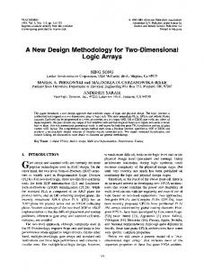
tecture, and comprises virtually sliced parallel networks and MUX-DEMUX edges. Further, it does not require any modification of the end system. In FAIN, an entire network is virtually sliced into multiple networks (Fig 1). All network components except end systems, i.e., routers and links, have to be sliced into multiple virtual components. In FAIN, one Slice A
Slice A
Slice A
Slice B
Slice B
Slice B
Slice C
Slice C
Slice C
Slice D
Slice D
Slice D
Router 1
Router 2
Router 3
(A)
Slice A
Slice A
Slice A
Slice B
Slice B
Slice B
Slice C
Slice C
Slice C
Slice D
Slice D
Slice D
Cluster 1
Cluster 2 (B)
Cluster 3
Figure 1: (A) Network comprising “parallel-ina-box” routers. (B) Network based on “parallelin-global” architecture.
control plane, i.e., routing table, is shared among all slices (Fig 2). The network topology of the virtual slice does not differ from that of other slices, as well as from that of the original network before slicing. A data plane of a virtual network slice comprises the virtual forwarding engine of the router and the virtual link: both of these is isolated with other slices. Therefore, a packet should not be passed across different slices. Virtualized FAIN device arrays are allocated to one or more physical component(s) by taking into account the performance and resources, i.e., forwarding engine sub-array to router chassis, and virtual links to a physical one. Further, there is no interaction between the FAIN physical devices since the slices are isolated. The FAIN component capacity can be increased by simply adding physical device units. In order to realize flexible matching between the virtual forwarding engines and the physical components, a large number of slices should be used. Note that we suggest number of 802.1q supported VLAN, 4,096, is an appropriate example for the number of slices. A FAIN network edge component, i.e., a router accommodating some subscribers, can access every slice. In the case of a packet from a network to a subscriber, the FAIN edge does not consider the slice information of an egress packet, and simply forwards it to the subscriber side. Conversely, in the case of a packet from a subscriber to a network, the FAIN edge router dispatches an ingress packet on a virtual slice in accordance with an ISP ’ s policy, as mentioned in later. With regard to parallelism in FAIN, both the distribution
I/F A
Control VFE:1 VFE:2
I/F B
.. .
VFE:1000 FAIN Router
Figure 2: FAIN routing cluster architecture. Both physical interfaces A and B contain thousand logical circuits. The FAIN router comprises routing controller and thousand virtual forwarding engines. The solid arrows on the left-hand side represent data plane flows, and the dotted ones on right-hand side represent interaction between the controller and the virtual forwarding engines.
and aggregation phases are implemented at the FAIN subscriber edge. The overhead of FAIN aggregation is negligible because the interactions between slices are restricted to a minimum. Moreover, the isolation between each virtual forwarding engine eliminates the reordering caused by parallelism. Thus, if a FAIN edge dispatches ingress packets of the same stream to the same slice, the packet reordering possibility is suppressed within the virtual forwarding engine itself. Note that in order to reduce the stream identification overhead at the FAIN edge, only one slice is typically allocated for a subscriber. Since a FAIN network component can comprise more than one physical device and a packet from the same host can be tied to a single slice, the network throughput from a host is bounded by the limits of the physical device. For example, when a FAIN link is formed by aggregating 10 1-GbE links, the throughput is limited to 1 Gbps instead of 10 Gbps when using a 10 GbE link. If a subscriber cannot be satisfied the bottleneck caused by multiplexed physical device bottleneck, the ISP allows multiple slice access to the subscribers as compensation for the higher tariff. We consider a couple of use-cases when a subscriber requires higher throughput. The first case is assumed to be the most common type by ISPs; an networked service provider would like to gather a large number of access from consumer clients in order for own business model, such as Google, Youtube, and Yahoo. In such cases, the bandwidth for each consumer client is averaged because the service provider
has to accommodate a large number of clients simultaneously. If the service provider binds each client to one slice in its own slice-set, the data packets for the client are kept within the same slice. In another case, the ISP has to provide sufficient bandwidth among a few subscriber’s sites, such as corporate branches or LHC data service sites. A higher throughput can be achieved by using the multiple stream technique and multiple slice access in a manner similar to that in the former case. Multiple stream implementations such as GridFTP are already available. In the case of a single unmodifiable stream application, a pair of middle-boxes, e.g., WAN accelerators, is required to demultiplex and multiplex a stream. The maximum data rate of a stream corresponds to the server interface bandwidth; nowadays, the data rate is typically 10 Gbps. It would not be difficult to create a middle box whose bandwidth performance is several times that of the latest server interface.
3.
FAIN IMPLEMENTATION AND APPLICATION
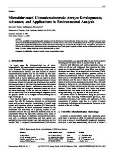
To realize the end-to-end slices of FAIN, a slice identification field is required in the packet header of the network layer. The slice identifier enables that subscribers assigned more than one slice can dispatch a stream to an appropriate slice based on their own policy, such as to maximize the utilization of the assigned slice sub-array. If the underlying device supports multiple virtualized devices and if each FAIN slice is assigned to a different virtual device, such as tagged VLAN in 802.1q, the re-dispatch process in a virtual forwarding engine can be eliminated. Note that a 20-bit flow label field is defined in the IPv6 header, in the network layer, to enable a router to identify an end-to-end stream sequence[11]. The IPv6 flow label also shares the same function as that of the FAIN virtualization identifier, such as preventing reordering even in a parallel approach with a locking the stream into a specific engine. However, in contrast to the IPv6 flow label value being given by the end-host, the FAIN virtualization identifier is provided at the ISP edge. Therefore, the FAIN edge should not modify this field in the current IPv6 specifications. In the daily traffic cycle of Internet backbones, there exists a large gap between the peak and the off-peak traffic – as much as 50% during off peak hours due to the dependence of the traffic on social activities [5]. This suggests that the power consumption of a router system can be reduced during off-peak hours without degrading the performance. Fig. 3(A) shows the router architecture using three stage fabrics. Only the second stage switch (S2) components can hibernate during lower traffic load, and the rest of the components must continue working, because each physical forwarding engine and stage switch (S1, S3) is bounded to different physical interface(s). On the basis of studies conducted
on power consumption in routing systems, less than a quarter of the total excepting the loss is consumed by switch fabrics even including all stages [9]. Thus, the power consumption associated with this router architecture is limited. In a FAIN routing system architecture, as Fig. 3(B), all the interfaces are accommodated by components that correspond to S1 and S3. In the FAIN architecture, if slice allocation to physical devices is performed dynamically by considering the traffic load, forwarding engines, consuming half of the total power, can hibernate along with S2. There is a large potential of power reduction in FAIN routing systems. It should be noted that the number of physical devices required to optimize the throughput and the power consumption can be determined on the basis of the previous traffic statistics.
Supply Loss &Blowers: 33%
Control Plane:10.5% Buffers: 3.5%
FE: in 1
S1
S2
S3
FE: out 1
FE: in 2
S1
S2
S3
FE: out 2
FE: in 3
S1
S2
S3
FE: out 3
FE: in 4
S1
S2
S3
FE: out 4
Hibernatable SW Fabric: 14.5%
This power reduction approach is similar to the server virtualization that multiple virtual servers are accommodated with smaller number of server chassises[8]. When the server load increases, a part of the virtual servers will be migrated to a stand-bye chassis. FAIN links to be multiplexed have to accommodate different sub-arrays of virtual slices. A coordination mechanism is required to interconnect two FAIN routing systems with multiplexed links so that every slice meets the corresponding one. Although we will not discuss this mechanism in detail in this paper, the coordination can only be completed by a local negotiation between the routers. If the number of multiplexed devices on adjacent FAIN components is the same, we can simply connect them one by one. Otherwise, a complicate wiring procedure is required due to the isolated physical physical devices, in addition to the slice coordination mechanism. Further, in case of combining the wiring with the dynamic slice allocation, an additional circuit switch device is required between the forwarding engines and the switches (S1 and S3) accommodating interface(s) (Fig. 4). Although the switch is certainly an overhead for the FAIN router, an affordable and low powered physical layer switch device can be used, such as the electronic patch panel with optical cross connect by Calient or Glimmerglass [1, 2] .
Forwarding Engine: 33.5%
Routing Cluster A
Routing Cluster B
I/O: 6.5%
(A)
Slice: 1-250
Slice: 1-333
Slice: 251-500
Slice: 334-666
Slice: 501-750
Supply Loss &Blowers: 33%
Control Plane:10.5%
Slice: 667-1000
S1,S3
Slice: 751-1000
FE: in/out, S2
Electronic Patch Panel
Electronic Patch Panel
FE: in/out, S2
S1,S3
Buffers: 3.5% Forwarding Engine: 33.5%
S1
FE:in
S2
FE:out
S3
S1
FE:in
S2
FE:out
S3
S1
FE:in
S2
FE:out
S3
S1
FE:in
S2
FE:out
S3
Hibernatable
Figure 4: Interconnect routing clusters having different number of engine with link aggregation. The electronic patch panel devices link the FAIN slice to corresponding forwarding engine and switch. The abbreviations of subcomponents correspond to those shown in Fig. 3.
SW Fabric 14.5% I/O: 6.5%
(B)
Figure 3: (A) An existing router architecture with multi-stage fabrics and the break down of power consumption. (B) A physical architecture for the FAIN routing system and its breakdown. The grey areas in the both represents partial hibernation, when traffic is less. Note that all the components represent physical ones, and not virtual components in FAIN architecture.
Dynamic FAIN slice allocation can decrease the cost of the routing system by reducing the standby facility in redundant configurations. Although redundancy in a routing system typically requires a full set standby system called 1+1, the modularity of the FAIN cluster routing system enables other approaches such as N+1 redundancy to provide only 1/N subsets of the active, or a reduced operation that isolates broken modules (Fig. 5). In the N+1 redundancy case shown in Fig. 5(A), for the first switch accommodating from slice 1 to 333, the packet data for the first device are diverted to the fourth device for stand-bye. In the reduced case
in (B), the packet data is dispersed to the remaining working devices.
Slice: 1-333 Slice: 334-666 Slice: 667-1000 Slice: Standby
(A)
Slice: 1-333 Slice: 334-666 Slice: 667-1000
(B)
Figure 5: Redundancy configurations in the 3parallelled FAIN routing system, (A) N+1, and (B) reduced. When the first device for slice 1333 is non-functional, normal packet flow (shown in the dotted arrows) are diverted to other device(s) (shown by the solid arrows).
In the above discussion, the throughput is bounded by the performance of each FAIN physical device , not that of each virtual slice. However, if the ISPs provide more sophisticated services such as fairness among FAIN slices, it can be realized inexpensively. This is because the number of FAIN slices that require a corresponding queue is fixed and limited. With this “stochastic” fairness per slice granularity, a subscriber who can send traffic to more slices has the potential to obtain greater throughput; for example, if A and B can access 1 and 10 slices, respectively, A ’s traffic has 10 times the opportunity that B ’s traffic has. Therefore, an ISP can offer a more diverse tariff structure using FAIN instead of the tariffs as the choice of just two classes. In addition, this throughput difference based on the accessible number of slices is effective even for inter-domain operations in the case of preserving a slice. Although we do not consider different routing topologies with multiple slices in the above discussion, multiple topologies with FAIN can offer new traffic engineering services. If an ISP operator prefers to shift a part of the traffic from a specific link to another, the operator manually assigns a larger cost, nearly infinity, to some portion of the slice array. Generally, the current traffic
engineering approach controls an ISP ’s backbone traffic by increasing the state in the routers, for example, by announcing more specific prefixes, or by establishing a virtual path between ISP edges using tunnel or MPLS. From the viewpoint of the number of states in a router, traffic engineering using multi-topology routing with FAIN slices is essentially not complicated. Traffic engineering using FAIN slices has an advantage against existing approaches in that the ISP operator can manage traffic with finer granularity because the granularity corresponds to the number of FAIN slice arrays. The FAIN architecture can be used to supplement the efforts of ISPs in building network infrastructure. A higher modularity in the FAIN routing system enables upgrades to the bandwidth capacity by the incremental installation of devices. For an increase in the bandwidth, different routing system architectures have must be used due to the cost and performance tradeoffs . However, since the devices used in a FAIN array are enough even with moderated performances, the device architecture of the routing system can be unified. The device standardization by meant of a unified architecture could suppress the cost and accomplish total investment protection for ISPs and allow the relocation of the core router device into edges.
4.
RELATED STUDIES AND SERVICES
The GENI project plans to create a virtualized network slice using a similar virtualization technique[12]. The objective of this project is to provide a dedicated network slice for each specific research project. This implies that different slices will have different policies. In contrast, a FAIN slice does not mean a specific policy. The differences between the policies are in terms of the number of accessible slices. Most network virtualization studies have focused on providing an application-optimized network. Some studies have attempted to overcome the restrictions of the network topologies and policies used by ISPs by using overlay or tunnel techniques. The FAIN approach does not have such objectives. However, if the semantics of a FAIN slice is agreed among the ISPs and subscribers, a network optimized for a specific purpose can be realized. An optimized network can be constructed by the collaboration of the ISP and the subscriber, and not by the subscribers themselves. Some proposals have been presented to realize a multilevel IP network service using IP header fields, such as ToS routing and Diffserv. These approaches can provide a few service classes because only a limited number of priority fields are available in the IP header. The virtual slice architecture shown in this paper enables a greater number of services, although larger number of routing tables for specific services is required in addition with a table the sharing of all FAIN slices. In case of parallel
physical devices, the specific services can be allocated to different devices. The routing table for each devices can be suppressed. For example, if the ISP provides 1,000 special services in addition with generic service, the required number of table in each engine is only 11 in 100 parallel case instead of 1,001 in serial. We believe that the size of routing table is not a critical issue in a moderated router system as compared with a high-end router due to commoditized devices and an affordable system cost. MPLS have been well deployed in many ISPs for providing label switched paths among corporate sites for VPN, because VPN service is a better revenue source. The network slice architecture in FAIN has better affinity for label switched path in MPLS, because the both architectures are similar in terms of providing a network subset as isolated slices or paths. In case of establishing an MPLS path, the FAIN/MPLS edge assigns a new path to a virtual slice. The data accommodated by the MPLS path is handled by a specific physical device, since a virtual slice is locked on a specific physical device. As a result, FAIN parallelism is not disadvantageous to MPLS services, and advantages of FAIN architecture, such as power saving, forwarding capacity scalability, and routing table suppression in specific services can be obtained.
5. CONCLUSION We have presented the FAIN network architecture, which provides thousands of virtual slices for realizing a scalable network architecture. We have discussed the potential of this system by using applications derived by FAIN. The FAIN architecture does not provide a sustainable solution for the exponential growth in traffic. However, if we can successfully implement a scalable network system architecture by using only typical technologies, along with routers and links, we can probably satisfy future networking traffic growth. Further, we have just presented the concept of FAIN and its applications. We have to verify the feasibility and the scalability with a prototype implementation or or by using other methods.
Acknowledgments The author thank the ReArch’08 reviewer for useful inputs. The author acknowledges partial support from New Energy and Industrial Technology Development Organization (NEDO).
6. REFERENCES [1] Calient Networks. http://www.calient.com/. [2] Glimmerglass. http://www.glimmerglass.com/. [3] IEEE P802.3ba 40Gb/s and 100Gb/s Ethernet Task Force. http://ieee802.org/3/ba/index.html.
[4] T-series Routing Platforms: System and Packet Forwarding Architecture”, Juniper Networks. Juniper Networks, 2002. [5] Report on Network Neutrality. Working Group on Network Neutrality, Ministry of Internal Affairs and Communications, JAPAN, 2007. [6] Cisco CRS-1 Carrier Routing System 16-slot Line Card Chassis System Description. Cisco Systems, 2008. [7] Cisco Visual Networking Index - Forecast and Methodology, 2007―2012. Cisco Systems, 2008. [8] Xen Architecture Overview. Ver. 1.2. http://www.xen.org/, 2008. [9] J. Baliga, R. Ayre, K. Hinton, and R. Tucker. Photonic Switching and the Energy Bottleneck. Photonics in Switching, 2007, pages 125–126, 2007. [10] J. Bennett, C. Partridge, and N. Shectman. Packet reordering is not pathological network behavior. IEEE/ACM Transactions on Networking (TON), 7(6):789–798, 1999. [11] S. Deering and R. Hinden. RFC2460: Internet Protocol, Version 6 (IPv6) Specification. Internet RFCs, 1998. [12] L. P. Ed. GENI Facility Design. GENI Design Document 07-44, GENI Planning Group, April 2007. [13] S. Floyd, J. Mahdavi, M. Mathis, and M. Podolsky. RFC2883: An Extension to the Selective Acknowledgement (SACK) Option for TCP. RFC Editor United States, 2000. [14] S. Jaiswal, G. Iannaccone, C. Diot, J. Kurose, and D. Towsley. Measurement and classification of out-of-sequence packets in a tier-1 IP backbone. IEEE/ACM Transactions on Networking (TON), 15(1):54–66, 2007. [15] N. McKeown. Fast Switched Backplane for a Gigabit Switched Router. Business Communications Review, 27(12):1–30, 1997. [16] M. Przybylski, B. Belter, and A. Binczewski. Shall we worry about packet reordering. Computational Methods in Science and Technology, 11(2):141–146, 2005. [17] G. Varghese. Network Algorithmics: An Interdisciplinary Approach to Designing Fast Networked Devices. Morgan Kaufmann, 2005.