synchronizing the floor texture tracker from two cameras mounted on the ..... prediction is close to the actual position of the feature, the correlation process will take care ..... that is maintained after a change in the orientation, which is the primary ...
Floor texture visual servo using multiple cameras for mobile robot localization
323
17 x
Floor texture visual servo using multiple cameras for mobile robot localization Takeshi Matsumoto, David Powers and Nasser Asgari
Flinders University Australia
1. Introduction The study of mobile robot localization techniques has been of increasing interest to many researchers and hobbyists as accessibility to mobile robot platforms and sensors have improved dramatically. The field is often divided into two categories, local and global localization, where the former is concerned with the pose of the robot with respect to the immediate surroundings, while the latter deals with the relationship to the complete environment the robot considers. Although the ideal capability for localization algorithms is the derivation of the global pose, the majority of global localization approaches make use of local localization information as the foundation. The use of simple kinematic models or internal sensors, such as rotational encoders, often have limitations in accuracy and adaptability in different environments due to the lack of feed back information to correct any discrepancies between the motion model and the actual motion. Closed loop approaches, on the other hand, allow for more robust pose calculations using various sensors to observe the changes in the environment as the robot moves around. One of these sensors of increasing interest is the camera, which has become more affordable and precise in being able to capture the structure of the scene. The proposed techniques include the investigation of the issues in using multiple off-theshelf webcams mounted on a mobile robot platform to achieve a high precision local localization in an indoor environment (Jensfelt, 2001). This is achieved through synchronizing the floor texture tracker from two cameras mounted on the robot. The approach comprises of three distinct phases; configuration, feature tracking, and the multicamera fusion in the context of pose maintenance. The configuration phase involves the analysis of the capabilities of both the hardware and software components that are integrated together while considering the environments in which the robot will be deployed. Since the coupling between the algorithm and the domain knowledge limits the adaptability of the technique in other domains, only the commonly observed characteristics of the environment are used. The second phase deals with the analyses of the streaming images to identify and track key features for visual servo (Marchand & Chaumette, 2005). Although this area is a well studied in the field of image processing, the performance of the algorithms are heavily influenced by the environment. The last phase involves the techniques for the synchronizing multiple trackers and cameras.
324
Robot Localization and Map Building
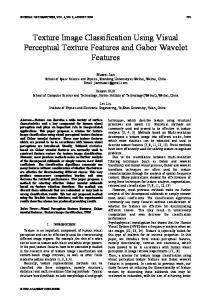
2. Background 2.1 Related work The field of mobile robot localization is currently dominated by global localization algorithm (Davison, 1998; Se et al., 2002; Sim & Dudek, 1998; Thrun et al., 2001; Wolf et al., 2002), due to the global pose being the desired goal. However, a robust and accurate local localization algorithm has many benefits, such as faster processing time, less reliability on the landmarks, and they often form the basis for global localization algorithms. Combining the localization task with image processing allows the use of many existing algorithms for extracting information about the scene (Ritter, & Wilson, 1996; Shi & Tomasi, 1994), as well as being able to provide the robot with a cheap and precise sensor (Krootjohn, 2007). Visual servo techniques have often been implemented on stationary robotics to use the visual cues for controlling its motion. The proposed approach operates in a similar way, but observes the movement of the ground to determine the pose of itself. The strategy is quite similar to how an optical mouse operates (Ng, 2003), in that the local displacement is accumulated to determine the current pose of the mouse. However, it differs on several important aspects like the ability to determine rotation, having less tolerance for errors, as well as being able to operate on rough surfaces. 2.2 Hardware The mobile robot being used is a custom built model to be used as a platform for incrementally integrating various modules to improve its capabilities. Many of the modules are developed as part of undergraduate students' projects, which focus on specific hardware or software development (Vilmanis, 2005). The core body of the robot is a cylindrical differential drive system, designed for indoor use. The top portion of the base allows extension modules to be attached in layers to house different sensors while maintaining the same footprint, as shown in Fig. 1.
Fig. 1. The robot base, the rotational axis of the wheels align with the center of the robot The boards mounted on the robot control the motors, the range finding sensors, as well as relaying of commands and data through a serial connection. To allow the easy integration of off-the-shelf sensors, a laptop computer is placed on the mobile robot to handle the coordination of the modules and to act as a hub for the sensors.
Floor texture visual servo using multiple cameras for mobile robot localization
325
2.3 Constraints By understanding the systems involved, the domain knowledge can be integrated into the localization algorithm to improve its performance. Given that the robot only operates in indoor environments, assumptions can be made about the consistency of the floor. On a flat surface, the distance between the floor and a camera on the robot remains constant. This means the translation of camera frame motion to robot motion can be easily calculated. Another way to simplify the process is to restrict the type of motion that is observed. When rotation of the robot occurs, the captured frame become difficult to compare due to the blending that occurs between the pixels as they are captured on a finite array of photo sensors. To prevent this from affecting the tracking, an assumption can be made based on the frame rate, the typical motions of the mobile robot, life time of the features, and the position of the camera. By assuming that the above ideas amounts to minimised rotation, it is possible to constrain the feature tracking to only detect translations.
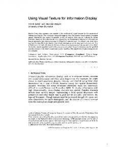
3. Camera configuration 3.1 Settings The proposed approach assumes that the camera is placed at a constant elevation off the ground, thus reducing the image analysis to a simple 2D problem. By observing the floor from a wider perspective, the floor can be said to be flat, as the small bumps and troughs become indistinguishable. Measuring the viewing angle of the camera can be achieved as per fig. 2, which can be used to derive the width and height of the captured frame at the desired elevation. This information can be used to determine the elevation of the camera where the common bumps, such as carpet textures, become indistinguishable. A welcome side-effect of increasing the elevation of the camera is the fact that it can avoid damages to the camera from obstacles that could scrape the lens.
Fig. 2. Deriving the viewing angle, the red line represents the bounds of the view Since the precision of the frame tracking is relative to the elevation of the camera, raising the height of the camera reduces the accuracy of the approach. There is also an additional issue to consider with regards to being able to observe the region of interest in consecutive frames, which also relates to the capture rate and the speed of the robot. Resolving the capture rate issue is the simplest, as this also relates to the second constraint, which states that no rotation can occur between the frames. By setting the frame rate to be as fast as possible, the change between the frames is reduced. Most webcams have a frame rate
326
Robot Localization and Map Building
of around 30Hz, which is fast enough for their normal usage. In comparison, an optical mouse may have a frame rate in the order of several thousand frames per second. This allows the viewing area to remain small, which leads to the optical mouse being able to capture a very small and detailed view of the ground. Although this difference places the webcam at some disadvantage, the increased viewing area allows the option of increasing the speed of the robot or reducing the search area for the tracking. Since the tracking of the region of interest must be conducted reliably and efficiently, the speed of the robot must be balanced with the search area. Although this relationship can be improved with an implementation of a prediction algorithm to prune some of the search area, it is important to note the worst case scenarios instead of the typical cases as it can potentially hinder the other modules. Since the motion blur causes the appearance of previously captured region of interest to change, it is desirable to reduce the exposure time. In environments with dynamically changing lighting conditions, this is not always plausible. This issue is enhanced by the fact that indoor ambient lighting conditions do not permit for much light to be captured by the camera, especially one that is pointing closely to the ground. A simple strategy to get around this issue is to provide a permanent light source near by. Out of several colours and lighting configurations, as shown in fig. 3, the uniformly distributed white light source was selected. The white light source provides a non-biased view of the floor surface, while the uniformly distributed light allows the same region to appear in a similar way from any orientation. To obtain the uniformly distributed light, the light was scattered using a crumpled aluminium foil and bouncing the light against it.
Fig. 3. Colour and shape of light source, left image shows various colours, while the right shows the shape of light The majority of this flickering from the indoor lights can be eliminated by adjusting the exposure time. However, there is a related issue with sunlight if there are windows present, which can result in significantly different appearances when in and out of shadows. A simple way to solve this is to block the ambient light by enclosing the camera and light source configuration. This can be a simple cardboard box with a slight gap to the ground, enough to allow rough floor textures to glide underneath without hitting it. One other important settings is with regards to the physical placement of the camera. Since the approach requires the view of the ground, the placement of the camera is limited to the outer borders of the robot, inside the core body, or suspended higher or further out using a
Floor texture visual servo using multiple cameras for mobile robot localization
327
long arm. The use of an arm must consider the side effects like shaking and possible collision with obstacles, while placing the camera inside the main body restricts the distance to the ground. This can severely reduce the operation speed of the robot and also make the placement of the light source difficult. Another issue to consider is the minimum focal distance required on some webcams, which can sometimes start at around 9 cm. This leaves the option of placing the camera on the outer perimeter of the robot, which allows enough stability, as well as some protection from collisions using the range finders. The camera has been currently placed at the minimum focal distance of the camera, which is at 9 cm from the ground. 3.2 Noise characteristics With the camera configured, filters can be put in place to remove artefacts and enhance the image. There are many number of standard clean-up filters that can be applied, but without knowing the type of noise the image contains, the result may not be as effective or efficient in terms of processing cost. There are many different sources of unwanted artefacts, including the lens quality, the arrangement and quality of the photo sensors, and the scatter pattern of the light from the ground. Many of these errors are dependant on the camera, thus require individual analysis to be carried out. One of the most common artefacts found on webcams is the distortion of the image in the outer perimeters, especially on older or cheaper cameras. In some of the newer models, there is a distortion correction mechanism built into the camera driver, which reduces the warping effect quite effectively. Without this, transformations are required in software to correct the warping by first measuring the amount of the warp. Although this calibration process is only required once, the correction is constantly required for each frame, costing valuable processing time. By knowing the characteristics of the robot, such as the speed and the area viewed by each frame, it is possible to identify regions that will not be used. This information allows portions of the captured image to be discarded immediately, thus avoiding any processing required to de-warp the region. The effects of the lens distortion is stronger in the outer regions of the frame, thus by only using the center of the image, the outer regions can simply be discarded. The regions towards the center may also be slightly warped, but the effect is usually so small that corrections involve insignificant interpolation with the neighbours that it can simply be ignored. When observing the streams of images, it was noted that the speckles of noise were more noticeable in certain regions of the image, as well as when certain colours were being displayed. To investigate this further, the characteristics of the photo-sensors on the cameras were determined when observing various colours. The first of these tests involved the identification of the noise prone or defective regions. Since the gain and contrast settings on the camera can shift or trim the intensity value, the two extreme ends of the intensity scale were chosen. By saturating the camera with a bright light source, it was quite easy to capture a uniform white image. However, capturing a completely black image proved to be slightly more difficult due to the camera not updating when no light was observed. To get around this issue, slightly over half of the view was blocked to capture the behaviour for one side, then repeated for the other side before they were merged. The experiment showed that there was a significant fluctuation in the intensity when observing a dark image compared to a bright image, which did not seemed to be affected by the random fluctuation at all when saturated.
328
Robot Localization and Map Building
The noise characteristics of the black image can be seen in fig. 4, which shows distinctive patterns and positions of where the noise occurs. The duration of the sampling was set to 1,000 frames.
Fig. 4. Noise characteristics, left shows the average, middle shows the maximum, and the right shows the standard deviation To explore the idea of intensity based noise, a second experiment was carried out by displaying a gradient of white to black and observing the amount of fluctuation detected at the various intensities, as shown in fig. 5. The base intensity was determined by the average intensity of the pixel, which was taken over 1,000 frames. The trend shows the relationship between the base intensity and the amount of fluctuation that is encountered. The waves that can be observed is due to the bands that can be seen in the captured image, as well as artefacts from the codec, which will be discussed later. The relationship allows a general model to be constructed for determining the expected noise at a particular intensity. An interesting observation that was made was that the noise caused small fluctuations from the intended intensity, thus allowing the possibility of thresholds to determine if the change in the intensity is due to noise or change in the scene.
Fig. 5. Noise level against intensity, the grey scale image in the top right is the image captured by the camera The last of the noise to be considered is the radial bands that can form due to the arrangement of the light source and the dispersion of the light on reflective surfaces, as shown in fig. 6. The left image shows the original snapshot of a table top, the middle image
Floor texture visual servo using multiple cameras for mobile robot localization
329
shows the stretched version across the full intensity range, while the right image shows the standard deviation, which has also been stretched. The bands that can be seen is the camera's tendency to approximate to the surrounding colour, which occurs as part of the codex.
Fig. 6. Radial intensity shift, this noise often occurs on glossy surfaces 3.3 Image filter The first type of filters to be investigated is the range modifiers, which controls the minimum and the maximum intensities, which indirectly shifts the intensities depending on the position or the captured intensity. Since the maximum intensity could be reached, there is no need to modify this intensity value. However, the minimum value was often not zero for many of the pixels, thus required some further thought. The minimum value may be related to the issue with not being able to capture a pitch black image or residuals and noise generated within the hardware to not allow the distinction between pitch black and almost pitch black objects. Since the minimum value is quite small, often being less than 1/64th of the full range, the significance of this offset is not an important issue to warrant the costly operations required to process it. With regards to the radial shift in the intensity, it is possible to determine if a correction is required by observing a steady increase in the intensity value towards the center of the image. However, it is better to prevent the issue from occurring than correcting it, thus the light source can be better configured to scatter the light more evenly. A commonly used filter to clean up the sensor noise is a spatial or temporal filter to blend the neighbouring pixel's intensities. This reduces the random noise due to the object's size and position consistency across multiple frames. One of the major drawbacks of this approach is its behaviour to blur the whole the image since the blending is applied in inappropriate places that portray different objects. In this particular application, the usability of these filters are made even more difficult by the fact that there are very small patterns present on the floor and the constant motion the camera. The last filter to be considered is one related to the codec induced artefact, which has resulted in the colour bands, as well as the grid pattern shown during earlier experiments. The Moving Pictures Experts Group codec used by the cameras perform a compression algorithm where the image is broken up into small squares, then are simplified as a combination of simple patterns before being heavily compressed by removing the insignificant patterns, especially the more complex ones. Because this process operates independently of the other squares, the continuity between the squares are lost and the inter square subtleties are often lost. Fig. 7 is a zoomed image of a carpet, which illustrates the block formation with a size of 4 by 4 pixels. After some experiments, it was observed that the compression factor, which contributed to how much of each square is smoothed, increased with higher capture resolutions to maintain the data rate going between the device and the processor.
330
Robot Localization and Map Building
Fig. 7. Zoomed image of the carpet, the blocks from the codec is clearly visible Instead of using a large spatial filter to remove the blocks from showing, like a Gaussian blur filter, a carefully weighted custom filter has been developed to blend between the squares, as well as smoothing between the inner 2 by 2 blocks that have formed. The weighting used between the pixels were chosen by observation, but manages to remove the majority of the grid formation, as shown in fig. 8. The weights that are shown are used in the following algorithm to evaluate the new intensity, where the number for the thick blue line is A, the number for the medium line is B, and I represents the intensity: L = A, if i%4 = 0; B, if i%4 = 2; 0, otherwise R = A, if i%4 = 3; B, if i%4 = 1; 0, otherwise U = A, if j%4 = 0; B, if j%4 = 2; 0, otherwise D = A, if j%4 = 3; B, if j%4 = 1; 0, otherwise (1) Ii,j = (L * Ii-1,j + R * Ii+1,j + U * Ii,j-1 + D * Ii,j+1 + 4 * Ii,j) / (4 + L + R + U + D) The current implementation makes use of only one of the above filters, which is the block removal filter with a weight of 1 and 0.25 for A and B respectively.
Fig. 8. Block formation removal, the numbers on the line represents the corresponding weight for the interpolation
Floor texture visual servo using multiple cameras for mobile robot localization
331
4. Floor feature tracking 4.1 Feature detection Although the area feature tracking is a well studied, many of the attributes depend greatly on the specific domains, thus it is important to incorporate the extra criterion or constraint into the feature tracking process. One of the key considerations to make for this application is the lifetime of the features, as they are only required in the immediately subsequent frame. It is possible to store these features for a longer period in case the robot travels slower than expected, to correct any ambiguous tracking of features, or to capture a landmark for the purpose of global localization. However, maintaining the extra tracker increases the search area, reduces the speed of the robot, as well as introducing more processing tasks for the system. This constraint means that a new feature candidate is required at each cycle, which places a greater emphasis on quickly identifying a unique feature. To determine the effectiveness of the features, a score must be evaluated for the candidates to select the best feature within the current view. An important criteria for the feature is to be able to distinguish the same set of pattern in the subsequent frame, thus must consist of a uniqueness measure as well as a consistency measure, which means the intensity pattern should not be too difficult to distinguish if the pattern appears slightly differently due to blurring or sub-pixel motion. Since the change in the appearance is kept small due to the short interval between the frames, more emphasis is required for the uniqueness factor as the floor texture often contains repeated patterns and lacks the variety of intensities found in scenes of other image processing scenarios. Using the intensity value, it is possible to determine the fluctuation from some set value, such as the standard deviation score, to determine how different the region is compared to the surroundings. The uniqueness score only needs to be with respect to the immediate surroundings, as they are only maintained for one cycle. This means the average value should also be derived dynamically. The region being considered can range from the feature itself, the whole region being considered for the candidates, or the viewing area including regions that may or may not be traversed in the future. A much simpler way to score is a simple accumulation of the pixel intensities within the region of interest. This allows the feature to be summarised with just one parse and can easily identify the brightest or the darkest region. However, this can thus lead to reduced reliability in terms of lack of consistency over time due to noise and the amount of similarity there is with respect to the surroundings. An alternate way to evaluate the score is to use the difference in the intensity with the neighbours, such that the edge image is used instead of the intensity. Since the boundary is shared between two pixels, the edge score should not be considered on a per-pixel basis, but at a per-boundary basis. As the intensity difference scores are repeatedly used, a second image can be formed consisting of the change in the intensities. Once the edge map is derived, it can be re-used for other image processing tasks. The candidates that are considered to be the feature should avoid bad patches of flooring that are not distinctive enough while being mindful of the processing load. Since the pattern on the floor cannot be pre-determined, the scanning sequence for candidates is usually set to a raster pattern. Using this sequence, the change in the score can be evaluated by observing the difference between the previous candidate and the current candidate. This is made possible by the fact that the scores for each pixel, or the boundary, are independent of each
332
Robot Localization and Map Building
other. With this in mind, the scan only needs to consider three cases, as illustrated in fig. 9, to sequentially determine the score of the current candidate.
Fig. 9. Difference in the score, only the regions that enter and leave the window are updated The approach showed a speed up from 3.21 ms to 2.04 ms when performing the standard deviation algorithm using a 16 by 16 grid for the feature size in an search area of 8 by 8 positions. The time was determined from 500 cycles of feature candidate selection. As eluded to earlier, the uniqueness score is the most important aspect of the feature selection. Evaluating the effectiveness of this score can be conducted by observing the distribution of the score across the potential range and also on the distance between the adjacent scores. Table 1 summarises the results using the same condition as the above experiment, where the uniqueness is the average percentage rank in terms of finding the feature with the greatest difference in scores with the neighbours. Algorithm
Carpet
Vinyl
Time Uniq. Time Uniq. (ms) (%) (ms) (%) max(ΣI)
2.33
91.23
2.27
97.45
min(ΣI)
2.31
73.23
2.41
89.06
max(Σ|Ix,y – Iave (all)|)
3.9
99.67
3.63
97.54
max(Σ|Ix,y – Iave (view)|)
3.81
96.66
2.61
95.55
max(Σ|Ix,y – Iave (feature)|)
4.09
97.1
3.01
88.05
max(Σ|Ix,y – Ix+1,y| + |Ix,y – Ix,y+1|)
3.37
65.58
3.85
37.12
Table 1. Performance of scoring algorithms, the uniqueness score differed greatly with different implementations It was interesting to observe that the uniqueness of a brighter region was more distinctive than darker regions. This may be due to the level of noise encountered at various intensities or the size of the bright and dark regions. As expected, the naïve approaches were not au very successful in identifying unique regions. Interestingly, the approaches using the difference in the intensities also did not perform well due most likely to the repetitive nature of the floor texture.
Floor texture visual servo using multiple cameras for mobile robot localization
333
Out of the three standard deviation approaches, the one including the surrounding regions performed slightly better than the others. The algorithm performed well on both surface types that were tested, while the processing time did not differ too greatly. When observing the ranking of the scores, it was noted that the majority of the best candidates were either the highest or lowest scoring candidate, mostly due to the fact that only one distance is used. One enhancement which was made is to evaluate not only the maximum, but to evaluate the top two and bottom two before selecting the one with the greatest difference to the second highest or lowest score. The last of the issues to be considered is the shape and size of the features that are tracked. While the size is generally dependent on the processing capability and the amount of uniqueness that is present on the floor, the shape can be used to exploit any known configuration of the texture pattern to improve the effectiveness of the feature. To investigate the effects of different shapes and sizes, several arrangements were constructed. Some of the surfaces that the robot could travel on contains streaks rather than random or spotty patterns. By using a rectangular shape that is aligned with the streak, it increases the chance of seeing the ends of the streak while minimising the processing of the uniform region between the streaks. Another arrangement that is used is a square, but with the central portion being removed. This arrangement was considered after observing that the carpet texture contained regions where the intensity did not differ greatly, such as the portion at the tip of each bundle of threads. The last arrangement is where the pixels of interest are separated and form a sparse grid formation. This arrangement allows a wider area to be covered with a small number of pixels being considered. Fig. 10 illustrates the various sizes and shapes that were considered as the feature.
Fig. 10. Feature shapes, the red region represents the viewing area of the ground The experiment was conducted in a similar way to the earlier tests, but the number of candidates was increased to 256. The scoring algorithm that was used was the standard deviation algorithm across the viewable area. The results, as shown in table 2, indicate the dramatic effect in the processing time when the number of pixels being considered increased, while the uniqueness score was quite high for the majority of the cases. One of the reasons for the high uniqueness score is from deciding between the maximum or minimum score, as described earlier, when selecting the feature.
334
Robot Localization and Map Building Algorithm
Carpet
Vinyl
Time Uniq. Time Uniq. (ms) (%) (ms) (%) 8x8 square
2.98
98.07
5.78
92.23
16x16 square
5.63
99.65
4.05
98.97
24x24 square
18.06 99.84 17.39 95.73
32x32 square
32.95 99.79 30.07 99.43
16x8 rectangle
3.13
99.54
5.92
92.58
24x16 rectangle
7.86
98.78
5.62
99.18
16x16 – 8X8 donut
3.09
99.7
7.56
99.68
24x24 – 8X8 donut 17.03 99.65 16.68 85.59 24x24/2 spaced
3.32
62.5
3.96
92.76
32x32/2 spaced
6.97
99.72
6.37
99.3
32x32/4 spaced
2.81
99.86
3.12
97.94
Table 2. Comparison of shapes, the square performed just as well as customised shapes Although the uniqueness is not the highest, the 16 by 16 square was chosen as the feature dimension, due to the potential speed-up. The average intensity is derived during the image buffer copying process, thus saving some computation in traversing the image again. 4.2 Feature tracking The basic sequence of tracking requires iterating over all candidate locations and determining the difference in the appearance with the stored feature. Due to the limited processing time, this operation must be carried out as efficiently as possible. Given that the tracking is of physical objects, their motions will be continuous. Even when the motion is represented using discrete amounts, the smoothness between the frames can be used to predict the location of the feature in the current frame (Kalman, 1960). The basis of the motion prediction uses the motion vector from the previous cycle and appends the acceleration and the current motor command it is executing. This simple model can be evaluated very quickly, but relies heavily on accuracy of the previous motion that was determined. Since the motion prediction only guides the search area, as long as the prediction is close to the actual position of the feature, the correlation process will take care of correcting the error in the prediction. Determining the motion vector is as simple as using the previous motion that was determined after the feature was found. The acceleration is derived by taking the difference between the motion vectors, but does not consider the motor's characteristics in the current implementation. The motion command to the motors is buffered due to the slight delay in executing and completing the motion. Given that the motion vector and acceleration already captures the majority of the robot motion, the motor command is currently only used to assist when the robot starts moving from a stationary position. The initial acceleration of the robot is very small, thus the magnitude of this adjustment is currently set to be only one pixel. To verify the accuracy of the motion prediction, the error in the distance between the
Floor texture visual servo using multiple cameras for mobile robot localization
335
prediction and the correlated position was plotted, as shown in fig. 11. The experiment was carried out with the robot moving semi-randomly on a carpet surface for a period of approximately 2 minutes with a search area of 16 by 16 pixels. The types of motion included accelerating to full velocity, turning, reversing directions, and others which tested the extreme conditions in which the robot would operate. The results show that the prediction was quite close to the actual feature position with one very interesting result, which showed that a single pixel error was more common than a perfect match. This may be due to the acceleration always being delayed by one cycle or the frequent occurrences of sub-pixel motion. The plot also gives an idea as to how big the search area must be, since no match was found with a distance greater than 10 pixels away from the prediction, it is possible to reduce the search area as long as the types of motion for the robot has been fully explored.
Fig. 11. Accuracy of prediction, the algorithm predicts the motion quite well Given that the motion prediction is quite effective in finding the approximate location of the feature, it would be beneficial to make use of this when searching for the feature. A simple optimisation that can be implemented is by setting a threshold score that halts the computation of the correlation score if a better solution has already been found. Using a raster scan pattern to search for the feature does not fully utilise the sequence in which the correlation is carried out, thus a spiral scan pattern is introduced. Given the higher probability in finding the ideal match near the predicted location, the scan pattern can be made circular, such that it forms a spiral shape as more candidates are considered. Since the ideal candidate is likely to have been found early on in the search, the threshold can quickly eliminate bad correlations. Another improvement that can be made is to acknowledge the axis in which the errors more frequently occur. Assuming that the camera is mounted to the side of the robot, the dominant motion the camera will observe will be along one axis, since the locomotive configuration will forbid lateral motion. This leads to more prediction errors occurring in one axis over another, which can be accounted for in the search area by shaping the spiral into an elliptical shape, as shown in fig. 12.
336
Robot Localization and Map Building
Fig. 12. Scan sequence, the positions are traversed in a spiral sequence The overheads in computing the index offsets for the new sequence can hinder the performance of the algorithm, thus the relative offsets from the predicted location is computed beforehand, which only requires a small memory footprint. To compare the performance of the new scan pattern, the spiral scan pattern was compared against a simple raster scan pattern of an equivalent search size, a 15 by 9 grid. The linear scan improved from 7.866 ms to 6.964 ms by using the threshold, while the spiral scan improved from 10.166 ms to 5.624 ms, which illustrate the large overhead in modifying the indexes for the scan pattern. It is worth noting that the performance of the threshold optimisation is dependant on the surface textures, as the fluctuation in the correlation scores determines how quickly the bad candidates can be eliminated. The results above were taken on a vinyl floor, as it is one of the more common types of floors and consists of less distinctive patterns. One of the biggest issues with precise tracking is the conversion of smooth motion to discrete amounts, as the precision is limited by the proportional size of each pixel. It is unlikely that the motion would align perfectly with the capture resolution characteristics, thus the small amounts of sub-pixel motion errors can accumulate to a large amount over time. Although the sub-pixel motions will eventually accumulate over time to result in a full pixel motion, the tracking algorithm cannot distinguish the amount of accumulated subpixel motions since the feature is only tracked for a single cycle. Given that the intensity of an object blurs and blends with the neighbour when the object is transitioning across adjacent pixels, the reverse can be simulated in software for the feature to generate how it may appear if it was viewed after sub-pixel motion. A strategy to determine if sub-pixel motion occurred is by assuming that the overall correlation score are high in adjacent positions due to the size of the objects. By ranking the best scoring candidates, it is easy to determine if the neighbours of the best match is also a good candidate. This information can be used to combine the positions of the high ranking candidates to derive at a new position for the feature. Deriving the weight for the merger can be fixed or scaled based on the correlation scores. An alternate way is to simply merge the neighbours and increase the number of candidates to match against. It is easy to make use of a fixed weight for this strategy, but to modify the weights, the scores of the neighbours of the best candidate must be evaluated. Using the threshold optimisation does not guarantee this, thus the neighbour's scores must be evaluated separately. The last strategy that was included was to apply the above idea to the predicted location. The idea behind this is to help recover against repetitive floor texture which can match an incorrect candidate due to large amount of blurring. Testing for the above sub-pixel motion algorithms were carried out using two resolutions to determine the effects given a sample floor texture, which was a carpet floor. To maintain the
Floor texture visual servo using multiple cameras for mobile robot localization
337
similarity between the two resolutions, the speed of the robot was reduced instead of increasing the search area. The testing consisted of moving the robot in a straight line for 2 meters and determining the difference between the measured motion and the actual motion. The results, as shown in table 3 indicate a dramatic improvement by using the sub-pixel motion algorithms, especially the combined approach which generates extra candidates around the best candidate using the correlation scores as the ratio if the neighbour has the second highest correlation score or if the second and third best candidates are neighbours of the top, but in perpendicular directions with each other. Algorithm
Error (%) Resolution 160 x 120
320 x 240
5.5
1.93
Fixed weight with neighbour of best candidate
5.2
1.67
Variable weight with neighbour of best candidate
1.02
0.32
Fixed weight merge of best neighbouring candidates
1.43
1.41
None
Fixed weight with neighbours of prediction
3.32
1.5
Combined
0.98
0.28
Table 3. Sub-pixel motion detection, the improvements from the algorithm can be seen on both resolutions Since an undetected sub-pixel motion is lost and a new feature is determined with each frame, it is important to override this by maintaining the same feature for multiple frames if it can. Since the assumption forbids rotations from occurring and the robot does not allow the same feature to be within the view if it is travelling faster than half its maximum velocity, keeping the same feature for consecutive frames should only occur if the robot is travelling very slowly. To simplify this case, the feature is not discarded if the localization algorithm does not detect any motion, thus handling the issue of detecting very subtle motions when the robot stops and starts moving.
5. Multi-sensor localization 5.1 Multiple tracker The feature tracker introduced above performs accurately and reliably, but is limited to detecting displacement. This means any accumulation of motion that is evaluated is invalidated as soon as there is a change in the orientation. To be able to determine if rotation has occurred, another constraint must be introduced to determine how much rotation has occurred. The first approach is to constrain the type of motion to either pure translation or pure rotation and placing the camera in a configuration such that the two types of motion can be distinguished and measured. Given the configuration of the wheels, which are in line with the center of the robot, the motions can be controlled such that the magnitude of the wheel speeds are always in sync to only allow a pure translation or rotation. Assuming that the
338
Robot Localization and Map Building
tracker is placed at the front or the back of the robot, if a translation occurs, the tracker will detect motion along the same axis, while a rotation will result in the majority of the motion occurring in the perpendicular axis with a small amount of motion in the other. Fig. 13 illustrates the direction of the motions detectable by the camera at various positions around the robot.
Fig. 13. Motion direction for different wheel motion, the colours correspond to the detected direction of motion The second approach is to use multiple trackers with known positions, where the motion detected by both trackers combined with the placement of the trackers provide the extra constraint to be able to determine the robot motion. Using this approach can allow for a wider range of motions to be detected, but effectively doubles the processing load as they must operate completely independently. The placement of the second tracker should ideally be located as far away from the first tracker as possible, as this would allow different types of motions to be determined more easily given the issue with precision of the individual motions. Two strategies were considered for this, which were to use a single camera and place the trackers as far apart as possible, or to use two cameras and freely control where they would be placed. Initial testing of the single camera approach showed appalling results for both the single tracker approach with the camera at the back of the robot, at 53.16% and 62.43% error for translation and rotation respectively, and the two tracker approach where the camera was placed on the side, at 2.05% and 69.2% error for translation and rotation respectively. The tests were carried out by moving the robot forwards for 1 meter, then reversing back to the original location for the transition test. The rotation test was done by spinning the robot on the spot for 360 degrees, then reversing back to the original location. The algorithm used for the single tracker approach was set such that the decision between translation and rotation was made by the higher magnitude in the two axes of motion. This naïve approach did not perform well due to the unrealistic assumption which prohibited any rotation other than at the center of the robot, as well as the clear distinction between translation and rotation. As for the multiple tracker approach using a single camera, the small distance between the trackers meant the sensitivity of each of the trackers were extremely high, thus contributing to the errors when they were out of sync. The approach involving multiple camera involves several considerations before it can be used for the localization algorithm. The first issue arises from being able to access the camera, as older device libraries on some operating systems prohibit the simultaneous use of devices of the same type. This has been rectified in later versions of libraries, but some device libraries still does not allow multiple cameras being used simultaneously. Since the area within the frame that is used is quite small, it is possible to manufacture a physical device with mirrors to view the ground at various positions around the robot using one
Floor texture visual servo using multiple cameras for mobile robot localization
339
camera, but this is not considered at this stage due to the production costs and potential issues with adjustments later on. A related issue to note is the bandwidth limitation of the buses which the cameras are connected to via USB ports. The device driver will tend to favour one of the devices if they share the same bus, which results in a full frame rate for one camera and a reduced frame rate for the other. A simple solution to this is to make sure the cameras are connected on different buses, so that they both run at the full frame rate. Since the two trackers are captured separately, it is important to be able to synchronise the two devices, such that the motions are captured for the same time period. To measure the timing between the two cameras, both devices were exposed to a sudden change in the lighting condition, which was achieved by toggling the room's light. After numerous test runs, both cameras were observed as capturing the change in the light condition at the same time, but slightly delayed from the perspective of the light being toggled and the observer. At this point in time, the latency in the reaction time is not a significant issue due to the lack of synchronism with the other modules of the mobile robot system. The lack of difference between the capture time for the two camera devices meant the information could be combined without the need to buffer and interpolate the captured motions. Since the cameras can be placed freely around the robot, the placement of the cameras is also something that is considered. However, many of the places around the robot can simply be eliminated for consideration after some careful study of the consequences. Since the typical motions of the robot is already known, aligning the axes with the camera allows for constrained or reduced sub-pixel motions. This eliminates all but four positions; the front, the back, and two sides. By placing the camera at the front, it adds an extra benefit of being able to observe low objects that have been missed by the range finders or sudden change in the floor continuity, such as stairs. However, since these break the assumption made to the localization approach, they are not critical issues at this stage. Even if these hazards existed, there are better sensors that can be used to detect these, such as a range finder pointing downwards. Placing the camera at the front introduces the risk of potentially colliding into something with the camera if the range finders are not able to detect the obstacles, such as if the camera mount blocks the view of the range finders. Placing the camera at the back provides similar benefits to the front in terms of being able to easily distinguish translation and rotation, but is generally a lot safer as the robot typically travels forwards. Placing the camera to the side means the majority of motion will be along the same axis, thus reducing the search area. One of the benefits of this approach over the front is that since the robot travels forwards, the range finder adjacent to the camera mount can inform the robot if there is an obstacle that is about to collide with the camera. Although using a single camera on the side was unable to distinguish between translation and rotation, the additional camera will be able to provide the extra information as to which type of motion is occurring. With the above in mind, three different arrangements were tested; back and side, back and side with dedicated axis, and two side cameras. The first and the third configurations were carried out in the similar fashion to the single camera experiment, while the second configuration attempted to assign a dedicated role to each of the camera. This was achieved by giving the role of rotation checks to the back camera and translation checks to the side camera. If the back camera did not observe a sidewards motion above an arbitrary selected
340
Robot Localization and Map Building
threshold amount of 2 pixels, the side camera was used to determine how much translation occurred. Note that this arrangement was for comparison purpose only, as it does not give the freedom in movement like the other arrangements. Once again, the results did not show anything plausible to be used as a localisation algorithm with the back-side arrangement performing at 22.55% and 41.99% error, 36.84% and 32.68% error for the dedicated tracker for each axis, and 2.88% and 82.12% error for the side-side arrangement, where the first percentage value is for translation and the second is for rotation. However, it did indicate some improvement and consistency in the measurements, with the exception of the rotation for the two sided configuration. During the experiment, it was noted that although the frames were being captured at the same time, the two motions that were captured were not properly synchronised in terms of magnitude and orientation. This was due to the sub-pixel motions that were not detected at the same time, thus leading to invalidating assumptions made by the use of the motion models. 5.2 Synchronisation The subtle errors in the two motions meant any constraint placed between the trackers is invalid due to the incorrect information being combined. To resolve this issue, two strategies are introduced in the attempt to synchronise the two motion vectors. The first strategy involves smoothing the motion vectors, such that the sub-pixel motions are gradually accounted for. To achieve this, two basic approaches are considered, which are accumulation and windowing approaches. The accumulation involves the idea of summing the motion vectors for a number of cycles before the motion of the robot is calculated. One of the issues with this approach, as shown in fig. 14. is the misalignment of the resulting orientation as the sequence information is lost. This suggests that the more motion vectors that are buffered, the more opportunity there are for misalignment to occur.
Fig. 14. Error from merging the motion vectors, the sequence information is lost after the vectors are merged The results in table 4 compares the various buffer sizes using a side-side camera configuration and a differential motion model, which will be described later. Although the trend is not as obvious, it has performed better for translation and worse for rotation with increased buffer size, which makes it difficult to set the ideal buffer size.
Floor texture visual servo using multiple cameras for mobile robot localization Buffer size
Translation (%)
341
Rotation (%)
Forward
Backward
Clockwise
Anti-clockwise
4
3.21
0.58
11.43
1.22
8
4.1
0.59
10.66
0.87
16
3.57
0.3
13
2.76
32
3.83
0.29
10.9
5.2
Table 4. Performance using different buffer size, the large buffer leads to better translation but worse rotation performance Since the error in the rotation occurs when the robot is not travelling straight, it is possible to modify the triggering condition for emptying the buffer to encourage the use of the buffer when travelling straight, while discouraging motion vectors of varying orientation being accumulated. Table 5 shows four different approaches that were tested, which did not seem to show much change to the previous implementation when ignoring scale based error correction. Trigger condition
Distribution
Translation (%)
Rotation (%)
Forward
Backward
Clockwise
Anti-clockwise
Different quadrant
One
3.71
0.95
12.51
0.72
Different quadrant or neutral
One
4.22
0.68
12.6
0.81
Different quadrant, neutral, or buffer size is reached
One
3.5
0.44
11.38
0.65
Average
5.67
0.91
9.28
0.58
Table 5. Trigger conditions for emptying the buffer, the performance were mostly better than the fixed buffer size approach The second strategy in smoothing the motion involves the use of a shifting window on a buffer of recent motion vectors to blend the portions of the of vectors together. Each motion vector is thus divided into smaller portions, where the sum of the weights used equals 1. Deciding how to distribute the weights involves observing the effects of splitting the motion vector, which is shown in fig. 15. Note that the error plot on the right should have an error value of zero for weight of zero, as no rotation would occur for the initial motion. Similarly to the accumulation approach, the change in the sequence of the motion results in an incorrect pose being maintained. As the diagram shows, it is better to apply a larger weighting early on than vice versa, which also allows for the immediacy in the motion being recognised. To test the above theory, several weight functions were considered, as shown in fig. 16. As well as the window size, some of the functions required another factor to determine the amount of distribution, thus some variation of this were also tested. The results in table 6 show comparable performance to the accumulation approach, especially those with a smaller window size. Note that the normal distribution does not add up to 1, thus end up falling short of the actual motion, which explains the poor performance.
342
Robot Localization and Map Building
Fig. 15. Splitting the motion vector, the components are shown on the left and a sample error plot is shown on the right
Fig. 16. Weight functions for smoothing, sample distribution is shown on the right Distribution
Factor
Size
Constant
1
4 8
Quadratic
2
4 8
Shifted
Rotation (%)
Forward
Backward
Clockwise
Anti-clockwise
3.1
0.86
10.87
1.37
3.98
0.88
11.65
1.08
5.23
1.03
12.2
2.01
4.8
0.89
11.9
1.34
16
4.91
0.91
12.42
1.27
4
2.88
0.78
9.72
0.97
8
2.91
0.87
9.84
0.89
16
3.01
0.8
11.21
1.14
4
2.94
0.89
10.02
0.98
8
2.91
0.79
8.78
1.03
2
4
37.65
1.31
64.84
12.73
8
24.36
1.16
43.64
9.05
4
4
2.95
0.92
10.87
0.88
4
Normal
Translation (%)
0.5
Table 6. Performance of different weight functions, the factor and size both play an important role in the performance
Floor texture visual servo using multiple cameras for mobile robot localization
343
Since the immediacy in the motion detection allows for the system to react much faster, as well as being simpler to synchronise with the other modules, the windowed approach with a quadratic weight distribution of size 4 was selected as the smoothing algorithm. 5.3 Motion model As eluded to earlier, the use of a different motion model to combine the two motion vectors allows for a more error tolerant system due to extra constraints placed on the types of motion that are allowed. However, the added constraint means the usage must be carefully considered and matched up with the type of motions that are expected. The first model to be considered in detail is the exact motion model, which has been used throughout the earlier experiments, while the second model, the differential motion model, was used for the synchronisation section. The common idea behind both the motion models involves the derivation of a rotational point and an angle to describe the instantaneous motion, with the exception being a pure translation motion, which is simply a displacement with no change in the orientation. The pivot point, which is called the ICC (Instantaneous Center of Curvature) is derived differently for the two motion models, where the exact motion model allows this point to be anywhere, while the differential motion model requires that the ICC remain on the same axis as the rotational axis of the wheels. Using the exact motion model involves the idea of splitting the motion vector into half, where the perpendicular line from the mid-point of the motion vector intersects at the ICC. By having the two motion vectors at different angles, the intersection of the two lines can be determined. If the slope of the two lines are equal, the robot is said to be in a pure translation. Fig. 17 illustrates the components involved in using the exact motion model.
Fig. 17. Exact motion model, the bisector of motion vector intersects at the ICC It should be apparent that the inaccuracy in the motion vectors can lead to significantly different ICC and rotational angle being derived, which explains the poor results from earlier experiments. The differential motion model is a more lenient approach, which relies on knowing the locomotive characteristics and the types of motions that are allowed with it. Fig. 18 illustrates the components involved, as well as the the derivation of the ICC and the rotational angle Since the positions of the two trackers are known, it is a simple process to derive the missing values. As the diagram suggests, the placement of the cameras should be aligned with the wheels to take advantage of the constraint on the location of the ICC.
344
Robot Localization and Map Building
Fig. 18. Differential motion model, the ICC is constrained to be along one axis By using the differential motion model, the localization algorithm assumes perfect behaviour by the locomotive components, as well as the lack of external forces that may force the robot to an unnatural motion. Although the effects of these types of motion will be small, it is worth while to consider an enhancement on the approach to handle the special cases. The core of the hybrid motion model is the differential motion model, which is able to perform reasonably well on its own. The case which trips the differential motion model is when the motion vector of the camera does not fall within the allowed range, where the range is determined by the velocity of the two motions and expected motion in the perpendicular direction, as shown in Fig. 19. Using this plot, it is possible to determine the expected perpendicular motion for a pair of motion vectors. Although it is possible to derive this dynamically, a look-up table can also be used, since the number of entries is limited by the maximum magnitude of the motion vectors. When checking to see if the motion is within the bounds of the constrained motion or not, a small tolerance amount must be included to account for the sub-pixel motions and the latency introduced by the smoothing algorithm.
Fig. 19. Wheel motion against lateral motion, lateral motion is maximised when the robot spins at the center. If the motion falls outside of the expected range, an alternate algorithm must be used to calculate the robot. The first approach which has been tested uses the exact motion model, while the second approach assumes that the error was caused by a bump of some sort and models the motion as a pure translation based on the average of the two motion vectors. The
Floor texture visual servo using multiple cameras for mobile robot localization
345
result showed that using the exact algorithm produced an error value of 2.98% and 16.42% for translation and rotation respectively, while treating the motion as translation produced a result of 2.44% and 5.32% error for translation and rotation respectively. A final comparison is made in table 7 with the three motion models using the windowed smoothing algorithm with a quadratic weight function of size 4 and factor of 4. All of the motion models used the two cameras on the side configuration, which provided the best performance out of the other arrangements. The results show a significant improvement over the naïve approaches and appear to be a promising localization algorithm. It is worth noting that the difference between the forward and reverse measurements is mostly due to incorrect scales being used, thus can be reduced by the calibration process in determining the height of the camera and the viewing angle. Motion model
Translation (%)
Rotation (%)
Forward Backward Clockwise Anti-clockwise Exact
2.88
1.21
88.12
9.2
Differential
2.88
0.78
9.72
0.97
Hybrid motion
1.95
0.41
2.32
0.53
Table 7. Performance of hybrid motion model, the optimal algorithms for the other components are used for this test
6. Practical considerations As briefly mentioned earlier, it is important to provide a precise calibration information in terms of the camera configuration, such that any scaling errors can be eliminated. This becomes a crucial issue when the robot is required to interact more with the environment, as the coordinate systems used to represent the pose of the objects within the environment will determine the actions the robot must perform Other practical considerations to make is the type of environment the robot will be operating in. The current system is only designed to operate indoors, due to the physical configuration of the wheels, thus the performance of the proposed localization algorithm are tested on a wider range of indoor surfaces. A collection of surface types were found and tested on, which is summarised in table 8. The results are quite promising, except for some of the very dark and glossy surfaces. The similarity in the appearance make it difficult for the localization algorithm to correctly track the features, which resulted in the errors being introduced. The final test that was conducted was based on the effects of the accumulation over a longer term period. Although the error rates show reasonable performance, the difference between the actual motion, the proposed algorithm, and the standard wheel encoder based dead reckoning approaches are compared for a traversal of the lab environment, as shown in Fig. 20. Since the algorithm derives the pose changes based on actual observations of movement, it provides a far better model of the robot motion as it bypasses many inaccuracies in modelling the locomotive characteristics. One major advantage of this approach is the level of accuracy that is maintained after a change in the orientation, which is the primary cause of long term misalignment.
346
Robot Localization and Map Building Surface
Sample
Translation (%)
Rotation (%)
Forward Backward Clockwise Anti-clockwise Vinyl
1.87
0.29
2.83
0.58
Table
2.37
0.52
3.08
0.92
Timber
8.21
1.07
7.18
3.84
Rubber
17.3
0.28
18.71
6.17
Tile
1.94
0.2
2.96
0.86
Brick
1.7
0.42
3.21
1.6
Concrete
2.44
0.27
2.69
0.76
Table 8. Performance on different surfaces, all but the dark textures performed well
Fig. 20. Long traversal, the path's length was 26.5m in length
Floor texture visual servo using multiple cameras for mobile robot localization
347
7. Summary A local localization algorithm for mobile robots has been proposed, which is based on the idea of using multiple off-the-shelf webcams to perform ground texture tracking. The localization module has been developed on a custom built robot and tested in real indoor environments with dramatic improvement over encoder based dead reckoning approaches. To take advantage of the constraints provided by the system and the type of environment the robot is exposed to, various characteristics of the camera were configured and adjusted to reduce the complexity in the tracking task. There are two constraints that are used for the proposed approach to work, which are: The elevation of the camera to the ground remains constant, and The features being tracked can only translate and not rotate in between frames. Due to the processing requirement, only two filters are actively used, which are the lens warp removal filter and block removal filter. After exploring several scoring algorithms to find the feature, a simple algorithm based on the standard deviation has been used with a shape of 16 by 16 pixel square. To improve the processing time for finding the feature, a prediction is made to where the feature is located, followed by a spiral search sequence to quickly find the best candidate, which has lead to approximately 30% speed up. By accounting for some of the sub-pixel motions by interpolating around the best candidate, the precision of the tracking increased by approximately 6 times. To distinguish between translation and rotation of the robot, a second tracker was introduced to form a two-cameras-on-the-side configuration. The two motion vectors were smoothed by using a sliding window of size 4 and a quadratic weight decay function to better synchronise the two data sources. A hybrid motion model has been introduced to handle two types of motions; regular motion based on the locomotive constraints and irregular motion, caused by bumps and sudden slippages. By switching between the two, the performance of the algorithm showed some improvements even though the frequency of erroneous tracking is already quite small. The proposed localization algorithm has been tested on various surfaces types that are commonly found in indoor environments with less than 1% error on both translation and rotation. It was found that the algorithm did not operate so well on very dark surfaces with highly repetitive or indistinguishable texture patterns. As long as the constraints can be maintained, the approach allows for an immediate and precise localization with low cost hardware at a reasonably small processing cost.
8. References Davison, A.J. (1998), Mobile Robot Navigation using Active Vision, Thesis, University of Oxford. Jensfelt, P. (2001), Approaches to Mobile Robot Localization in Indoor Environments, Thesis, Royal Institute of Technology. Kalman, R.E. (1960), A New Approach to Linear Filtering and Prediction Problem, Journal of Basic Engineering, Vol. 82, Series D, pp. 35-45. Krootjohn, S. (2007), Video image processing using MPEG Technology for a mobile robot, Thesis, Vanderbilt University.
348
Robot Localization and Map Building
Marchand, E. & Chaumette, F. (2005), Features tracking for visual servoing purpose, Robotics and Autonomous Systems, Vol. 52, No. 1, pp. 53-70. Ng, T.W. (2003), The optical mouse as a two-dimensional displacement sensor, Sensors and Actuators, Vol. 107, No. 1, pp. 21-25. Ritter, G.X. & Wilson, J.N. (1996), Handbook of Computer Vision Algorithms in Image Algebra, CRC press, United States. Se, S.; Lowe, D. & Little, J. (2002), Mobile robot localization and mapping with uncertainty using scale-invariant visual landmarks, International Journal of Robotics Research, Vol. 21; Part 8, pp. 735-758. Shi, J. & Tomasi, C. (1994), Good features to track, IEEE Conference on Computer Vision and Pattern Recognition, pp. 593-600. Sim, R. & Dudek, G. (1998), Mobile robot localization from learned landmarks, In Proceedings of IEEE/RSJ Conference on Intelligent Robots and Systems, Vol. 2, pp. 1060-1065. Thrun, S.; Fox, D.; Burgard, W. & Dellaert, F. (2001), Robust Monte Carlo Localization for Mobile Robots, Artificial Intelligence, Vol. 128, No. 1, pp. 99-141. Vilmanis, Y. (2005), Intelligent Robot System, Thesis, Flinders University. Wolf, J.; Burgard, W. & Burkhardt, H. (2002), Robust Vision-Based Localization for Mobile Robots using an Image Retrieval System Based on Invariant Features, In Proc. of the IEEE International Conference on Robotics & Automation, Vol. 1, pp. 359-365.