FPGA-Based Fuzzy Inference System for Real-time Embedded Applications Dr. Kasim M. Al-Aubidy Computer Eng. Dept, Philadelphia University, P O Box 1, Jordan, 19392 E-mail:
[email protected]
Abstract:- The traditional way of implementing algorithms in software limits the performance of real-time systems, since the data is processed serially. The new generation of FPGAs with embedded processors are attracting the interest of the real-time applications. With enhanced capabilities most of the processing tasks can be loaded from the software program stack to embedded processors on the FPGA to improve performance and reduce the cost of the whole system. A fuzzy inference system has been implemented on an FPGA, and used to control a PM motor in a washing machine. The given results demonstrate the capability of such embedded controller in washing machine applications where simplicity, reliability and stability are more important issues. Keywords:- FPGA, Fuzzy logic, Fuzzy inference system, PM motor, Washing machine. INTRODUCTION The real world environment includes parameters which are difficult or impossible to represent mathematically. Real-time systems, such as robotics and washing machines, are corrupted by unstructured, noisy changing, and unknown environmental parameters[1]. A successful design for real-time systems should demonstrate the robustness and the adaptation capability to properly compensate for these changing conditions. Fuzzy logic is a powerful problem-solving methodology to draw definite conclusions from vague, ambiguous or imprecise information[2]. It can be built into anything from small, hand-held products to complex and large systems. It uses an imprecise but very descriptive language to deal with input data more like a human operator. It is very robust and often works when first implemented with little or no tuning. Recently, filed programmable gate arrays (FPGAs) have become a popular technology for creating digital systems, since they can lead to shorter time-to-market for designs than application specific integrated circuits and allow design modifications to be made after system creation and even in the field[3]. Advances in FPGA technology have enabled highspeed processing of hardware and software tasks. FPGAs are popular for high-speed, compute-intensive applications. FPGAs have been used for many computational tasks, and have been found to be reasonable alternatives to custom hardware or software implementations of real-time applications [48]. The FPGAs were used to implement fuzzy controllers[5,6], a feedforward neural network[7], discrete wavelet transforms[8] and real-time signal processing applications[9]. In these applications, several hardware and software functions are embedded on the FPGA. For example, the FPGA implementation of a neural network observer[7] needs
278 multiplication, 67 hyperbolic functions and 28 divisions for its implementation. This paper presents the design and FPGA implementation of a general purpose fuzzy inference system (FIS) on an FPGA. The implemented FPGAbased FIS has been used to control the operation of a permanent magnet (PM) motor in a washing machine. PM motor drives are widely used as actuators in many applications, due to its simple and reliable mechanism[10]. PM motors provide advantages over induction motors for washer applications. In a sensorless PM drive system, an implicit rotor position sensor is essential for controlling the power devices of the inverter. Such a drive system is easy to implement but produces high torque ripple which causes high acoustic-noise. Therefore, the proposed fuzzy controller embedded on the FPGA is used to control the operation of the PM motor and to manage all tasks in the washing machine.
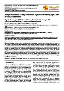
Fig. 1: Block diagram of a general FIS.
FUZZY INFERENCE SYSTEM A general fuzzy inference system consists of four parts; the fuzzifier, rule base, inference engine and defuzzifier, as shown in Fig. 1. A crisp input is fuzzified by input membership function (MF) and processed by a fuzzy logic interpretation of a fuzzy rules. Then is followed by a defuzzification stage resulting in a crisp output [2].
performs the above operations using a two register stack. Once the two values have been pushed onto the stack, a minimum or a maximum operation may be performed as requested by the rule evaluator. The defuzzification procedure uses the center of gravity method. This is again a very heavily used solution because of its proved effectiveness. The outputs will be defuzzified using the following formula:
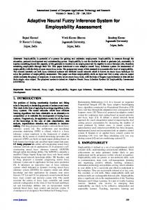
Fig. 2: Elements of a general FIS. FIS Design: The following steps are considered during the FIS design and implementation process[2]: - Define the control objectives and criteria. - Determine the input and output relationships. - Choose a minimum number of variables for FIS inputs and outputs. - Define a series of IF THEN rules to create the rulebased structure of the FIS. - Create fuzzy membership functions that define the meaning of Input/Output terms used in the rules. - Create the necessary fuzzy logic routines if implementing in software, otherwise program the rules into the fuzzy logic hardware engine. - Test the system, evaluate the results, tune the rules and membership functions, and retest until satisfactory results are obtained. As an example, the proposed FIS has two-input, single-output structure with 8-bit resolution. The inference engine implements Mamdani's min-max relation[2]. The defuzzification uses the center of gravity method. The membership functions as well as the fuzzy rules are stored in an EPROM Figure 2 illustrates all elements required to implement the proposed FIS. When new fire strength is required, it fetches that value by invoking the fire strength calculator. The rule evaluator requests fire strength by supplying a pointer to the required input and an address to the required membership of that input. The fire strength calculator uses these pointers as well as the value of the input to address a table in the EPROM that contains all the membership functions. The result is then presented to the min/max evaluator which performs the evaluation of the logic in the rule predicate. The single precision summer adds each of the results into an accumulator that will be used later as the denominator for the division. The multiplier multiplies the result of the rule evaluation by a coefficient, fetched from the EPROM, representing the weight of the output of the rule. The multiplied result is then accumulated in a double precision accumulator. Once all the rules have been evaluated, the defuzzification process begins. The value in the double precision accumulator is divided by the value in the single precision accumulator and the result is sent to the output. The min/max evaluator
∑ output =
n i =1
resulti * weighti
∑
n i =1
resulti
where; resulti: represents the ith result of the rule evaluation, and weighti: represents the corresponding weighting coefficient.
FIS IMPLEMENTATION Implementation is done using the Integrated Software Environment (ISE™) in the Xilinx® design software suite that allows you to take your design from design entry through Xilinx device programming. Field programmable gate arrays comprise an array of uncommitted circuit elements and interconnect resources. FPGA configuration is performed through programming by the end user.
Fig. 3: Phases of the implementation process. As illustrated in Fig. 3, the design of FPGAbased systems is composed of four phases; - Design entry phase: code in a Verilog (used in our case), or HDL, or by a schematic representation of the desired function. - Synthesis phase: done automatically by the design tools, during which the constraints and pin assignments are specified. - Implementation phase: includes the translation, mapping and placing & routing. - Code generation phase: the device programming can be accomplished.
Fig. 4: The top module schematic for the FIS.
FIS Modules: Figure 4 shows the top module schematic for the implemented FIS. It consists of these modules; - Input registers module. - Memory module. - Rule evaluator module. - Fire strength calculator modu.e. : - Min/Max evaluator module. - Multiplier module. - Summer module. - Double summer module. - Divider module. Several control signals are required to synchronize the operation of these modules according to the implemented algorithm. The fuzzy rules and membership functions are stored in the memory module. The format of the membership functions sets stored in memory (EPROM32X21M) is as follows: & & & The fuzzy rules are encoded in memory (EPROM64X22R) using the format: IF is is THEN is
Table 1 lists the general specification of the FIS, which has been realised on the Xilinx Spartan-3 FPGA board[13]. The general characteristics, and the macro statistics of this board are given in table 2 and table 3 respectively. This implementation uses only 49% of the available slices, 46% of the available lookup tables (LUTs) and 12% of input-output blocks (IOBs), see table 4. The average connection delay for this design is about 1.0 ns, the maximum pin delay is: 5.2 ns, then the maximum operating frequency is 78 MHz, and the total memory usage is 154 MB.
Table 1: FIS specifications. Max. number of inputs Max. number of outputs Membership functions number Max. number of rules Membership functions shape Resolution Defuzzification
up to 4 up to 4 up to 8 64 all forms 8-bit center of gravity
Table 2: Device Characteristics Device: Xilinx Spartan-3 XC3S200FT256 Slices: 3584, 256-ball thin Ball Grid Array System Logic Multipliers Clock Max I/O gates cells blocks (18*18) Managers Signals 200 k 4320 12 4 173 In-system Fast Select RAM PROM Asynchronous SRAM 18K-bits RAM Blocks K-bits 12 216 2 M-bits 1 M-byte
Table 3: Macro Statistics LUT RAMs ROMs Registers Counters Multiplexers Accumulators Latches Comparators Multipliers Adders/Subtractors
2x8-bit dual-port 7 ROMs, 16x4-bit each 55 2 3 2 8 7 32x8-bit 89
Table 4: Utilization Summary Item Slices Slice Flip Flops 4 input LUTs Bonded IOBs
Available 3584 7168 7168 173
Used 1787 85 3303 22
Percentage 49% 1% 46% 12%
FIS Operation: When the rule evaluator is first triggered by the Start signal, it checks the input registers. If they are ready, the evaluation begins by starting to retrieve the rules from the memory one by one in order. Each rule is then decoded and ready to be executed. Execution of a rule first begins by sending the membership address to the membership memory (EPROM32X21M), which in turn sends the membership function to the fire strength calculator module. The calculator computes the fire strength of each input of that rule and sends it to the Min/Max evaluator with a control signal sent to the rule evaluator indicating the fire strength is calculated and ready. The weight of the output of each rule is also computed and presented to the multiplier directly. The rule evaluator then sends a control signal to the Min/Max evaluator, after each rule is evaluated, so that the operation (AND/OR) of the rule takes place. The resulting fire strength of the evaluator is presented to both the multiplier and the summer. Then a control signal indicating the end of the operation evaluation is generated. The calculation of the center of gravity equation requires the calculation of the dividend, which is the sum of products of the resulting fire strength and the calculated weight of the output of each rule. This is done by using a multiplier and a double precision summer. The divisor is the sum of the resulting fire strengths. Then the final crisp value is produced from the divider.
FPGA-BASED WASHING MACHINE CONTROLLER Real-time systems have to respond to events occurring at irregular intervals. These events cause the system to move to a different state. In this case, state machine diagrams are used to model the behavior of real-time systems in response to internal or external events. State machine models are a good way of representing the design of a real-time system. Figure 5 shows a state machine model of a simple washing machine controlled by a fuzzy algorithm embedded in the FPGA. In fact, real washing machine state models are more complex than the given diagram. The operation state, for example, can be expanded as illustrated in Fig. 5. All hardware functions and software tasks are implemented by the FPGA. According to the washing machine state diagram, the FPGA will perform the following tasks: - read the user input commands. - measure motor rotating speed. - compute the required actuating signal applied to the PM motor. - generate the required control and monitoring signals.
Fig. 5: State machine model of a washing machine.
PM motor control The washing machine control task requires high torque at low speeds and low torque at high speeds, as illustrated in Fig. 6. High amount of torque is required to perform the washing cycle. Higher spinning speeds lead to greater centrifugal force resulting in better water extraction, shorter spinning cycles, and shorter drying times. During the wash cycle, the PM motor operates in slow speed region. The motor starts accelerating to a low speed level, then there is a certain time interval of steady spin and this is followed by the deceleration back to zero speed[11]. Upon completion of this positive operation sequence, the negative one is followed employing the same speed profile but with targeting the negative speed level.These operations alternate during wash cycle and the chosen wash program determines the overall time period of the wash cycle. The washing machine operation in spin-dry cycle starts by accelerating to a pre-defined high speed level for a short time. Then decelerating speed down either to stop or to proceed to a low speed level. This cycle might be repeated several times depending on a chosen wash program.
Fig. 6: Speed-torque characteristic of direct drive washing machines.
Fig. 7: FPGA-based PM Motor drive system. In order to run the PM motor efficiently, it is important to synchronize the frequency of the applied voltage to the rotor position of the PM rotor. An efficient control scheme is required to run the PM motor in sensorless drive. In this case, a fuzzy controller is proposed to satisfy the washing and drying cycles of the washing machine. Drive circuit elements The motor-drive circuit must detect the rotor position to synchronize the stator current with the rotor field. Given the rotor position, it is possible to drive the PM motor efficiently because the drive circuit can align the stator current to the optimum angle relative to the rotor field[11]. The PM motor is generally driven by a 3-phase PWM inverter which converts a constant voltage to 3-phase voltages corresponding to the rotor position. The hardware schematic for real-time implementation of the direct drive system is shown in Fig. 7, it consists; - PM motor, with 8-pole rotor. - Rotor position detector, producing 24 pulses each revolution. - Speed measurement to provide online measurement of rotating shaft. - PWM inverter. The motor speed can be measured either by calculating the rotor position pulses during a fixed period, or by calculating the time between each consecutive pulses coming from the rotor position sensor. In this application, the second approach is used. The rotor position is sampled 24 times per revolution, and each pulse causes a request to the FPGA. The real-time response of the speed measurement and fuzzy control tasks becomes critical at high speed (1500rpm), at which the sampling interval is only 1.667 msec, The PWM inverter has two control signals; the motor voltage, and the motor frequency. These two signals are arranged to be independent control inputs into the inverter, so that each input can be adjusted without affecting the other. The FIS calculates the duty cycle timing of the power switches to control the sinusoidal voltage applied to each phase of the motor.
Fig. 8: Motor speed response using fuzzy controller.
SIMULATION RESULTS The embedded fuzzy controller has been tested with the PM motor running a real-time mode. In this section, the simulation of the propose fuzzy controller, which is embedded in the FPGA, is applied to a PM motor. The obtained results demonstrate that such a controller is able to drive the motor accurately for a wide range of operation. The operation of the PM motor drive system has been tested for step input. Figure 8 shows the control action generated from the FPGA and speed response of the motor during acceleration and deceleration. The performance of the fuzzy controller can be improved by adaptively tuning a subset of its parameters such as number of membership functions and their shape. The obtained results demonstrate that the proposed fuzzy controller is quit enough for the washing machine control requirements. Figures 9 and 10 show the actuating signal and speed response for both washing and drying cycles. It is clear that such algorithm has a good tracking to input speed commands, and match the functionality of the washing machine. The obtained results demonstrate that such a controller is able to drive the motor accurately for a wide range of operation.
Fig. 9: Motor speed response during washing cycle.
[6].
Fig. 10: Motor speed response during drying cycle.
CONCLUSION Fuzzy controllers have been shown to be very promising in controlling ill-defined and complicated systems. The design and implementation of an FPGAbased washing machine control is presented in this paper. A typical fuzzy inference system, embedded on FPGA, has been used to control a PM motor. Also, the FPGA has been used for many computational and control tasks in a washing machine. It has been demonstrated that FPGAs are good computing devices which can be used to implement hardware functions and software tasks. Such implementation is suitable for the given application for these reasons: - Lead to shorter time-to-market for designs. - Reduce board size and cost. - Flexibility to adapt the hardware to changing application needs. - Provide high performance algorithms and functions for real-time applications. - Ease of usage.
REFERENCES [1]. Wang, L. X., 1994. Adaptive fuzzy systems and control: design and stability analysis. Prentice Hall Intr. Inc, NJ. [2]. Negnevitsky, M.,2005. Artificial intelligence; a guide to intelligent systems. Addison Wesley, USA. [3]. Ciletti M. D., 2002. Advanced digital design with the Verilog HDL. Prentice Hall, USA. [4]. Graham, P. and Nelson, B, 1998. FPGA-Based Sonar Processing. Available online on: http//www.splish.ee.byu.edu/docs/fpga98.beam.pdf.
[5]. Muresan, V., Crisu, D. and Wang, X, 1997. From VHDL to FPGA: a case study of a fuzzy logic controller. Proceedings of the Intr. Conf. of Young Lecturers and PhD Students, 11-17 August, Hungary, pp:11-17.
Welch, J. T. and Carletta, J., 2000. A direct mapping FPGA architecture for industrial process control applications. Proceeding of the 2000 IEEE Intr. Conf. on Computer Design: VLSI in Computers & Processors, ICCD2000. [7]. Kird M. and Masmoudi D., 2005. FPGA implementation of a feedforward neural network. 3rd Intr. Conf. on systems, signals & devices, SSD05, 21-24 March, Tunisia, pp: 1-6. [8]. Mehta, T. A., and Rotem J., 2005. FPGA coprocessing solutions for signal processing applications. ECE Journal, February, pp:26-27. [9]. Djemal, R., Demigny D., and Tourki, R. 2005. A real-time image processing with a compact FPGA-based architecture. Journal of computer science, 1 (2): 207-214. [10]. Murray A., 2006. Sensorless Motor Control Simplifies Washer Drives. Power Electronics Technology Magazine, June, pp:14-21. [11]. Al-Aubidy, K. M., and Ali, M. M., 2007. NeuroFuzzy controller for a Sensorless PM motor drive for washing machines. 4th Intr. Conf. on systems, signals & devices, SSD05, 21-24 March, Tunisia. [12]. Erenay K, Ciprut I, Tezduyar, & Istefanopulos, 1998. Application of fuzzy algorithms to the speed control of washing machines with brushless DC motors. Proceedings of International Conference on Electric Machines, Istanbul, Turkey, pp:1231-1236. [13]. Digilentic Co, 2004. Spartan-3 starter kit board user guide, Digilentic Co., Available online on: www.digilentinc.com.