Journal of Mechanical Science and Technology 28 (10) (2014) 4247~4256 www.springerlink.com/content/1738-494x
DOI 10.1007/s12206-014-0938-0
Multi-output fuzzy inference system for modeling cutting temperature and tool life in face milling† Pavel Kovac*, Dragan Rodic, Vladimir Pucovsky, Borislav Savkovic and Marin Gostimirovic Department of Production Engineering, Faculty of Technical Science, University of Novi Sad, Trg Dositeja Obradovica 6, 21000 Novi Sad, Serbia (Manuscript Received September 16, 2013; Revised April 14, 2014; Accepted June 13, 2014) ----------------------------------------------------------------------------------------------------------------------------------------------------------------------------------------------------------------------------------------------------------------------------------------------
Abstract This paper proposes a method for cutting parameters identification using the multi-inputs-multi-outputs fuzzy inference system (MIMO-FIS). The fuzzy inference system (FIS) was used to identify the initial values for cutting parameters (cutting speed, feed rate and depth of cut) and flank wear using cutting temperature and tool life as outputs. The objective was to determine the influence of cutting parameters on cutting temperature and tool life. The model for determining the cutting temperature and tool life of steel AISI 1060 was trained (design rules) and tested by using the experimental data. The average deviation of the testing data for tool life was 11.6 %, while that of the cutting temperature was 3.28 %. The parameters used in these testing data were different from the data collected for the design rules. The test results showed that the proposed MIMO-FIS model can be used successfully for machinability data selection. The effect of parameters and their interactions in machining is analyzed in detail and presented in this study. Keywords: Fuzzy logic; Mamdani FIS; Face milling; Cutting temperature; Tool life ----------------------------------------------------------------------------------------------------------------------------------------------------------------------------------------------------------------------------------------------------------------------------------------------
1. Introduction Metal cutting is a very common type of machining in manufacturing, as industries strive to achieve either a minimum cost of production or a maximum production rate, or an optimum combination of both, along with better product quality in machining [1]. A significant improvement in process efficiency may be obtained by process parameter optimization. It is required to undertake parameter optimization within the metal cutting process in the two following stages: (i) modeling of input-output and in-process parameter relationship, and (ii) determination of optimal or near-optimal cutting conditions [2]. Process parameter modeling of any manufacturing process is usually a difficult task. The modeling techniques of inputoutput and in-process parameter relationships are mainly based on statistical regression, fuzzy set theory, and artificial neural networks [3]. This paper focuses on an approach using fuzzy set theory to establish tool wear reference models for prediction of cutting temperature and tool life in face milling, without the application of cooling and lubricating agents. Cutting temperature and tool life in the metal cutting process are very important factors affecting production optimization. The importance of temperature prediction for the machining processes has been well recognized in the machining *
Corresponding author. Tel.: +381 21 485 2329, Fax.: +381 21 454 495 E-mail address:
[email protected] Recommended by Associate Editor In-Ha Sung © KSME & Springer 2014 †
research community primarily due to its effects on tool wear and its constraints on productivity [4]. Tool life can be defined in terms of the progressive wear occurring on the tool rake face (crater wear) and/or clearance face (flank wear). Of these two, flank wear is often used to define the end of effective tool life [5]. Wear at the rake face is known as crater wear and results in tool breakage, but it does not affect the surface finish and dimensional accuracy of the workpiece. Flank wear takes place due to the friction between the tool flank and the freshly generated workpiece surface and adversely affects the tool life as well as dimensional accuracy and surface finish of the workpiece, thus resulting in material loss [6]. Different analytical methods are developed and used for predicting tool life and cutting temperature [7, 8]. Alauddinel et al. [9] presented the development of mathematical models for tool life in end milling steel using high-speed steel slot drills under dry conditions. Wanigarathne et al. [10] examined the cutting tool-wear progression through an experimental study focusing on cutting temperatures and progressive tool wear. Lajis et al. [11] developed a mathematical model to predict tool life for end milling of hardened steel. Other typical works by analytical methods are those reported in Refs. [12, 13]. Unfortunately, most analytical studies thus far have focused on thermal modeling only for fresh tools. One of the important aims of this paper is to examine the influence of flank wear on cutting temperature and tool life in face milling. Fuzzy logic (FL) is used for describing the relationship be-
4248
P. Kovac et al. / Journal of Mechanical Science and Technology 28 (10) (2014) 4247~4256
tween system inputs and outputs. It is widely used to develop rule-based expert systems in complex process modeling that are difficult to be modeled analytically under various assumptions [14, 15]. There have been many successful applications of fuzzy set theory in metal machining. Yao et al. [16] present a new tool wear estimation method by application of a wavelet fuzzy neural network in which the acoustic emission and motor current signal are utilized to extract effective features. Susanto and Chen [17] developed and presented a fuzzy logic based in-process tool-wear monitoring. The fuzzy membership function and rule bank were based on observations during cutting experiments using artificial tool-wear inserts in face milling operations. Balazinski and Jemielniak [18] introduced a fuzzy decision support system for estimating the depth of cut and flank wear during the turning process. Quiza et al. [19] carried out an experimental investigation on tool wear prediction on ceramic cutting tools used for turning hardened cold rolled tool steel. They predicted tool wear with the help of neural network and regression models. Simranpreet [20] proposed to model the flank wear of cryogenically treated AISI M2 high speed steel by means of the ANFIS approach. It combined the modeling function of fuzzy inference with the learning ability of artificial neural network, thus generating a set of rules directly from experimental data. Tanikic et al. [21] presented the application of artificial neural networks and a hybrid, neuro-fuzzy model in the prediction of a workpiece temperature and surface roughness. Aydin et al. [22] presented an approach for modeling and prediction of both surface roughness and cutting zone temperature in turning of austenitic stainless steel using multi-layer coated tungsten carbide tools. All of the above-mentioned models were developed with a single output. The MISO (multi-inputs-single-output) fuzzy systems configured in literature are very general and may be considered as universal approximators. The second contribution of this paper includes the development of a fuzzy model with multi-input-multi-output (MIMO) FIS model. The fuzzy inference system (FIS) model was used to identify the initial values for cutting parameters (cutting speed, feed rate, depth of cut and flank wear) using cutting temperature and tool life as outputs. The effect of such parameters and their interactions in machining is analyzed in detail and presented in this study. To date, there has been no study on MIMO FIS modeling for cutting temperature and toll life prediction that combines cutting conditions in face milling (cutting speed, feed rate and depth of cut) and flank wear value. The effect of various parameters on cutting temperature and tool life was researched in literature, but there is an absence of tool wear parameters and their influence on cutting temperature tool life. It is considered that tool wear has very high influence on cutting temperature. The present paper also dissects the concept of tool wear within a study of cutting temperature and tool life function modeling. Similarly to the majority of presented approaches, this model connects the elements of cutting parameters. The paper at hand develops a model for
Table 1. The chemical composition of steel AISI 1060. Components
Percent [%]
C
0.61
Si
0.22
Mn
0.72
S
0.029
P
0.014
Table 2. The tool geometry parameters. Tool geometry parameters
Value
Tool normal rake [º]
7
Tool normal clearance [º]
18
Tool cutting edge angle [º]
75
the identification of cutting parameters using multi-inputsmultiple-outputs fuzzy inference system (MIMO-FIS). As an addition to the proposed model, tool wear is also included because it represents an influential parameter in cutting temperature and tool life modeling. Including the concept of wear into the model requires a much longer and more expensive experimental study, since it has to monitor wear until the end of tool life.
2. Experimental procedures and material The experiments were carried out on steel AISI 1060 in normalized condition. The chemical components of which are shown in Table 1. The working material was a block of 100 x 120 x 600 mm of steel AISI 1060 and was fixed on milling machine table. The single tooth face milling cutter of 125 mm diameter, with plates of hard metal SPAN 12 03 ER, quality P25 was used as tool. Geometrical elements of the tool cutting part did not vary, its geometrical parameters being displayed in Table 2. In planning and conducting the experiment, four factorial 2k central compositional experimental plans were used. Selected factors of experiment have changed in five levels of value. This method allows investigating the wider interval of parameters and predicted mathematical model is more reliable. The experiment was carried out for different combinations of cutting speed (v) [m / s], feed per tooth (ft) [mm / t], or the appropriate machines speed [mm / min], cutting depth (a) [mm], flank wear land (VB) [mm] according to the planning of experiment (Tables 3 and 4). The investigations were carried out on the vertical milling machine, with driving power of 14 kW. All the investigations were without the application of cooling and lubricating agents. The measurement of wear size on face surface of tool was performed on Zeiss digital measure microscope. The measurement of temperature change on flank surface was performed by a standard thermocouple Cr-Ni. From turning spindle of milling machine signal transmitting is made by slip
4249
P. Kovac et al. / Journal of Mechanical Science and Technology 28 (10) (2014) 4247~4256
Table 3. Machining parameters and their levels. Levels (membership functions)
Cutting speed (m/s)
Feed (mm/tooth)
Depth of cut (mm)
Flank wear VB (mm)
Highest
4.65
0.351
3.37
0.40
High
3.67
0.280
2.25
0.28
Medium
2.95
0.223
1.5
0.18
Low
2.32
0.178
1.0
0.12
Lowest
1.83
0.142
0.67
0.08
Table 4. Experimental data for defining rules. Tool life (min)
Cutting temperature (°C)
v (m/s)
ft (mm/tooth)
a (mm)
VB (mm)
Exp.
Fuzzy
Regr.
Exp.
Fuzzy
Regr.
1.
2.32
0.178
1
0.12
8
7.45
10.9
79
96.11
83.9
2.
3.67
0.178
1
0.12
6
7.15
4.4
106
104.2
103.2
3.
2.32
0.280
1
0.12
9
8.70
7.2
92
87.8
95
4.
3.67
0.280
1
0.12
2
2.05
2.9
112
116.4
116.8
5.
3.67
0.178
2.25
0.12
5.2
5.06
4.4
130
129
146.6
6.
3.67
0.280
2.25
0.12
5.16
5.55
2.9
173
168
165.9
7.
2.32
0.178
1
0.28
42
42.4
40.2
102
103.1
99.2
8.
2.32
0.280
1
0.28
30
29.6
26.7
104
103.2
112.2
9.
2.32
0.178
2.25
0.28
43.5
42.4
40.2
150
147.4
140.8
10.
3.67
0.280
1
0.28
9.2
8.65
10.7
147
146.9
138
11.
3.67
0.178
2.25
0.28
18.5
19
16.1
161
162
173.2
12.
2.32
0.280
2.25
0.28
32
29.6
26.7
148
147
159.4
13.
3.67
0.280
2.25
0.28
6.5
6.37
10.7
182
178.6
196
14.
1.83
0.223
1.5
0.18
20
20.4
26.7
117
119.7
103.5
15.
4.65
0.223
1.5
0.18
3.2
3.71
4.1
167
159.6
157.7
16.
2.95
0.351
1.5
0.18
7
6.61
6.8
157
161
145.3
17.
2.95
0.223
0.67
0.18
14
14.5
10.3
88
91.1
90.6
18.
2.95
0.223
3.37
0.18
13
13.6
10.3
205
199.8
182.2
19.
2.95
0.223
1.5
0.08
2
2.29
2.9
118
115.71
109.4
20.
2.95
0.142
1.5
0.18
13
14.5
10.3
115
120.71
113.5
No.
AVERAGE ERROR Tool life: Fuzzy = 5.78%; Regression = 24.87% Cutting temperature: Fuzzy = 3.04%; Regression = 6.37%
rings. Reading of temperature quality was done digitally on the "digital thermometer" - TR 2112 instrument equipped with automatic regulation of cold junction temperature.
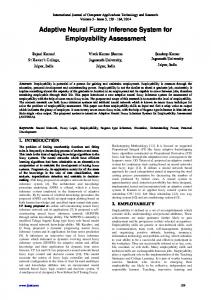
3. Fuzzy modeling The process of fuzzy inference involves membership functions, fuzzy logic operators, and if-then rules. The basic structure of an FIS consists of three conceptual components: a rule base containing a selection of fuzzy rules; a database defining the membership functions (MF) used in the fuzzy rules; and a reasoning mechanism performing the inference procedure upon the rules to derive an output. The parameters of the ifthen rules (referred to as antecedents or premises in fuzzy modeling) define a fuzzy region of the input space, while the output parameters (also used as consequents in fuzzy model-
ing) specify the corresponding output (Fig. 1). Two types of FIS’s, the Mamdani FIS and the Sugeno FIS, have been widely used in various applications [23, 24]. These types of inference systems vary somewhat in the way outputs are determined. Based on the survey done, it can be observed that the Mamdani FIS is intuitive and its rule base can be easily interpreted. However, in the Sugeno FIS, the consequents of the rules are not fuzzy. Hence, the power of interpretation is lost. However, consequents of the Sugeno rules can have the same number of parameters in their consequent per rule as the number of input values. This offers more flexibility to the Sugeno FIS over the Mamdani FIS. On the other hand, the Mamdani FIS can be used directly for both multi-input-singleoutput (MISO) systems and multi-input-multiple-output (MIMO) systems. In terms of use, the Mamdani FIS is more widely used, mostly because it provides reasonable results
4250
P. Kovac et al. / Journal of Mechanical Science and Technology 28 (10) (2014) 4247~4256
Fig. 1. Fuzzy inference system.
with a relatively simple structure, and also due to the intuitive and interpretable nature of the rule base. Since the consequents of the rules in a Sugeno FIS are not fuzzy, its interpretability is lost; however, owing to the fact that the consequents of the Sugeno FIS can have as many parameters per rule as input values, this translates into more degrees of freedom in the design than a Mamdani FIS, thus providing the system’s designer with more flexibility when constructing the system [25]. In this paper, the Mamdani FIS model is used to calculate the tool life and cutting temperature. Mamdani FIS is the most known or used in developing fuzzy models. The output of the system is generally defuzzified. Resulting fuzzy sets are combined using aggregation operator from the consequent of each rule of the input. Fuzzy knowledge base systems can be formed on the basis of expert knowledge or automatic generation of rules based on previously measured data. Irrespective of the manner of formation, the knowledge base has generally the same form. In a system with one input and one output, the knowledge base R contains n rules in the following form: R = {R1 , R2 ,... , Rn }
(1)
where each nth rule has the following form: IF
(2)
X is A THEN Y is B
or in a mathematical form:
{ IF ( premise )THEN ( consequent ) } i
i
n i =1
(3)
where A and B are linguistic values defined by fuzzy sets on the ranges X and Y, respectively. The if-part of the rule “X is A” is called the antecedent or premise, while the then-part of the rule “Y is B” is called the consequent or conclusion. The input to an if-then rule is the current value for the input variable and the output is generally defuzzified. Resulting fuzzy sets are combined using aggregation operator from the consequent of each rule of input. Depending on the system, it may not be necessary to evaluate every possible input combination since some may rarely, or never occur. By making this type of evaluation which is usually done by an experienced operator, fewer rules can be evaluated, thus simplifying the processing logic and perhaps even improving the fuzzy logic system per-
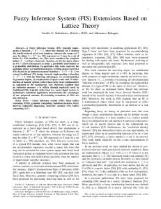
formance [26]. The design of a fuzzy logic system is divided into three phases. The first is to define a fuzzy variable, followed by forming the set of all fuzzy subsets of variables with the appropriate membership functions. In the third phase fuzzy rules are formed. In this experiment, the input variables considered are cutting speed, feed rate, depth of cut and flank wear land. The output variables are tool life (T) and cutting temperature (θ). The majority of research performed in this field discovered a unique relationship between cutting temperature and tool life [27, 28]. As conclusively proven by Makarow [29], the temperature is the most suitable parameter to correlate the tribological conditions at the discussed interfaces with tool wear. Therefore, a correlation of the cutting temperature with parameters of the cutting system should be established. In this work, an attempt has been made to develop a fuzzy inference system (FIS) model for the prediction of cutting temperature and tool life in the face milling process using an integrated multi-input multi-output (MIMO) FIS. The elementary stage in fuzzy logic is the selection of appropriate shapes of the membership function for developing an algorithm in order to select the machining parameters. The membership function is a graphical representation of the magnitude of participation of each parameter. It associates a weighting with each of the inputs that are processed, defines the functional overlap between inputs, and ultimately determines an output response. For the prediction of output parameters such as cutting temperature and tool life, the face milling process is modeled using four input parameters such as cutting speed, feed rate, depth of cut and flank wear land. The fuzzy expressions for different input parameters are shown in Table 3. For example (Fig. 2(a)), the fuzzy sets of cutting speed are (Lowest, Low, Medium, High and Highest), the degree of membership is equal to 1, the corresponding current will be (1.83 m/s; 2.32 m/s; 2.95 m/s; 3.67 m/s; 4.65 m/s), the cutting speed values will be used in experiments. In this way, the feed rate is (0.142; 0.178; 0.223; 0.280; 0.351) (Fig. 2(b)), the depth of cut is (0.67; 1; 1.5; 2.25; 3.37) (Fig. 2(c)), and the flank wear is (0.08 mm; 0.12 mm; 0.18 mm; 0.28 mm; 0.4 mm) (Fig. 2(d)) for the experiments. Each experiment will result in certain output parameters that are to be classified into the corresponding fuzzy set of output variable. The number of membership functions used for the first output response is nine, i.e., A, B, C, D, E, F, G, H, I, while the second output is eight: A, B, C, D, E, F, G, H. More precise results can be obtained by using a greater number of membership functions. Hence, nine and eight membership functions were selected for the present work. Each fuzzy set is defined by a separate membership function. The output response of the fuzzy processes can only be viewed in fuzzy values that have to be defuzzified. The membership functions used for the output response tool life and temperature are presented in Figs. 2(e) and 2(f). Fuzzy logic uses membership functions representing an ar-
P. Kovac et al. / Journal of Mechanical Science and Technology 28 (10) (2014) 4247~4256
4251
Fig. 2. (a) Membership functions for cutting speed; (b) membership functions for feed rate; (c) membership functions for depth of cut; (d) membership functions for flank wear; (e) membership functions for tool life; (f) membership functions for cutting temperature.
bitrary curve. Although there are many numbers of membership functions available, such as triangular, trapezoidal, Gaussian, etc., in this paper we used the Gaussian type for tool life and cutting temperature modeling. The symmetric Gaussian function depends on two parameters, where σ and c are given: -( x -c)
f ( x;s , c ) = e
2s 2
(4)
where c is the mean value (center), and σ is the standard deviation (width of the ‘base’ curve). The concept of fuzzy reasoning for a four-input and twooutput fuzzy logic unit is described as follows: The fuzzy rule base consists of a group of IF- THEN statements with four inputs: x1 (cutting speed), x2 (feed), x3 (depth of cut) and x4 (flank wear) and two outputs: y1 (tool life) and y2 (cutting temperature). Thus the general form of rule base systems with multiple inputs and multiple outputs is: Input : x1 is Ai and x2 is Bi and x3 is Ci and x4 is Di ______________________________________________________ R1 : x1 is A1 and x2 is B1 and x3 is C1 and x4 is D1 THEN y1 is E1 and y2 is F1 R2 : x1 is A2 and x2 is B2 and x3 is C2 and x4 is D2 THEN y1 is E2 and y2 is F2 M Ri : x1 is Ai and x2 is Bi and x3 is Ci and x4 is Di THEN y1 is Ei and y2 is Fi ______________________________________________________ Output : y1 is E ' and y2 is F '
(5)
where x1, x2, x3 and x4 are variables describing the process status and representing the input size of a fuzzy system, while y1, y2 are the outputs of a fuzzy system. Ai, Bi, Ci, Di and Ei are linguistic values defined by fuzzy sets on the ranges, x1, x2, x3, x4 and y1, y2 respectively. After that the implication function modifies the fuzzy set to a degree specified by the antecedent. The most common way to modify the output fuzzy set is truncation using the MIN function. Each rule from the previous set of rules can be viewed as a fuzzy implication, so that the ith rule can be defined as: m Ri = m( Ai Ù Bi Ù Ci Ù Di Þ Ei ) ( x1 , x2 , x3 , x4 , y1 , y2 ) = = éë m Ai ( x1 ) Ù m Bi ( x2 ) Ù mCi ( x3 ) Ù m Di ( x4 ) ùû Þ
(6)
Þ m Ei ( y1 ) Ù m Fi ( y 2 ) .
We used the Mamdani MIN implication operator, whereby the implication operator takes as an input the membership function of an antecedent µAi(x1)^µBi(x2)^µCi(x3)^µDi(x4), while µEi(y1)^µFi(y2) is consequent. Every rule has a weight (number between 0 and 1) which is applied to the number given by the antecedent. Finally, a defuzzification method is used to transform the fuzzy output into a non-fuzzy value y0. Defuzzification is carried out by using the centroid defuzzification method. It produces the center area of the possibility distribution of the inference output. It is also one of the most frequently used de-
4252
P. Kovac et al. / Journal of Mechanical Science and Technology 28 (10) (2014) 4247~4256
Table 5. Set of rules for MIMO model (rule bank). No.
v (m/s)
ft (mm/tooth)
a (mm)
VB (mm)
Tool life (min) Exp. value
Tool life (min) fuzzy value
Weight rules
1.
LOW
LOW
LOW
LOW
A
A
1
2.
HIGH
LOW
LOW
LOW
C
B
1
3.
LOW
HIGH
LOW
LOW
D
A
1
4.
HIGH
HIGH
LOW
LOW
A
C
0.35
5.
HIGH
LOW
HIGH
LOW
B
D
0.5
6.
HIGH
HIGH
HIGH
LOW
C
H
0.04
7.
LOW
LOW
LOW
HIGH
I
B
1
8.
LOW
HIGH
LOW
HIGH
H
B
1
9.
LOW
LOW
HIGH
HIGH
D
E
1
10.
HIGH
HIGH
LOW
HIGH
I
E
1
11.
HIGH
LOW
HIGH
HIGH
G
F
1
12.
LOW
HIGH
HIGH
HIGH
H
E
1
13.
HIGH
HIGH
HIGH
HIGH
C
G
1
14.
LOWEST
MEDIUM
MEDIUM
MEDIUM
G
D
0.1
15.
HIGHEST
MEDIUM
MEDIUM
MEDIUM
A
F
0.07
16.
MEDIUM
HIGHEST
MEDIUM
MEDIUM
C
F
1
17.
MEDIUM
MEDIUM
LOWEST
MEDIUM
E
A
0.001
18.
MEDIUM
MEDIUM
HIGHEST
MEDIUM
E
H
1
19.
MEDIUM
MEDIUM
MEDIUM
LOWEST
A
C
0.4
20.
MEDIUM
LOWEST
MEDIUM
MEDIUM
E
C
0.1
fuzzification methods using the centroid of the area under the membership function for calculation: n
n
åy m (y ) 1
y1, =
Ei
1
i =1 n
å m Ei ( y1 ) i =1
åy m (y ) 2
Ù
y2, =
Fi
2
i =1 n
,
(7)
å m Fi ( y2 ) i =1
4. Results and discussion To establish the effectiveness of the MIMO model, it is necessary to employ a theoretical model for prediction purposes by using conventional techniques (regression modeling) to modeling cutting temperature and tool life. These adequate regression models were obtained as follows: q = 324, 2620 × v -1.9999 × f -0.9004 × a 0.0011 × VB1.5394 , T = 139, 4950 × v 0.4515 × f 0.2726 × a 0.4326 × VB 0.1969 ,
where y1’ and y2’ = the defuzzified outputs (the output for a given input vector, which was the predicted by T and θ values in this study.); µEi and µFi = the aggregated membership functions; y1 and y2 = the output variables (the centre value of the regions). The rule bank for the system was based on experimental data. As mentioned by Khalaj et al. [30], human expertise was also required to obtain an optimum fuzzy result. Table 5 shows the rule bank for the MIMO model; IF-THEN logic was also employed in the inference element to determine the output. The non-fuzzy values y1 and y2 give the outputs cutting temperature and tool life values in numerical form. For example, the value of tool life and cutting temperature at a cutting condition, cutting speed of 2.32 m/s, feed of 0.178 mm/tooth, depth of cut of 1 mm and flank wear 0.12 mm are obtained as T = 7.45 min and θ = 96.1ºC, whereby the MATLAB fuzzy logic tool was used for the calculation.
(8) (9)
where θ - cutting temperature [°C], T - tool life [min], v - cutting speed in m/s, f - feed per mm/tooth, a - depth of cut in mm and VB - flank wear land in mm. Comparative observation showed that the MIMO model gives a slightly smaller deviation of the measured model values than the regression method. Table 4 shows the compared values obtained by the experiment, and estimated by the models of fuzzy logic and regression analysis. The average deviation of the fuzzy model for cutting temperature is 3.04% and tool life is 5.78%; while the average deviation of the regression model for cutting temperature is 6.37% and tool life is 24.87%. Research showed that the fuzzy logic model gives a more accurate prediction of cutting temperature and tool life. Two different sets of data patterns are prepared for MIMO FIS development; one set is comprised of 20 patterns (75% of total patterns) for designing fuzzy rules, while the second set
4253
P. Kovac et al. / Journal of Mechanical Science and Technology 28 (10) (2014) 4247~4256
Table 6. Validation data for MIMO - FIS. No.
Tool life (min)
v ft a VB (m/s) (mm/tooth) (mm) (mm)
Cutting temperature (°C)
Exp.
Fuzzy
Exp.
Fuzzy
1. 2.32
0.178
2.25 0.12
8
8.55
115
119.5
2. 2.32
0.280
2.25 0.12
7
7.06
125
132
3. 3.67
0.178
1
0.28
16.6
13.7
126
126
4. 2.95
0.223
1.5
0.18
13.3
15.7
128
121
5. 2.95
0.223
1.5
0.40
28
24.5
150
147.7
Tool life: Fuzzy = 11.6%
AVERAGE ERROR Cutting temperature: Fuzzy = 3.28%
(a)
(b)
Fig. 3. Comparison of predicted results with actual values for: (a) tool life; (b) cutting temperature.
is comprised of 5 patterns (25% of total patterns) for design testing. The parameters used in these testing data were different from the data collected for the experiment. The testing data are presented in Table 6. Results obtained by means of the Mamdani fuzzy system of reasoning, using rules that are defined on the basis of experimental data, show corresponding results with experiment. This shows that the selected types of membership functions (gaussmf) type reasoning mechanism by the method of MIN PROD and selected defuzzification centroid method (center of gravity) are a good choice. The average deviation of the testing data for cutting temperature is 3.28 % and tool life is 11.6 % (Table 6). Fig. 3 illustrates the comparison of experimental and fuzzy test results for the tool life and cutting temperature, respectively. It proves that the method used in this paper is feasible and could be used to predict the θ and T in an acceptable error rate for face milling. In Fig. 4 we plotted the main effects for cutting temperature and tool life. This figure displays the effect of machining parameters and their interaction on cutting temperature and tool life. The influence of feed rate on cutting temperature change is similar to the impact of cutting speed. The effect of cutting speed and feed rate on the cutting temperature is shown in Figs. 4(d) and 4(e). These figures display that the value of cutting temperature increases with the increase of cutting speed and feed rate. The most significant factor on the cutting temperature is the depth of cut. Clearly, the depth of cut
strongly affects cutting temperature parameters. The depth of cut has an increasing effect. On the other hand, from Fig. 4(f), higher depth of cut results in increased cutting temperature. Fig. 5(b) shows how cutting temperature is contributed from depth of cut for constant values of three other factors. The highest depth of cut of 3.37 mm has a maximum value of initial temperature. Any change in the cutting speed leads to a corresponding change in the cutting temperature, so that cutting speed should influence tool life. Cutting speed has a great influence on tool life (Fig. 4(a)). Cutting speed has an important and decreasing effect. The influence of feed rate on tool life is slightly lower than that of cutting speed (Fig. 4(b)). Depth of cut has the least influence on the wear on the flank surface (Fig. 4(c)). Tool life is improved by decreasing cutting speed. When cutting speed is at full 4.65 m/s, cutting temperature is high, which results in rapid tool wear and a short tool life of about a few minutes. Fig. 5(a) shows how tool life is contributed from cutting speed for constant values of 3 other factors (at a cutting speed of 4.65 m/s tool life seems even worse). Fig. 6 exhibits a three-dimensional surface profile obtained during fuzzy logic modeling for the following machining parameters: cutting speed, feed, depth of cut and flank wear on tool life and cutting temperature, where any two of the inputs vary, but two of the inputs must be held constant because computer monitors cannot display a five-dimensional shape. Fig. 6(b) shows results at a medium level of cutting speed and a high level depth of cut., i.e., that this has a high impact
4254
P. Kovac et al. / Journal of Mechanical Science and Technology 28 (10) (2014) 4247~4256
Fig. 4. (a) Influence cutting speed on tool life; (b) influence feed rate on tool life; (c) influence depth of cut on tool life; (d) influence cutting speed on cutting temperature; (e) influence feed rate on cutting temperature; (f) influence depth of cut on cutting temperature.
(a)
(b)
Fig. 5. Fuzzy results of: (a) tool life; (b) cutting temperature, in face milling process.
(a)
(b)
Fig. 6. Fuzzy surface of: (a) tool life; (b) Cutting temperature, in face milling process.
on cutting temperature. In Fig. 6(a), low cutting speed and low feed rate result in longer tool life.
5. Conclusion This paper suggests a fuzzy system for selecting the introduced face milling parameters. The fuzzy model was developed based on the face milling of correction steel AISI 1060. The adequacy of the model was checked and found to be adequate approximately at 90% confidence level and the model
can be used for predicting the cutting temperature and tool life in machining of AISI 1060. Experimental results showed that in machining of correction steel AISI 1060 the cutting temperature increased with an increase in depth of cut. In addition, tool life decreased with an increase in cutting speed. The remaining parameters have less influence on the cutting temperature and tool life. Comparison and validation of fuzzy results with experiment findings verified the high accuracy of models. The fuzzy modeling technique could be an economical and successful method for prediction of face milling output
P. Kovac et al. / Journal of Mechanical Science and Technology 28 (10) (2014) 4247~4256
parameters according to input variables.
Acknowledgment The paper is the result of the research within the project TR 35015 financed by the Ministry of Science and Technological Development of the Republic of Serbia.
Nomenclature-----------------------------------------------------------------------θ T a ft v VB
: Cutting temperature : Tool life : Depth of cut : Feed per tooth : Cutting speed : Width of flank wear land
References [1] R. V. Rao, Advanced modelling and optimization of manufacturing processes, Springer-Verlag, London (2011). [2] S. Markos, Z. J. Viharos and L. Monostori, Quality-oriented, comprehensive modelling of machining processes, Sixth ISMQC IMEKO symposium on metrology for quality control in production (1998) 67-74. [3] T. Rajmohana, K. Palanikumar and S. Prakashc, Grey-fuzzy algorithm to optimise machining parameters in drilling of hybrid metal matrix composites, Composites Part B: Engineering, 50 (2013) 297-308. [4] E. Usui, T. Shirakashi and T. Kitagawa, Analytical prediction of three dimensional cutting process, Part 3: Cutting temperature and crater wear of carbide tool, Journal of Manufacturing Science and Engineering, 100 (1978) 236-243. [5] F. Jafarian, M. Taghipour and H. Amirabadi, Application of artificial neural network and optimization algorithms for optimizing surface roughness, tool life and cutting forces in turning operation, Journal of Mechanical Science and Technology, 27 (2013) 1469-1477. [6] S. Khamel, N. Ouelaa and K. Bouacha, Analysis and prediction of tool wear, surface roughness and cutting forces in hard turning with CBN tool, Journal of Mechanical Science and Technology, 26 (2012) 3605-3616. [7] E. Usui, T. Shirakashi and T. Kitagawa, Analytical prediction of cutting tool wear, Wear, 100 (1984) 129-151. [8] T. Matsumura, T. Obikawa, T. Shirakashi and E. Usui, Autonomous turning operation planning with adaptive prediction of tool wear and surface roughness, Journal of Manufacturing Systems, 12 (1993) 253-262. [9] M. Alauddinel, M. A. Baradie and M. S. J. Hashmi, Prediction of tool life in end milling by response surface methodology, Journal of Materials Processing Technology, 71 (1997) 456-465. [10] P. C. Wanigarathne, A. D. Kardekar, O. W. Dillon, G. Poulachon and I. S. Jawahir, Progressive tool-wear in machining with coated grooved tools and its correlation with cutting
4255
temperature, Wear, 259 (2005) 1215-1224. [11] M. A. Lajis, K. A. N. Mustafizul, A. K. M. Nurul and L. G. T. Hafiz, Prediction of tool life in end milling of hardened steel AISI D2, European Journal of Scientific Research, 21 (2008) 592-602. [12] M. C. Shaw, Metal cutting principles, Clarendon Press, Oxford (1984). [13] Minis, R. Yanushevsky, A new theoretical approach for the prediction of machine tool chatter, ASME Journal of Engineering for Industry, 115 (1993) 1-8. [14] M. R. H. Adnan, A. Sarkheyli, A. M. Zain and H. Haron, Fuzzy logic for modeling machining process: a review, Artificial Intelligence Review (2013) doi: 10.1007/s10462-0129381-8. [15] Z. Jakovljevic, B. P. Petrovic, V. D. Mikovic and M. Pajic, Fuzzy inference mechanism for recognition of contact states in intelligent robotic assembly, Journal of Intelligent Manufacturing (2012) doi: 10.1007/s10845-012-0706-x. [16] YX Yao, XL Li and ZJ Yuan, Tool wear detection with fuzzy classification and wavelet fuzzy neural network, Int. J. Mach. Tool Manuf., 39 (1999) 1525-1538. [17] V. Susanto and J. C. Chen, Fuzzy logic based in- process tool-wear monitoring system in face milling operations, The International Journal of Advanced Manufacturing Technology, 21 (2003) 186-192. [18] M. Balazinski and K. Jemielniak, Tool condition monitoring using fuzzy decision support system, In: V CIRP, International conference on monitoring and automatic supervision in manufacturing (1998) 115-121. [19] R. Quiza, L. Figueira and J. P. Davim, Comparing statistical models and artificial neural networks on predicting the tool wear in hard machining D2 AISI steel, International Journal of Advanced Manufacturing Technology, 37 (2008) 641-648. [20] Simranpreet Singh Gill, Rupinder Singh, Jagdev Singh and Harpreet Singh, Adaptive neuro-fuzzy inference system modeling of cryogenically treated AISI M2 HSS turning tool for estimation of flank wear, Expert Systems with Applications, 39 (2012) 4171-4180. [21] D. Tanikic, M. Manic, G. Devedzic and Z. Stevic, Modelling Metal Cutting Parameters Using Intelligent Techniques, Journal of Mechanical Engineering, 56 (2010) 52-62. [22] M. Aydın, C. Karakuzu, M. Ucar, A. Cengiz and M. A. Cavuslu, Prediction of surface roughness and cutting zone temperature in dry turning processes of AISI304 stainless steel using ANFIS with PSO learning, International Journal of Advanced Manufacturing Technology, 64 (2012) 1045-1060. [23] A. Majumder. Process parameter optimization during EDM of AISI 316 LN stainless steel by using fuzzy based multiobjective PSO, Journal of Mechanical Science and Technology, 27 (2013) 2143-2151. [24] Chi-Yao Hsu, Sheng-Fuu Lin and Jyun-Wei, Chang Data mining-based hierarchical cooperative coevolutionary algorithm for TSK-type neuro-fuzzy networks design, Neural Computing and Applications (2012) doi: 10.1007/s00521-
4256
P. Kovac et al. / Journal of Mechanical Science and Technology 28 (10) (2014) 4247~4256
012-0943-0. [25] D. Tikk, L. T. Koczy and T. D. Gedeon, A survey on universal approximation and its limits in soft computing techniques, International Journal of Approximate Reasoning, 33 (2003) 185-202. [26] G. J. Klir and T. A. Folger, Fuzzy sets, uncertainty and information, Prentice-Hall of India Private Limited, New Delhi (1988). [27] B. N Colding, A tool-temperature/tool-life relationship covering a wide range of cutting data, CIRP Annals - Manufacturing Technology, 40 (1991) 35-40. [28] X. L. Liu, D. H. Wen, Z. J. Li, L. Xiao and F. G. Yan, Cutting temperature and tool wear of hard turning hardened bearing steel, Journal of Materials Processing Technology, 129 (2002) 200-206. [29] A. D. Makarow, Optimization of cutting processes, Mashinostroenie, Moscow (1976).
[30] Gholamreza Khalaj, Hossein Yoozbashizadeh, Alireza Khodabandeh and Ali Nazari, Modeling hardness of Nbmicroalloyed steels using fuzzy logic, Neural Computing and Applications (2012) doi:10.1007/s00521-011-0802-4.
Pavel Kovac received his B.S, M.S. and Ph.D. degrees from the University of Novi Sad, Serbia, in 1975, 1980 and 1987, respectively. He is currently a full professor at the Faculty of Technical Science at University of Novi Sad, Serbia. His research interests include machining technology, metal cutting and high productive technologies, ecological systems and technologies, plastics and environment, design of experiment and artificial intelligence.