2013 International Conference on Advanced Electronic Systems (ICAES)
FPGA Based Implementation and Testing ofOVSFCode Kota Solomon Raju 3 , P Viswasa Reddy Digital Systems Group CSIR-CEERI Pilani Pilani, India
[email protected]
Gaurav Purohit 1 , V.K Chaubey 2 Department of EEE BITS- Pilani, Pilani Campus Pilani, India gp.bits@ gmail.com1,
[email protected] Abstract—The orthogonal variable spreading factor (OVSF) code is widely used for preserving the orthogonality between physical channels. They provide multiple data rates for supporting different bandwidth requirements in a communication system. As the Penetration of FPGA devices is increased because of its reusability and less time to market, still impracticality exists for attaching test equipment probes to such devices under test. The Xilinx ChipScope™ Pro tool provides the integration of logic analyser and other test and measurement hardware components as a software core with the targeted design. This paper presents the hardware realization of parameterised OVSF code with classical counter based approach and its testing on FPGA using Xilinx ChipScope Pro software tools. The OVSF generation is first modelled in MATLAB Simulink and then implemented in VHDL for delay synthesis, timing analysis and validating for software testing as per required standard for WCDMA i.e. Temp is 260ns or Fcmp 3.84 MHz. The target FPGA device is Virtex-5 (XC5VLX50T-lffll36).
other users. Hence the OVSF code is used to preserve the orthogonality between various physical channels. In WCDMA system 256 pieces of channelization codes are available [2] [3] [4], and the spreading factor indicates how many bits of those codes are used in the connection.
Keywords—OVSF, ChipScope Pro, FPGA, JTAG Co-Simulation, System Generator, WCDMA. I.
INTRODUCTION
Fig. 1 The OVSF codes are arranged in a tree structure Wideband Code Division Multiple Access (WCDMA) uses OVSF codes as channelization codes for data spreading in both reverse link and forward link. In WCDMA each of the UE (User Equipment) and Node B has provided a unique scrambling code and a set of channelization codes. For interference free data transmission the product of the scrambling code and channelization code must be unique. In the reverse link transmission all the UEs are distinguished by their unique scrambling codes. Therefore each user can use the complete set of channelization codes. Unlike reverse link, in the forward link transmission, data are carried by the same Node B to the number of UEs. In this case, the same scrambling code is used to carry data through different channels. To fulfill the unique product requirement in the forward link, one needs a channelization code orthogonal to all those channelization codes which are engaged in data transmission [1]. So, for the UEs under the control of single Node B, same channelization code cannot be used. In a WCDMA system, the capacity is limited by interference since multiple channels are transmitted over a same allocated bandwidth. Each user employs a noise-like wideband signal occupying the entire frequency band for as long as necessary. Such user contributes to the background noise affecting all
978-1-4799-1441-8/13/S31.00 ©2013 IEEE
This paper aims to present the generation and testing of OVSF and its application for prominent wireless technologies. The OVSF sequences are investigated and a JTAG Co-simulation model has been built through Xilinx System Generator for real time testing to add validity. II.
THE OVSF CODE REPRESENTATION
In universal mobile telecommunication system (UMTS) the channelization code CC^F,N is uniquely described by two numbers : the spreading factor SF in the range [4 - 512], and the identification (ID) number N £ [0, SF— 1].[ The spreading factors vary from [22 - 29] in frequency division duplex (FDD) and from [22 - 24] in time division duplex [5] [6]. The OVSF codes can also be defined recursively by a tree structure such that at each level in the code tree defines channelization codes of length SF as shown in Fig. 1. If [C] is a code length 2 d at depth d in the tree, where the root has depth 0, the two branches leading out of C are labelled by the sequences [C C] and [C -C], which have length 2 d+1 . Another one is Matrix representation as the rows of an N-by-N matrix, CN, which is defined recursively as follows. First, define Cl = [1]. Next,
88
IEEE
assume that CN is defined and let CN (k) denote the k* row of CN. Define C2N by Fig. 2.
Fig. 2 Matrix Representation for OVSF codes
b)
Using Logic gates
The codeword [ bi ,b2 ,bs ,b4... bi] whose length is L = 2N has the code index [ctj ,02 ,03 ,04 ... cti ] whose length is N. Each codeword is generated by the XOR operation of code index based on Hadamard Transform. So, we can get a codeword by positioning XOR gates parallel as shown in Fig. 4. To generate the codeword with SF L = 2N, it needs (2N - N -1) XOR gates and (N) NOT gates. Therefore, to make OVSF code with SF = 512, it requires 502 XOR gates and 9 NOT gates.
Note that CNIS only defined for TV a power of 2. It follows by induction that the rows of CNare orthogonal. The codes at depth d in the tree are the rows of the matrix CN, where N = 2d. The two OVSF codes are orthogonal if and only if neither code lies on the path from the other code to the root. Since codes assigned to different users in the same cell must be orthogonal, this restricts the number of available codes for a given cell. For example, if the code C41 in the tree is assigned to a user, the codes C10, C20, Cs2, Cs3, and so on, cannot be assigned to any other user in the same cell as shown in Fig. 3.
Fig. 4 Codes generator using Logic gates
c)
Using Binary Counter
This paper uses a classical counter method for generating OVSF codes and this structure requires (N +1) input XOR gate , N two input AND gate and the N bit counter generate codeword with SF L = 2N. Fig. 3 OVSF code restriction for new code assignment
III.
OVSF CODE GENERATION
The generation of the OVSF channelization code is divided in two first is parallel code generation and second is the serial code generation. The methods used for parallel generation is using Logic Gates [7] or Look-Up-Table (LUT) [8] whereas serial generation is using Counter [9]. Since these methods have different performance depending on SF's optimization is essential for the code generator structure. a)
Using LUT
The method using LUT for OVSF code generation makes codeword by decoding spreading factor and code index. It is Fig. 5 Code generator using Binary Counter able to make codeword quickly but needs relatively large memories to store all codewords. It needs L2 bits of memory The output chip sequence will be represented in the binary, since binary set has values between {+1, -1}, while digital to make codeword with SF of its length L = 2N.
2013 International Conference on Advanced Electronic Systems
89
CMOS logic operates on the set {0,1}. The mapping {"+1" to "logic 0"} and {"-1" to "logic 1"} is therefore adopted as a convention. We have observed that smaller the SF we choose faster the data rate we get at the output. Table 1 and Fig. 6 shows change in data rate by varying various values of S.F. Table-1 Data Rate with different Code Length Serial Number
Code Length (In Chips)
WCDMA Downlink Data rate
l 2 3 4 5 6 7 8
4 8 16 32 64 128 256 512
1.92 Mb/s 960 kb/s 480 kb/s 240 kb/s 120 kb/s 60 kb/s 30 kb/s 15 kb/s
IV.
Fig. 6 ChipScope Pro System Block Diagram
IMPLEMENTATION AND TESTING
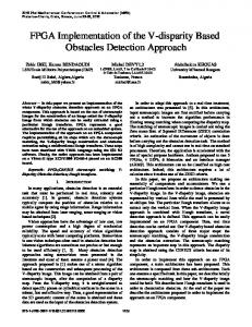
The design using counter requires less additional hardware and implemented using D flip flop Fig. 5 and Fig. 6. A SF register, holding the required spreading factor, controls the counter cycle, while the index register controls the specific OVSF code. This separation of the high level parameters SF and N provides modularity of the circuit blocks when multiple OVSF codes are generated. The entire design is reconfigurable using parameterized variable i.e. SF. Once the design is verified, a hardware co-simulation block can be generated and then will be used to program the Virtex-5 device (XC5VLX50T-lffll36) FPGA for implementation [10][11]. Fig.-9 shows the implemented model with ChipScope Pro block for testing in Xilinx System Generator. The bit stream download step is performed using a JTAG cable. The maximum synthesized frequency corresponds to ~ 470 MHz with minimum period 2 ns which is lesser than delay per chip for WCDMA i.e. 260 ns [12]. Fig. 6 shows the conventional method for testing using ChipScope Pro with software cores and variable test clock frequencies from 1 MHz to 10 MHz . Figs. 7 and 8 shows our test setup with (Integrated logic analyzer) ILA core. Test results are shown in Figs. 10 and 11. The behavioural and post simulation are supported by Mentor Graphics ModelSim tool as shown in Fig. 9. Table-2 Shows the Simulated Delays for OVSF Codes
S.No.
Parameter
Values
Fig. 7 Experimental Setup with Laptop, Platform Cable USB (JTAG) and BUT (Virtex-5, Genesys FPGA board) Table 3 Device Utilization Summary for Genesys Board (DIGILENT) 1
Device Utilization SL 5lice Logic Utilization 1 Number of Slice Registers Number used as Flip Flops Number of Slice LUTs Number used as logic
Used
Available 6
Utilization
44,300
Hote(s} 1%
S 7
44.300
i%
7
44,300
is
11,200
i%
Number using OS output only
3
Number using 05 and 06
4
Number of occupied Slices
3
Number of LUT Flip Flop pairs used
9
Number with an unused Flip Flop
3
■?
Number with an unused LUT
2
9
22%
Number of full'/ used LUT-FF pairs
4
0
44%
1 2
Minimum period
2.133 ns
Min input arrival time before clock
2.58 ns
3
Maximum output time req. after clock
4.921 ns
[■lumber of BUFG/BUFGCTRLs
4
Maximum combinational path delay
5.439 ns
Average Fanout of Non-Clock Nets
1
,
'^.r^be' 0* ^-.-i.s :o 'r;^ sets Number of slice regisler siles lost to control set restrictions Number of bonded IOBs
Number used as BLIFGs
2013 International Conference on Advanced Electronic Systems
3j%
1 2
44.300
1%
17
S40
2%
I
32
1 2.13
90
LI
Fig. 8 System Generator model for generation of HW-SW Co-simulation for OVSF Codes
Winiuuuuii¥
wuwiruuuu
injuinjuuinj
SiiibilSnlMiiJieifciifrilMiHfijdbrffaihii Fig.-9 Simulated Waveforms of OVSF Codes in ModelSim (SF = 6)
Fig. 10 Simulated Waveforms (for verification) in ChipScope Pro based logic analyser. Data port (0) for OVSF and Data Port (1) for Clock
Fig. 11 Simulated Waveforms (for Verification) of OVSF Codes in MATLAB Simulink
2013 International Conference on Advanced Electronic Systems
91
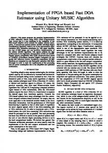
The ChipScope tool provides the ability to define and generate a customized ICON (integrated controller) core to use with one or more ILA, VIO (virtual input/output), or ATC2 (Agilent trace core) capture cores in HDL designs [13] [14]. The Integrated Logic Analyzer (ILA) core is a customizable logic analyzer core that can be used to monitor any internal signal of design. Since the ILA core is synchronous to the design being monitored, all design clock constraints that are applied to design are also applied to the components inside the ILA core. We have included ILA core and followed the testing flow as shown in Fig. 12.
constraints from the critical path delay of the synthesized circuit i.e. 2 ns which is significantly smaller than chip duration i.e. 260 ns for WCDMA standard. IV.
V.
[i]
[2]
[3]
[4] [5] [6] [7] [8] [9] [10] [11] [12] [13] [14] Fig. 12 ChipScope Pro Tool Design Flow for Testing III.
CONCLUSIONS
ACKNOWLEDGMENT
The authors would like to thank Mrs. Anu Gupta, HOD Department of EEE, BITS-Pilani and CSIR (MHRD, DELHI). This work is published with the support of CSIR (MHRD, DELHI) SRF Fellowship. REFERENCES
A. Richardson "WCDMA Design Handbook" Cambridge University Press, 2005. A. Baier, U. C. Fiebig, W. Granzow, W. Koch, P. Teder, and J. Thielecke."Design Study for a CDMA-Based Third-Generation Mobile Radio System." IEEE Journal on Selected Areas in Communications, Pp. 733- 743, May 1994. R. Fantacci and S. Nannicini. "Multiple Access Protocol for Integration of Variable Bit Rate Multimedia Traffic in UMTS/DVIT2000 Based on Wideband CDMA", IEEE Journal on Selected Areas in Communications, Pp. 1441-1454, August 2000. Y. S. Chen, T. L. Lin," Code Placement and Replacement Schemes for WCDMA Rotated-OVSF Code Tree Management", IEEE Transactions on Mobile Computing, Pp. 224 - 239, January 2006. B. D. Andreev, E. L. Titlebaum, E. G. Friedman," Orthogonal Code Generator for 3G Wireless Transceivers", GLSVLSF03, Proceedings of the ACM, Pp. 229 - 232, April 2003. S. Kim, M. Kim, C. Shin, J. Lee ,Y. Kim /'Efficient Implementation of OVSF Code Generator for UMTS Systems", PacRim 2009, IEEE Pacific Conference, Pp. 483 - 486, August 2009. J. S. Lee, L. E. Miller, "CDMA Systems Engineering Handbook", Artech House 1998. D. M. Baek, K. D. Joh, J. U. Kim, "Real-Time Processing of a Software Defined W-CDMA Modem", IEEE Vehicular Technology Conference, Pp. 1959 -1962, September, 2004. Rintakoski T., Kuulusa M, Nurmi J., "Hardware Unit for OVSF/Walsh/Hadamard Code Generation", System-on-Chip International Symposium on,Pp. 143 - 145, November 2004. Xilinx System Generator User's Guide, www. Xilinx.com. Available: [online] http://www.3gpp2.Org/public_html/specs/c.s0002-d_vl.0_021704.pdf. Digilent FPGA Board user's guide. Available: [online] http://www.digilentinc.com/Products/Detail.cmi?Prod=GENESYS Third Generation Partnership Project; Technical Specification Group Radio Access Network; 25.213, Spreading and Modulation, Release 5, www.3gpp.org, September 2002. Arshak, Khalil, Jafer E., Ibala C," Testing FPGA based digital system using XILINX ChipScope logic analyzer", 29th ISSE. on Electronics Technology, Pp. 355 - 360, May 2006. Xilinx ChipScope Pro 13.1 Software and Cores user guide. Available: [online] http ://www.xilinx. com/support/documentation/swmanuals/xilinxl 3_ 1/chipscope pro sw cores ug029.pdf
In this paper, the Parameterized OVSF code is implemented with maximum synthesized frequency i.e. 470 MHz. This flexibility is essential for UMTS transceivers, since signals of variable content and data rate requirements can be transmitted or received by changing the number and spreading factors of the channelization codes as specified by the 3GPP standard for WCDMA FDD/TDD system with maximum SF= 512. The design is further tested by simple flow using ChipScope Pro ILA core. Testing conforms the MATLAB Co-simulation results without any timing
2013 International Conference on Advanced Electronic Systems
92