Jun 15, 2016 - grammable Gated Array (FPGA) using MATLAB- system generator ... Switched Reluctance Motor, Speed Control, Optimized Switching Angles, ...
Circuits and Systems, 2016, 7, 1530-1545 Published Online June 2016 in SciRes. http://www.scirp.org/journal/cs http://dx.doi.org/10.4236/cs.2016.78134
FPGA Based Speed Control of SRM with Optimized Switching Angles by Self Tuning P. Saravanan, R. Arumugam, M. Senthil Kumaran Department of Electrical and Electronic Engineering, SSN College of Engineering, Kalavakkam, India Received 19 March 2016; accepted 15 April 2016; published 15 June 2016 Copyright © 2016 by authors and Scientific Research Publishing Inc. This work is licensed under the Creative Commons Attribution International License (CC BY). http://creativecommons.org/licenses/by/4.0/
Abstract The electromagnetic torque and speed in Switched Reluctance Motor (SRM) greatly depend on the excitation parameters i.e. turn-on angle, turn-off angle, dwell angle and magnitude of the phase currents of its phases. At lower speeds, a change in the current contributes the torque requirement which can be achieved either by voltage control (pulse width modulation) or instantaneous current control techniques. At high speeds, due to high back EMF, the regulation of current is crucial and achieved with the control of switching angles of phases. This type of control is referred as average torque control, where the torque is averaged over one stroke ( 2π N r ) . With constant dwell angle, advancing the phase angle influences the current into the phase winding at minimum inductance position. It has more time to get the current out of the phase winding before the rotor reaches the negative inductance slope. To maintain the speed of the motor at different load conditions, the turn-on and turn-off angles are adaptively varied. The change in dwell angle may be required where the turn-on and turn-off angle may not be sufficient to reach the required speed. In this paper, a new algorithm is proposed for self tuning of switching parameters of SRM. The proposed algorithm is simulated in MATLAB-Simulink and experimentally validated with Field Programmable Gated Array (FPGA) using MATLAB- system generator environment.
Keywords Switched Reluctance Motor, Speed Control, Optimized Switching Angles, FPGA, Nexys-4, MATLAB-System Generator
1. Introduction Switched Reluctance Motor (SRM) runs by reluctance torque. It has many advantages compared with other drives such as simple construction, low cost and highly fault tolerant. The torque-speed characteristics of the How to cite this paper: Saravanan, P., Arumugam, R. and Kumaran, M.S. (2016) FPGA Based Speed Control of SRM with Optimized Switching Angles by Self Tuning. Circuits and Systems, 7, 1530-1545. http://dx.doi.org/10.4236/cs.2016.78134
P. Saravanan et al.
motor can be modified as per the requirement of the application starting from the design stage. High starting torque and extremely high speed are possible. DC motors are preferred for variable-speed applications whereas AC motors with constant frequency have been used for constant speed applications. In contrast, SRM has a wide range of constant torque and power regions. The speed and average torque can be controlled by varying any one or indeed all of the switching parameters. The combinations of these depend on the performance requirements, permissible level of complexity, and cost. Attempts have been made to estimate these parameters [1]-[7]. Some of the early optimization methods assume non-saturable inductance and were valid for fixed speed and load, which needs extensive simulations of the machine model. A simple thumb rule is used to choose the turn-on angle. The position of rotor and turn-on angle was calculated with a phase lock loop system and a micro controller (Intel-8751) [8]. In [9], only turn-on angle has been tuned automatically based on the peak phase current and implemented with Digital Signal Processor (DSP). Turn-on angle defines the maximum average torque while the turn-off angle derives maximum efficiency [7]. The analyses with fixed turn-off angle and varied turn-on angles were presented in [10]. Online fine tune of turn-on angle with the pre-existing methods for better performance was addressed in [11] and high resolution position encoder was required for implementation. Optimal turn-off angle to attain maximum torque is maintained by self tuning, and the number of pulses from the encoder is counted to find the position of the rotor [12]. The critical issues in the closed loop speed control of SRM based on the lead angle (turn-on) and conduction angle (dwell angle) have been addressed and control of the angles is implemented with micro processor, which can perform 1000 operation per second (Z-80, 2.5 MHz). The accurate position and phase current information are fed to the system to calculate the angle of advance [13]. To have the optimum torque output, an analytical concept was introduced [1]. It has some state variables and current by assuming a stepwise linear inductance profile is introduced to calculate the switching angles. The implementation was not discussed, as it required accurate position of the rotor. At certain scenario, the change in switching angle at run time degrades the transient response. To overcome this issue, off-line optimization of switching angles was developed [5] [6]. Optimal switching angles have been calculated at offline to have the maximum average torque and framed a look up table to refer, at run time [5] [14] [15]. Two separate controllers have been used for calculating on and off angles. Calculation of turn-off angle needs the flux linkage waveform of the two neighboring phases [11] [16]. A control algorithm has been designed for a wide range of speed with automatic tuning for efficient torque production. It consists of two parts for below and above rated speed. This has been implemented in DSP, with the achieved speed range of 500 to 2500 revolutions per minute (RPM), rated speed of 1500 RPM. Based on the rotor position information, a self tuning approach has been presented [17]. The digital control issues and solutions were addressed with the self tuning algorithm, which has been tested for maximum speed [18]. At present the design of pumps and aerospace drives requires high speed and ultra high speed drives. Due to the complex structure of rotor, the stress on rotor at high speed and the demagnetization of magnetic materials under high temperature limits the application of permanent magnet motors to these applications. SRM has been the right candidate for the high speed application and can be made to run at ultra high speed. The feasibility of the ultra high speed for 1 kW, 6/2 SRM made by composite materials has been tested with the speed of 200,000 RPM in France [18]. A 30 kW SRM with the speed of 52,000 RPM has been developed for gas turbine application [19]. The angular position control for the high speed 6/2 SRM, and the maximum speed of 130,000 RPM has been realized with a special ASIC SR3P10K07A in China [20]. From the literature the technique behind the implementation of the turn-on, turn-off and change in dwell angle for speed control have not been addressed as it requires a high resolution position encoder. In this paper a self tuning algorithm has been developed to vary the speed by varying the excitation parameters without high resolution position encoder. It has been validated in a 8/6 pole, 0.5 hp SRM and also tested in loaded condition. It uses the digital position sensors which changes its values for every 15˚ of rotor rotation. The proposed algorithm has been simulated in MATLAB and it is found to have good dynamic control of the motor. The same was experimented with Xilinx NEXYS-4 FPGA Board using MATLAB- system generator. Following assumptions are made in order to facilitate qualitative development of algorithm. 1) The winding inductance is a linear function of rotor position. 2) Phase power switching devices are all ideal and switching is achieved instantaneously. 3) Power losses are ignored.
1531
P. Saravanan et al.
The rest of the paper is organized as follows: Section 2 presents description of the system and control principle. The proposed algorithm and techniques to achieve the desired control is discussed in the Section 3. The simulation of algorithm and the results are given in Section 4. The analysis and real time implementation of the algorithm with FPGA are presented in Section 5.
2. Theory and System Control Strategy SRM is an electric motor in which torque is produced by its movable part to move to a position, where the inductance of the excited winding is maximum [20]. SRM has simple and robust structure. Due to the absence of magnets and rotor windings it became very popular among variable speed drives. When the rotor poles are aligned with the stator poles, diametrically opposite stator poles are excited. In the same position another set of rotor poles are out of alignment with respect to a different set of stator poles. The rest of the stator poles are excited to bring another set of rotor poles into alignment. By switching the stator phases sequentially, the rotor is put into continuous motion. The direction of the rotor and generation of the torque is based on the switching sequence of the stator phases.
2.1. Control Principle The phase windings of the motor are excited at the onset of increasing inductance, producing positive torque. Before the start of negative inductance profile, current must be commutated to avoid negative torque and hence torque ripples. The voltage equation of SRM can be written as [21] v =Ri + L
dL (θ , i ) di + ωi dt dθ
(1)
di The voltage Equation (1) consists of resistive voltage drop ( Ri ), inductive voltage drop L and back dt dL (θ , i ) EMF or motional EMF ωi respectively. It can be written as dθ v= Ri + ω L
dL (θ , i ) di + ωi dθ dθ
(2)
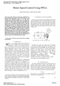
At high speeds in order to maintain the rated current, the power switches along with the phases are kept ON throughout the stroke. Now the chopping of voltage would reduce the average applied voltage and hence the current and torque. The peak flux linkage during the stroke is given as Vsθ d ω , where θ d , ω are dwell angle and speed respectively [22]. Due to high back EMF, the supply voltage is insufficient for chopping the current. Figure 1 shows a cycle of inductance profile, flux and current waveform of single phase of SRM [23]. If θ o of winding is advanced by θi on the onset of the rising inductance region, the inductance of the circuit is minimum. This allows the current to build up rapidly. When the inductance profile starts increasing, the rising inductance and back EMF causes the current to fall until the switch is opened at some angle θ x . When the switch is OFF, due to opposing polarity being applied to the winding, the current flow starts decreasing more rapidly. To maintain peak flux at higher speeds, dwell angle must be increased proportionally with speed [23]. Let v0 be the phase voltage at the unaligned inductance region and the corresponding current be i0 . Neglecting the resistive drop, Equation (2) at unaligned position can be rewritten as
= v0 ω Lu
di0 dL + ωi0 u dθ dθ
where Lu , the unaligned inductance which is constant. Hence
∴ v0 α
di0 dθ
(3)
dLu =0. dθ (4)
With the above relation, it is inferred that advancing the phase excitation (θ), will increase the current ( i0 ) for constant voltage ( v0 ). The torque equation of SRM is given as
1532
P. Saravanan et al.
Figure 1. Flux, current and linear variation of inductance waveforms.
Te (θ , i ) − T= J l
dω + Bω dt
(5)
Te (θ , i ) is the electromagnetic torque developed; J is the moment of inertia of both stator and rotor; Tl load torque and B is the friction coefficient. As B is very low, B ≈ 0 and Te (θ , i ) =
i 2 dL (θ , i ) 2 dθ
(6)
From (5), (6) dω 1 i 2 dL (θ , i ) = − Tl J 2 dθ dt
(7)
For constant Tl and J, increasing current will increase accelerating torque and hence increases the speed.
2.2. Calculation of Turn-On and Turn-Off Angle The turn-on and turn-off angles are the variables with respect to the speed of the motor and controller parameters. With increasing speed, fixed turn-on, turn-off angles may decrease electromagnetic torque and cause tail current, which leads to negative torque. To attain the maximum torque and efficiency, the switching parameters have to be adjusted proportional to speed. It is proposed that the calculation of turn ON angle of SRM as [8],
θ on= θ m − 6
Lna ∗ N m I Vdc
(8)
In [4] the proposed turn-off angle theory with the assumption of non-saturable, piecewise linear gauge curve model, given as
24 ∗ I ∗ (1 − x ) ∗ N m θ off = θ a − θ m −α + α 2 + Rua ∗ Vdc ∗ θ m
1533
(9)
P. Saravanan et al.
α=
Ra Rua
(10)
Rua = Ru − Ra
(11)
where Ra and Ru are reciprocals of the aligned (La) and unaligned (Lna) inductances. N m , speed (RPM); Vdc , DC link voltage (V); 2 1 and ); x is a constant (usually between 3 2 I is phase current (A); θ m is rotor position middle angle (˚).
3. Proposed Algorithm The assumption of non-saturable inductance for the estimation of turn-off angle does not hold good for complete range of current [6]. The calculation of turn-on and turn-off angles at run time, increases the computations and thereby time consuming, made inappropriate for high speed of operations. A look-up table with pre-calculated turn-on and turn-off angles can be used, but the intermediate values have to be calculated using interpolation technique. Equations (8) and (9) are used to calculate turn-on, turn-off angles respectively for various current and speed at offline. It is inferred that the minimum required change in excitation parameters is 1%, hence the algorithm is structured to change the excitation parameters by 1% till the desired speed is reached. The proposed algorithm is for 8/6 pole 4 phase SRM can be modified for any number of poles and phases. In � this motor all the four phases has to be excited once in a stroke, with the stroke angle of 60 ( 2πNr ) . According � to the stator and rotor pole geometry, allowable dwell angle for the phase excitation is 15 to the maximum of 30� to avoid negative torque and torque ripples. From the two digital position sensors the position of the rotor poles are found for every 15˚ and the excitation patterns are derived using decoder. Consider the excitation of phase 3, as shown in Figure 2 the dwell angle starts at 30� and ends at 45� with respect to rotor position. It should be noted that the maximum allowable dwell angle is 30� and θON starts from 15� . At same instant the excitation ( θON ) of phase 2 also starts. The delay in phase excitation can be done with the inclusion of a delay routine program, after sensing the phase excitation signal. But it is difficult to advance the phase excitation as it requires the assumption of turn-on time. Hence to advance the dwell angle a new logic is presented as follows. The maximum dwell angle for any phase is calculated by logical OR of the excitation pattern of present phase and its previous phase. For instance, to estimate the maximum dwell angle for phase 3, the excitation signals of phase 3 and phase 2 from the decoder are logically ORed. The maximum dwell angle for phase 3 is from 15� to 45� of rotor position, during this interval required θON and θOFF to reach the set speed is fixed. The ORed signal (VO ) which has been used to generate PWM for the phase is integrated. The output of the integrator is in the form of saw tooth (Vint ) . A variable 'K' is defined with initial value of the time taken by the rotor to move 30˚. It is calculated from the speed of the motor and equivalent to the width/height of the saw tooth of integrated wave. Figure 3 shows the PWM wave generated for the excitation of the phase, according to the conditions given in (8). where V ph is the supply to the phase windings. With increase in 'K', the pulse width gets reduced and hence dwell angle. 1 V ph = 0
if K 2 < Vint if K 2 > Vint
(12)
With a change in motor speed, the new value of K is calculated, by comparing the set speed with actual speed. If the difference is positive, the K value is decreased by 1%, else K increased by 1%. For the 8/6 pole SRM, 1% corresponds to 0.15˚. This procedure is repeated till the set speed is attained. It is expressed by Equation (9) as follows.
K + 0.01K if ωa > ωs K = K − 0.01K if ωa < ωs K if ωa = ωs
1534
for
1 3 K