Functional Representation as Design Rationale B. Chandrasekaran Laboratory for AI Research 2036 Neil Ave The Ohio State University Columbus, OH 43210
[email protected]
Ashok Goel Yumi Iwasaki Department of Computer Science Knowledge Systems Lab Georgia Institute of Technology Stanford University Atlanta, GA 30332 701 Welch Road
[email protected] Stanford, CA 94305
[email protected]
Abstract: Design rationale is a record of design activity: of alternatives available, choices made, the reasons for them, and explanations of how a proposed design is intended to work. We describe a representation called the Functional Representation (FR) that has been used to represent how a device's functions arise causally from the functions of its components and their interconnections. We propose that FR can provide the basis for capturing the causal aspects of the design rationale. We briefly discuss the use of FR for a number of tasks in which we would expect the design rationale to be useful: generation of diagnostic knowledge, design verification and redesign.
Keywords: Design rationale, functional representation, causal models, redesign, design problem solving, concurrent engineering.
Functional Representation as Design Rationale
01/28/93
Design Rationale and Its Uses The design process involves exploration of design spaces, simulation and verification of candidate designs, possible redesign and repetition of the cycle. The body of information that explicitly records the design activity and reasons for various choices (including reasons for not making some choices) has been called the design rationale (DR). As more and more of the design process is coming under computational support, interest has begun to focus on making design rationale explicit and putting it in a form that can be recorded and possibly manipulated computationally. What kinds of information DR should contain and how to express them have been topics of recent research in design. A recent special issue1 of the journal Human Computer Interaction was devoted to DR. Maclean, et al,2 propose a semiformal notation, called QOC (Questions-Options-Criteria), to represent the design space. As the design space is explored, Questions identify key design issues, Options provide possible answers to these, and Criteria help assess the options. Lee and Lai3 propose a language called DRL which provides a vocabulary in which design alternatives, the evaluation space and criteria, and the argument structure in which design discussions are conducted can be recorded. Lee and Lai3 make a useful distinction between (i) design rationale as a record of the exploratory activity of the design team (along the lines of the information captured by the QOC formalism) and (ii) as an account of how the designed artifact serves or satisfies the expected functionalities. The distinction is essentially one of describing the activity of the designers (what alternatives were considered and what choices were made and why) versus describing the functioning of the artifact. In this paper we consider the use of a representation called the Functional Representation (FR) for describing how the device works (or is intended to work). Specifically, we wish to show how FR can be used to capture the causal component of DR, i.e., designer's (or the design team's) account of the sequence of causal interactions among its components that lead to the achievement of the device functions. Some of the possible uses to which a design rationale can be put are:
2
Functional Representation as Design Rationale
01/28/93
i. Controlling distributed design activity. In concurrent engineering, DR for design choices and decisions by one group can be used by other design groups to avoid redundancy of effort and incompatible design choices. ii. Reassessment of device functions: During the period of use of the device, the component values might drift or even change qualitatively. Users might examine the DR to see if the device can still be expected to achieve the functions or evaluate the deviations from the expected range of behavior. iii. Generation of diagnostic knowledge: DR can be used to generate diagnostic procedures, thus helping in maintainability. iv Simulation and design verification: DR can be used to evaluate if the device will in fact perform as intended. In particular, the information in the DR can be used to focus and control device simulation to verify the expected functions. iv. Redesign, Case-based design: It may be desired to change the function of a given device. If the intended change is not drastic, perhaps much of the structure can be retained. The design rationale may be used to identify the components, subsystems or parameters that need to be changed, thus avoiding designing again from scratch. Similarly, when a new device is being designed, previous designs can be examined to see which of these are close in functionality to the new device. The design that requires the least modification can be chosen and modified (case-based design). The design rationale can be useful in identifying the design that is "closest" to the desired device and also identifying the places where this design needs modification.
Goals of the Paper : In the rest of the paper, we outline the main elements of the Functional Representation (FR) language for capturing design rationale, and describe how this representation can be helpful in the performance of some of the above tasks.
3
Functional Representation as Design Rationale
01/28/93
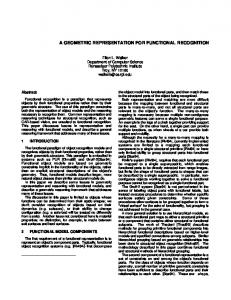
Functional Representation Functional Representation (FR) is a representational scheme4 for the causal processes that culminate in the achievement of device functions. (Not all devices are best viewed as achieving their functions by means of causal processes. We discuss this later.) The approach taken in FR to representing a device is top-down in the sense that the function of the overall device is described first and the behavior of each component is described in the context of the function. This is in contrast to the bottom-up approach taken in many behavior-oriented knowledge representation and reasoning schemes. (See sidebar). In FR, the function of the overall device is described first and the behavior of each component is described in terms of how it contributes to the function. Figure 1 is a schematic of a device called the Nitric Acid Cooler 5 (NAC) which we will use as one of the expository examples in this paper. In FR, we represent the structure and function of a device and the causal processes that take place in it. We use as primitive notions the ideas of a system, input to the system and output behavior of the system. A device is a system with some intended inputoutput relations, called functions. A component of a device is itself a system characterized by its own functions. Often classes of functions and components can be described by use of parameters. In the NAC example, component class pipe(l,d) describes pipes with length l and diameter d , while pipe2 is a specific instance of pipe(l,d) with specific values for l and d. Similarly, the device NAC as a class has a function cool-input-liquid(rate, temperature-drop) where rate and temperature-drop are capacity parameters of the function cool-input-liquid. A particular NAC might be identified by specific values for these paramaters. Devices can have substances whose properties are transformed as part of their functions. Substances can be destroyed and new substances created. Substances can be physical (e.g., nitric-acid) or abstract (e.g., heat). In the NAC example, the substance nitric-acid has properties temperature, flow rate, and amount of heat (which itself is a substance). Components are configured in specific structural relations to each other to make a device. Components thus have ports at which they come together with other components in certain relations. In an electrical circuit, electrical components are electrically-connected at the defined terminals. In the NAC example, the relations include conduit-connection, containment, etc. (The relational vocabulary
4
Functional Representation as Design Rationale
01/28/93
can also include unintended relations, e.g., electrical leakage between electrical components. The components can be in unintended relations to each other as a result of malfunctions.) The vocabulary of relations is domain-specific. The semantics of the relations are established by the domain laws that govern the behavior of the components in the given relations.
Hot H2O
p7
Hot HNO3
Cold HNO3 p2
p1
p3
pipe1
p4
pipe3 pipe2 p6
Heat-Exchange Chamber (HEC)
Cold H2O p5
Water-pump Note on ports . Device ports : p1, p4, p5 and p7. Water-pump port, Input, is the same as device port p5 Water-pump port, Output, is the same as HEC port Input-port, which is the same as device location p6. HEC's Output-port is the same as device port p7.
Figure 1. Schematic of a Nitric Acid Cooler Structure of a device. The structure of a device is a specification of the set of components that constitute the device and the relations between the components. The components are represented by their names and by the names of their functions, which are all domain-specific strings. Components can have variables for its parameters. All components have ports at which they are connected to other components. For example, the component type "pipe" might be written as pipe(l,d;t1,t2), where l and d are the length and diameter, and t1 and t2 are the input and output ports. The FR languge uses the following keywords for describing structure: Structure((Device(, , )),
5
Functional Representation as Design Rationale
01/28/93
Component(, , ), Function(), Relation().
For example, the structure of NAC can be described as follows: Structure((Device(NAC; cooling-capacity and temperature parameters, ports: p1, p4, p5, p7)) Components: pipe1(l1, d1; p1, p2), pipe2(l2,d2;p2,p3),pipe3(l1,d1;p3,Output) Heat-exchange-chamber(, Input-port, output-port) Water-pump(Input, Output) Function(pipei): Conduit (input, output) Function(Heat-exchange-chamber): exchange-heat() Function(Water-pump):........ Relations: Component(pipe2) contained-in Component(Heat-exchange-chamber) Component(pipe1) conduit-connected (pipe2) {Ports: } Component(Water-pump) conduit-connected Component(Heat-exchange-chamber) {Ports: }
The terms in italics are domain-specific names for functions, components, relations, etc. The interpreter for FR treats them as strings. The terms in Courier are terms in FR (and hence in DR). Additional domain-specific intepreters may be able to use the italicized terms as meaningful keywords. For example, a mechanical simulator can use terms such as contained-in and conduit-connected to perform simulations. For the purpose of this exposition, they are to be understood in their informal, English-language meanings. The syntax of the Relations keyword is that an n-ary relation has n components and a ports term indicates which ports of the components are connected. Note that the components are described purely in terms of their functions. This makes it possible in principle to replace components by structurally different but functionally identical components. Further, the components themselves can be represented as devices in their own terms. 6
Functional Representation as Design Rationale
01/28/93
States and Partial States. A device state is represented as a set of state variables consisting of values of all the variables of interest in the description of the device. State variables can be either continuous or discrete. In particular, some of the variables may take truth values {T,F} as their values, i.e., they are defined by a predicates. An example of a continuous variable is water temperature in a device that uses water for cooling a substance. An example of a variable defined by a predicate is "open?(valve)" This variable will take values T or F depending upon whether the valve is open or not. In describing functions and causal processes, we generally talk in terms of partial states of the device. A partial state is given by the values of a subset of state variables. For example, the partial state (call it state1) of NAC (describing some relevant state variables at the input p1 of the device can be given as {substance: nitric acid; location(substance): p1, temperature(substance): T1}. State2, describing the properties of nitric acid at location p2, will only differ in the location parameter, while the partial state description, state3, at location p3 will be {substance: nitric acid; location(substance): p3, temperature(substance): T2}, where T2 < T1. The language in which states are represented is itself not part of FR and is largely domainspecific. In economics, the state variables would be entities such as GNP, inflation-rate, etc; in nuclearplants, the entities would be "radiation-level, " and so on. Goel5 has defined a state description language which is useful in describing devices that deal with material substances that change locations, e.g., those in which substance flow is a useful notion. The state representation that we just used for NAC uses this language. Causal Process Description. The intuitive idea is that we understand how devices work by building a causal description of how the device goes through various states until the desired state is reached, and we explain the causal transitions between states by appealing to the functions of components and domain laws (such as scientific laws). The causal process description (CPD) is a directed graph with two distinguished nodes, Ninit, and Nfin. Each node in the graph represents a partial description of a state of the device. Ninit corresponds to the partial state of the device when the conditions for the function are initiated (such as turning a switch on). Nfin corresponds to the state 7
Functional Representation as Design Rationale
01/28/93
where the function is achieved. Each link represents a causal connection between nodes. One or more qualifiers are attached to the links to indicate the conditions under which the transition will take place, and one or more annotations can be attached to indicate the type of causal explanation to be given for the transition. The graph may be cyclic, but there must be a directed path from Ninit to Nfin. Let us consider the NAC example again. Let nodes state1, state2 and state3 correspond to the states of nitric acid at the input to pipe1, at location p2 and and location p3, respectively. Figure 2 depicts the CPD graph (without any annotations or qualifiers) describing what happens to the nitric acid and the water as they flow through the chamber. We have represented the nodes in informal English, but they can be described more formally similar to our description of state1.
state1
state2
state3
CPD-1 : HNO3 at temp T1 at location p1
HNO3 at temp T1 at location p2
HNO3 at temp T2 (T2 < T1) at location p3
CPD-2 : Water at temp T3 at input to water-pump
Water at temp T3 at input to Heat-exchanger
Water at tem T4, T4 > T3 at output of Heat-exchanger
Note : state1, state2 and state3 are described more formally in the text. The transition from state2 to state3 is described in Figure 3 with annotations and qualifiers.
Figure 2. CPD's for device NAC (without link annotations) We have identified three types of annotation for explaining a causal transition: appealing to another causal process, to a function of a component, and to domain laws (so-called first principles). Let us elaborate on the three different types of knowledge used for explaining a causal transition. i. By-CPD: In explaining the transition "water heated --> steam created," we can point to the causal-process of "boiling," which is part of the commonsense knowledge of most humans. The agent for whom the explanation is intended will accept the explanation if she already has an
8
Functional Representation as Design Rationale
01/28/93
understanding of the process as part of her background knowledge, or the details of the process do not matter to her current purpose, or, if the details mattered, she can ask for a more detailed explanation of the causal transitions involved in "boiling." In any case, this form of explanation enables the process explanation to be hierarchically composed out of other process explanations, making explanation at each level shorter. Once "boiling" is understood, it can be reused, possibly after instantiating some parameters (e.g., the pressure at which the boiling is done, the liquid that is being boiled, and so on), whenever it is needed as explanation for other processes. Human expertise in a domain contains knowledge of a large number of such causal processes that can be parametrized and re-used. ii. By-Function-Of- : In an electrical circuit, the state transition, "Switch(on) ---> Voltage v at the terminals" might be explained by pointing to the function of the battery as a source of voltage, i.e, by the annotation, "by-Function(voltage generation) of component(battery)." In fact a major goal of causal explanation in devices is to explain the behavior of the device in terms of the properties of the components and their inter-connections. Again, a large part of expertise of human experts in a domain is in the form of knowledge about generic components and their functions, even if the details of how the component functions may not be known. The ability to explain the device functions partly in terms of component functions, and to explain component functions in turn in terms of the functions of its subcomponents helps in the formation of functional/component hierarchies in explanation and design. iii. By-Domain-Law . Another form of explanation is by appeal to domain laws. In the domain of engineering, scientific laws are the ultimate basis of explaining why the device behaves as it does. For example, the state transition, "5 Volts at the input -----> 2 amps thru the load" might be explained as "By-Domain-Law(Ohm's-Law: Voltage = Current * Resistance)".
9
Functional Representation as Design Rationale
01/28/93
For a particular device, any realistic FR description will taper off at some level of components and CPD's. This is an example of the incompleteness inherent in FR and design rationale in general. The function of a device (or a component) itself is, as we shall see, explained by pointing to a CPD. When we use a By-Function annotation, we are actually pointing to a CPD that is part of the explanation of that function. The difference is two-fold. One, in how the CPD's are indexed; in the case of a By-CPD annotation, we are pointing to a piece of prior knowledge explicitly labeled as a causal process, while in the case of a By-Function annotation we are pointing to prior knowledge of a component function. Two, in the case of a component function, there may well be no explicitly available CPD that explains the function." Often we know many components only by their function. Sometimes additional, noncausal, links may need to be added to arrive at the predicate of interest. For example, for an amplifier, we may have constructed the CPD, Voltage 1 at the input -->.......----> Voltage 10 at the output, but the function that needs to be explained might be "Amplification of 10." A non-causal, definitional/abstraction link can be used to arrive at the node "amplification of 10" from "Voltage 10 at the output." Such links can be used to indicate an inference that follows from predicates in the earlier nodes. In addition to annotations, the links may have qualifiers which state conditions under which the transition will take place. In FR the qualifier Provided(p) is used to indicate that condition p should hold during the causal transition for the transition to be initiated and completed, and If(p) to indicate that the condition p should hold at the moment when the causal transition is to start. The conditions can refer to the states of any of the components or substances. Many of these qualifiers are eventually translated as conditions on the structural parameters. Figure 3 shows one fully annotated causal transition in the Nitric-Acid-Cooler. It uses two functional and one domain law annotations, and uses conditions on the structure and substances as qualifiers. The qualifiers include conditions on the properties of the substance (it should be a liquid of
10
Functional Representation as Design Rationale
01/28/93
low acidity) and structural conditions (the chamber fully encloses pipe2). Note that a transition may have more than one annotation or qualifier.
state2
state3 By-function allow-flow (substance) of pipe2{end1, end2, space2} Qualifier : (substance(property(state-of-matter: "liquid", acidity: "low"))) By-function allow-flow (heat) of {sides-of{pipe2{end1, end2, space2}} Domain-law: zeroth-law-of-thermo-dynamics Qualifiers: (appropriate enclosures of pipes in chamber)
Figure 3. Annotations and qualifiers for a causal transition in NAC .
Functions. Every device has intended functions. Keuneke6 has identified four types of functions: ToMake, ToMaintain, ToPrevent, and ToControl. Formal definitions of these function types have been developed7, but for our current purposes the following informal ones should suffice. All the function types above except ToControl take as argument a predicate, say PF, defined over the state variables of the device. The function is of the ToMake type if the goal is to make the device reach a state in which PF is true, and after that state is reached no specific effort is needed to keep the predicate's value to True, or it doesn't matter what state the device goes to after the desired state is reached. A function is of type ToMaintain if the intention is to take the device to the desired state and the device has to causally ensure that the predicate remains True in the presence of any external or internal disturbance which might tend to change the device state. The function type is ToPrevent if the goal is to keep PF from ever being true, and some active causal process in the device is required to ensure it. (Logically ToPrevent P can be written as ToMaintain (Not P), but there are important differences in practice. Pragmatically, a designer charged with making sure that the device doesn't
11
Functional Representation as Design Rationale
01/28/93
explode uses knowledge indexed and organized for this purpose. This prevention of explosion, say by using a thick pipe, is not the same as maintaining some dynamic state variable in a range.) The function type ToControl takes as argument a specified relation vo = f(v1,...vn) between state variables vo, v1,...vn, and the intent is to maintain this relationship. That is, we wish to control the values of specific variables as a function of the values of some other variables. A function F thus has the following descriptive elements:. Function () Device () Type () Start-Conditions(; the conditions under which the function will be initiated) Function-Predicate or Control-Relation(;the predicate that has to be reached, maintained or prevented, or the control relation that has to be maintained) By-CPD(; explains how the function is achieved)
Consider the example of a Nitric Acid Cooler in Figure1: hot nitric acid goes into a heat exchanger and exchanges heat with the water that is being pumped in. The water gets hotter while the acid gets cooler. The functional definition of NAC can be given as follows. Function (Nitric-acid-cooling) Device (NAC) Type (To-Make) Start-Conditions(Input temperature of Nitric Acid =T1) Function-Predicate(Outlet temperature of Nitric Acid = T2, T2 < T1) By-CPD(CPD-1 in Figure 2)
The complete FR is given by specifying the device name, its structure, the state variables of interest, the functions of interest, and the functional template including the CPD's. We have described the representational primitives needed for all the above.
12
Functional Representation as Design Rationale
01/28/93
Representing a device using FR. We have given an informal outline of the representational framework that we have called the Functional Representation. A language by itself does not fully specify how it should be used, so a few remarks on how FR might be used to explain device functions may be in order. First, there is no unique FR for a device. Different agents might describe how a device works in somewhat different ways. The differences might relate to the differences in how the explanation was decomposed, what background knowledge was assumed, and the intended uses of the causal explanation. Second, choices will have to be made about what functions need to be explicitly represented. While every device has intended functions, there are a number of implicit functions (e.g., the design specification of a TV set does not explicitly record that it is intended not to explode). Range of Applicability of FR. While functional representation as an idea is quite general, the set of primitives that we have discussed so far only covers a subclass of devices. Not all devices have functions which have to be understood as a result of a causal process that evolves temporally. For example, the device "chair" has a function "to support seating of a human." However, this function is not accomplished by any causal process which involves state changes. Instead the function is achieved by its shape. Bonnet8 has identified a function type called ToAllow to account for functions of this type. Second, FR discretizes continuous causal processes into node-to-node transitions where at each node some predicate of interest changes. There are many phenomena for which explanations have to appeal much more to the intrinsic continuity of the relevant component properties, e.g., behavior that depends on shapes of objects. Third, more research is needed to represent functions which have temporal relations between states as an essential part of the function definition. For example, an electronic sawtooth signal generator goes through a certain series of state changes of charging and discharging of its output capacitor. The function to be achieved corresponds, not to the device being in a single desired state, but to repeatedly cycling through a sequence of states with each state occupying as certain duration. Representing these aspects of a causal process is an open research issue. On the other hand, there is no real constraint that the devices have to be physical for useful FR's to be constructed for them. The FR framework has been used to represent computer programs and to reason about program
13
Functional Representation as Design Rationale
01/28/93
errors 9. FR has also been used to reason about many complex physical systems; references 4, 6, 7, 10 provide some examples. Many implementations exist for the FR language, with somewhat different syntax in each implementation. We have used a composite syntax, chosen mainly for expository effectiveness. We have suppressed many details by giving English language descriptions of the intended information within parentheses or curly brackets. For example, we say "qualifiers: (appropriate enclosures of pipes in chamber)" in Figure 3. A detailed syntax for representing the relevant relations about pipes is in fact available and used in5. Functional Representation as Design Rationale While FR does not encode what alternatives to a choice were available and why they were not made, it does provide a partial rationale for the choices of components and the configuration that were made. We say "partial" because the CPD encodes only the directly causal role of a component, but there could be other reasons for why the particular component value was chosen. Secondly, the role of a component in the achievement of a function might be distributed over several transitions and different CPD's, and the rationale for why a component was chosen the way it was might actually reflect these multiple constraints. In an electrical circuit, the real explanation of why a resistance was chosen to be 1000 Ohms might be that the resistance had to be less than 2000 Ohms for a specific transition, and it needed to be greater than 600 Ohms for another transition, and finally the choice was made as 1000 Ohms because that was a standard value at which it could be easily procured. The latter information is not part of the causal account, and thus is not directly represented in the FR. Earlier we identified a number of tasks that a design rationale should be able to support: diagnostic knowledge generation, simulation, design verification, and redesign. FR can support many of the above tasks to the degree that they require causal knowledge about the operation of the device. Of course, all these tasks can also benefit from information from other components of DR. In particular the redesign task often requires a knowledge of why certain choices were not made, and additional knowledge from other components of DR could be useful for those aspects of the task. In this section,
14
Functional Representation as Design Rationale
01/28/93
we give brief overviews of how FR can be used for diagnostics generation, design verification, and redesign. Generation of Diagnostic Knowledge: For simplicity, let us first consider a CPD in which each transition has only one annotation. Consider a transition in a CPD of the form by-function F- of-component c n1------------------------------------------------------> n2
Suppose the device is in the partial state n1, i.e., the device is in a state that satisfies the predicates corresponding to n1. Suppose we test the device and observe that the device fails to reach n2. What conclusions can we draw? Because the CPD asserts that the device goes from partial state n1 to n2 because of the function F of component c, we can hypothesize that the failure to reach n2 is due to the component c not delivering the function F. Corresponding to this transition we can identify a possible malfunction state "Component C not delivering function F." The diagnostic rule "device satisfies n1 but not n2," can be used to establish this malfunction mode of the device4. If the annotation had instead been "By-CPD CPD-1," where CPD-1 is a specific CPD, we could similarly examine CPD-1 to see why this transition failed (some transition in CPD-1 should fail if the transition from n1 to n2 failed). Ultimately, we can identify some function of some component that would have to be responsible for the failure of the device to reach n2. There is no malfunction corresponding to a transition with the annotation By-Domain-Law; a domain law cannot fail to hold. Of course, the designer's account of the role played by the domainlaw could be incorrect, but we are assuming here that the FR itself is correct. How to verify the design rationale itself is an interesting issue in its own right, but is not the subject of the current discussion. The technique of identifying a component malfunction either directly from the annotation ByFunction or by recursive application of By-CPD leads to a diagnostic tree that will have as leaf nodes malfunctions of components or subcomponents. The diagnostic rule for each malfunction will be composed of rules of the form "If the predicates corresponding to node ni are true, but those corresponding to nj are not true, then.." 15
Functional Representation as Design Rationale
01/28/93
What happens when we have more than one annotation, e.g., as in Figure 3 where the transition appeals to more than one function? In this example, the transition can fail because pipe2 is blocked, its thermal (heat exchange) function fails, or because the conditions in the qualifiers are not satisafied. In this case, the failure of the transition can only identify these as possible malfunctions, but cannot establish them. Additional information will be necessary. Note, however, that not all diagnostic knowledge can be derived from design information alone. For example, rank ordering diagnostic hypotheses in terms of likelihood and pursuing them in the order of most probable to least probable is quite common in diagnostic reasoning. But this ordering requires knowledge of probabilities of failure for components. This information is not derivable from a causal model of how a device works. Additional information in the form of failure rates is needed. Conversely, not all diagnostic knowledge derived from causal models is directly usable, since some variables mentioned in the diagnostic rules generated from causal models may not be directly observable. Additional inference may be required. Design Verification. Simulation is an important means for testing a design. By comparing the behavior predicted by simulation and the FR of the desired function of the device, one can verify whether the design will in fact achieve its functions in the intended fashion. There are two potential difficulties in using the FR and simulation results for design verification. First, there is a possible gap in levels of abstractions between the language used in the function specification in FR and the language in which the simulated behavior is represented. For example, the behavior of transistors and resistors may be simulated in terms of currents and voltages, but the function of the circuit as a whole might be described as an oscillator or as an adder. To make verification possible, one must make sure that each abstract concept used in the functional specification is clearly defined in terms of the concepts employed in simulating the behavior. Second, the model used for simulation may contain details that are irrelevant for verifying the function of interest, or it may not contain all the relevant information. For example, a pipe as a component can be modeled as a conduit for fluid flow, an object with thermal properties, or both. If the function to be verified only concerns flow, we would want to 16
Functional Representation as Design Rationale
01/28/93
use this information to construct an appropriate simulation model that is as simple as possible while containing all the relevant aspects. The CPD can be used as follows in the design verification task7. The predicates that appear in the definition of the nodes in the CPD and the functional predicate PF are terms that are of interest at the device-level. These predicates are first defined in terms of objects and predicates that appear in the definition of components. For example, suppose the predicate Amplification-Level appears in the description of a node in a CPD, and that the component behaviors are in terms of voltages and currents. We first define the predicate in terms of voltages at the input and output of the relevant components. Second, we perform the simulation. Finally, we attempt to establish that there are states in the simulated behavior that correspond to each node in the CPD, and that each transition in the CPD in fact occurs in the simulated behavior in the way intended. Consider a transition from n1 to n2 in the CPD of an electrical circuit, and let us say it is annotated as By-Function F of Component c. Suppose n1 is characterized by the predicate "amplification at port p1 > 15" and n2 by "amplification at port p2 > 30", where "amplification at port x" is defined in the language used in the simulation model as "Voltage at x / Voltage at p0." Now, in order to verify this portion of the CPD from n1 to n2, we search for a state in the simulated behavior where the predicted values of the voltages at p0 and p1 satisfy the condition for n1 using this definition of amplification. If such a state is found, we must also find the same or a later state in which the condition for n2 is satisfied. If such a state is found as well, we know, at least, that the situations described by n1 and n2 actually take place in the simulated behavior. However, before we can claim that the transition in the CPD has been verified, we must show that the realization of the condition n2 was caused by the condition n1 and the function F of the component c. If component c had no role to play in the transition, then it is possible that the component c was not needed, and in any case the designer's intention of how the device is to work is not fulfilled. 17
Functional Representation as Design Rationale
01/28/93
The meaning of an event causing another is a contentious philosophical issue in general. However, within the context of any one particular modeling and simulation scheme, it is possible to define causal relations unambiguously. Iwasaki and Chandrasekaran7 provide such a definition of causal relations in the context of a particular model-formulation and simulation system, called DME, based on the bottom-up, behavior-oriented approach. The definition is used to show that the conditions specified by a node in CPD and by the annotations on the transition link out of the node in fact play a causal role in the achievement of the condition specified by its successor node. Redesign. In the task of redesign, the goal is to modify the artifact so that it meets somewhat different functions. If the required changes in function are drastic, then perhaps radical structural alterations will be needed, possibly requiring another design from scratch. However, if the needed changes are small, redesign can be accomplished by relatively simple modifications to the existing structure, perhaps by parametric changes to the components and substances. In this section, we examine the role of DR in general, and FR in particular, in the redesign problem, assuming that the required changes are parametric changes to the components. In order to accomplish the task, we need to solve three subtasks: identifying components that require modification, identifying the modifications that need to be made, and verifying that the changes in fact produce the desired changes in function. We will soon outline how FR can help in the first subtask. We will briefly remark here on the other two subtasks. Deciding on the appropriate modifications requires additional knowledge some of which might be in other parts of DR. For example, if DR includes reasons for why certain design options were considered but not chosen, the options and the reasons might be relevant for the redesign problem. Regarding verification, Sticklen's use10 of FR for parametric simulation is relevant. He shows how FR can be viewed as a form of compiled simulation, and suggests ways in which FR can incorporate information about the behavior of the device over ranges of component parameters. With this information, it is straightforward to derive device behavior when component parameters are changed. We will outline how Kritik5, a system that performs a form of case-based design, uses FR to identify candidates for modification. Suppose we want to modify NAC to cool high18
Functional Representation as Design Rationale
01/28/93
acidity sulphuric acid instead of the low-acidity nitric acid. First, Kritik compares the functions desired of and delivered by the candidate design (NAC) and notes that they differ in (i) the substance to be cooled (sulfuric acid instead of nitric acid), and (ii) a property of the substance (high-acidity instead of low-acidity). Since the substance property difference occurs in the function cool (low-acidity) nitric acid, Kritik uses this function to access the CPD responsible for it. A fragment of this CPD, the transition from state2 to state3, is shown in in Figure 3. Kritik traces through this CPD, checking each state transition in it to determine whether the goal of reducing the substance property difference (low-acidity ---> high-acidity) can be achieved by modifying some element in the transition. For example, in the transition state2 ---> state3 it finds that pipe2 has an allow function but it is restricted to low-acidity substances. Kritik has a typology of modifications to device components: (i) the parameters of a component can be tweaked, (ii) the modality of operation of a component can be changed, and (iii) a component can be replaced by another one. It correspondingly generates the following modification hypotheses: (i) pipe2 can allow the flow of high-acidity substances in a different parameter setting; (ii) pipe2 can allow the flow of high-acidity substances in a different mode of operation; and (iii) pipe2 has to be replaced with some new-pipe2 which can allow the flow of high-acidity substances. How the choice of modification is made is not directly related to the design rationale, so we omit a discussion of that issue. The replacement of nitric acid with sulphuric acid is a straightforward and similar modification to handle the difference in the functional specification. Discussion Design rationale is a record of design activity: of options that were considered, choices that were and were not made along with reasons for the decisions, and how the designer satisfied herself that the device would work as intended. We have proposed the use of a framework called the Functional Representation as a candidate for capturing the latter component of design rationale. FR encodes the designer's account of the causal processes in the device which culminate in the device achieving its function. The representation makes explicit the roles of the components in the causal process. FR itself
19
Functional Representation as Design Rationale
01/28/93
has been implemented in several versions and used to represent and reason about a number of systems, but its use to represent a component of design rationale is novel. We have discussed the limitations of FR as design rationale, that it only captures what we have called the causal component of DR. We have discussed as well the limitations of the current repertoire of representational primitives in FR for capturing the causal component: that they are restricted to devices which achieve their functions by means of causal state changes, and that complex temporal relations are not easy to capture. But the basic framework is extensible. The central idea that makes FR a good candidate for representing the causal component of design rationale is that it embodies a theory of how causal stories are understood. This idea will continue to form the organizing principle for any extensions of FR as well. Design rationale is not only many-faceted, but is also intrinsically open-ended. There is no real sense in which a design rationale can be completely represented. Ultimately, much of the design rationale will appeal to shared common sense knowledge about how objects and people behave. How much of the rationale will need to be made explicit will depend on who the intended users are and the tasks for which the DR is going to be used. We have outlined how FR can support a number of tasks in which we would expect design rationale to be useful. Acknowledgements Chandrasekaran's research was supported by DARPA (AFOSR Contract F-49620-89-C-0110) and AFOSR grant 89-0250, Goel's work on design is supported by grants from the National Science Foundation, the Office of Naval Research (contract N00014-92-J-1234), Northern Telecom, and equipment grants and donations from IBM, NCR, and Symbolics, ans Iwasaki acknowledges support from DARPA and from NASA Ames Research Center (NAG2-581 and NCC2-537). We are grateful to John Josephson and the anonymous referees for many useful suggestions, and to the guest editors for their support and encouragement.
20
Functional Representation as Design Rationale
01/28/93
References 1. Special issue on Design Rationale, Human-Computer Interaction, Vol. 6, #3-4, 1991, Hillsdale, NJ: Lawrence Erlbaum. 2. A. MacLean, R. M. Young, V. M. E. Bellotti and T. P. Moran, "Questions, Options and Criteria: Elements of Design Space Analysis," pp. 201-250, in [1] above. 3. J. Lee and K-Y. Lai, "What's in a design rationale?" pp. 250 - 280, in [1] above. 4. V. Sembugamoorthy, and B. Chandrasekaran, "Functional Representation of Devices and Compilation of Diagnostic Problem-Solving Systems," in Kolodner, J.L. and Riesbeck, C.K. (eds), Experience, Memory, and Reasoning, pp. 47-73, Lawrence Erlbaum Associates, Hillsdale, NJ., 1986. 5. A. K. Goel, "A Model-Based Approach to Case Adaptation," Proc. Thirteenth Annual Conference of the Cognitive Science Society, Chicago, 1991, pp. 143-148, Hillsdale, NJ: Lawrence Erlbaum. 6. A. Keuneke, "Device Representation: The Significance of Functional Knowledge," IEEE Expert, April, 1991, pp. 22-25.. 7. Y. Iwasaki and B. Chandrasekaran, "Design verification through function- and behavior-oriented representations: Bridging the gap between function and behavior," in Artificial Intelligence in Design, John S. Gero, editor, Kluwer Academic Publishers, 1992, pp. 597-616. 8. J. C. Bonnet, "Towards formal representation of device functionality," Knowledge Systems Laboratory, Stanford University, technical report 92-54, 1992. 9. D. Allemang, "Using functional models in automatic debugging," IEEE Expert, Vol. 6, no.6, 1991, pp. 13-18. 10. M. Pegah, W. E. Bond, and J. Sticklen, "Representing and reasoning about the fuel system of the McDonnell Douglas F/A-18 from a functional perspective," to appear in IEEE Expert.
21
Functional Representation as Design Rationale
01/28/93
SIDEBAR Behavior-oriented approach to modeling devices: Various behavior-oriented schemes for modeling devices take an approach very different from that of FR to representing knowledge about behavior. In the behavior-oriented approach, the behavioral characteristics of each conceptually distinct physical phenomenon, including different aspects of component behavior or physical phenomenon, is represented as an independent piece of knowledge. Such pieces are often called "model fragments." Each model fragment is a context-independent description of a physical phenomenon. A model fragment typically consists of the conditions for the phenomenon to take place, including the objects that must exist and the conditions they must satisfy, and the consequences including the functional relations among quantities that will hold and other effects on quantities. Given a description of the physical structure of a device and the initial condition, a reasoning system is to select the applicable model fragments and to predict the behavior of the entire device by composing the knowledge of the behavior of individual components and the physical processes through which they interact. In contrast to the function-oriented approach taken by FR, the behavior-oriented approach insists that the behavior of each component or a physical process is represented in a context-independent manner in the sense that each description does not make any implicit assumptions about the physical context in which the component is placed or about the function of the whole device of which it is a part. This view is articulated as the no-function-in-structure principle and locality principle by de Kleer and Brown2. The purpose of these principles in modeling devices is to ensure a prediction of behavior generated in this manner will be objective in the sense that it will not be biased by any hidden assumptions about perceived functions of the whole device. They are also necessary if, confronted with device under a new condition or an unfamiliar device consisting of components configured in a novel fashion, a system is to be able to reason about its behavior by composing knowledge of individual components and their possible interactions.
22
Functional Representation as Design Rationale
01/28/93
[Sidebar - contd] A number of systems that have been built based on this behavior-oriented approach 1,2,3 . Though most of the model-based reasoning systems which have been built to date is based on either one of the behavior- or function-oriented approaches to modeling devices, the two approaches are complementary and there is much to be gained from combining the two. Generating and understanding design rationale, especially design rationale that concerns behavior, requires both types of knowledge; knowledge of its intended functions, and knowledge of the underlying structures and general physical principles. In engineering design, a designer first has in mind the function to be achieved by the artifact. Then, she formulates a conceptual causal mechanism to achieve the goal. Finally, she produces a particular design of the physical mechanism to implement the conceptual causal mechanism. The capability to simulate the behavior of the designed device based solely on the design and the knowledge of the general physical principles, regardless of the intended function, is extremely valuable in foreseeing the consequences of design decisions. At the same time, knowledge of the intended function of the device is indispensable in order to evaluate the design based on such predictions. References
1. J. Crawford, A. Farquhar, and B. Kuipers, "QPC: A Compiler from Physical Models into Qualitative Differential Equations". In Proceedings of the Eighth National Conference on Artificial Intelligence. pp. 365 - 372, AAAI Press/The MIT Press, 1990. 2. J. de Kleer and J. S. Brown, A Qualitative Physics Based on Confluences, Artificial Intelligence, Vol. 24, no. 1-3, pp. 7-84, Elsevier, 1984. 3. B. Falkenhainer and K. Forbus, "Compositional modeling: finding the right model for the job". Artificial Intelligence, Vol. 51, no. 1-3, pp. 95 - 143, Elsevier, 1991.
23
Functional Representation as Design Rationale
01/28/93
Biographies B. Chandrasekaran directs the Laboratory for AI research and is professor of Computer & Information Science at The Ohio State University. He received his Ph. D from University of Pennsylvania in 1967. He is editor-in-chief of IEEE Expert, and a Fellow of IEEE and American Association for Artificial Intelligence. His current research interests include knowlege-based systems, use of images in problem solving, and foundations of cognitive science and AI. Ashok K. Goel received his M.S. in Physics and Ph.D. in Computer and Information Science from the Ohio State University. He is presently an Assistant Professor with the College of Computing at Georgia Institute of Technology. His current research interests include design problem solving and computer-aided design, mental models and model-based reasoning, and case-based reasoning and learning. Goel has served on several conference program committees including AAAI-92, chairs the IEEE SMC technical committee on AI, and is a 1992-93 Lilly Teaching Fellow at Georgia Tech. Yumi Iwasaki is a research scientist at Stanford University's Knowledge Systems Laboratory. Her research interests include model-based reasoning and reasoning with pictorial representations. She received her Ph. D in computer science from Carnegie-Mellon University, her MS in AI from Stanford University, and her BA in mathematics from Oberlin College. She is a member of AAAI, the Japanese Society for AI, Computer Professionals for Social Responsibility, and Sigma Xi.
24