Goal-Oriented Patterns for UML-Based Modeling of Embedded Systems Requirements⋆ Heather J. Goldsby,1 Sascha Konrad,2 Betty H.C. Cheng1⋆⋆
[email protected],
[email protected],
[email protected] 1
Software Engineering and Network Systems Laboratory Department of Computer Science and Engineering Michigan State University, 3115 Engineering Building East Lansing, Michigan 48824 USA 2
Siemens Corporate Research, Inc. 755 College Road East Princeton, New Jersey 08540 USA
Abstract. Embedded systems are used for critical applications that must adhere to safety constraints. Developers of these systems face four key challenges when attempting to apply existing requirements analysis approaches: (1) modeling the rationale for requirements; (2) modeling the required behavior; (3) identifying system constraints; and (4) analyzing the requirements models for adherence to the constraints. To address these challenges, this paper introduces Cobra patterns, which provide UML and goal model templates that are instantiated in tandem to create models that capture system requirements and their constraints. The goal model template declaratively specifies the requirements of the embedded system and refines the requirements into constraints. The UML model template operationally specifies behavior that satisfies these requirements. Two types of consistency checks can be made between the two types of models. First, traceability techniques establish syntactic consistency. Second, formally analyzing the UML models for adherence to the constraints checks for behavioral consistency.
1
Introduction
Embedded systems are frequently used for critical applications that must operate reliably while adhering to safety constraints. There is an increasing interest in applying model-driven development (MDD) to embedded systems, where models are successively refined from requirements to design and eventually to code. Using MDD, undetected errors in the requirements model can be propagated to ⋆
⋆⋆
This work has been supported in part by NSF grants EIA-0000433, EIA-0130724, CDA-9700732, CCR-9901017, Department of the Navy, Office of Naval Research under Grant No. N00014-01-1-0744, Eaton Corporation, Siemens Corporate Research, and a grant from Michigan State University’s Quality Fund. Please contact this author for all correspondences.
2
code. As such, analyzing the requirements models for adherence to safety constraints is particularly important. Several approaches have been developed to assist developers in using model checkers to formally analyze models for adherence to constraints [1–4]. Developers face four key challenges when attempting to apply these existing requirements analysis approaches: (1) modeling the rationale for functional and non-functional requirements (e.g., addressing why questions); (2) modeling the required behavior; (3) identifying system constraints; and (4) analyzing the requirements models for adherence to the constraints. To address these challenges, this paper introduces Cobra patterns, which provide complementary UML and goal model templates that can be instantiated in tandem to create models that capture system requirements and their constraints, respectively. The goal model template declaratively specifies the functional and non-functional requirements of the embedded system and refines the requirements into system constraints. The UML model template operationally specifies behavior that satisfies the requirements, at the (requirements) analysis level. Two types of consistency checks can be made between the types of models resulting from instantiating the respective templates. First, syntactic consistency is established between the goal and UML model elements. Second, behavioral consistency is achieved by formally analyzing the UML model for adherence to the constraints specified by the goal model. Several notable approaches provide patterns that relate goal models to UML design models [5–7]. The general idea behind these patterns is to leverage the complementary nature of goal and UML models to obtain a more complete system specification. Gross and Yu proposed patterns that relate non-functional goal models, specified with the NFR framework [8], to design patterns [5]. These patterns assist the developer in reasoning about how design decisions, such as which pattern to implement, affect the non-functional system objectives, such as quality or performance. Wang et al. similarly proposed patterns that address security patterns at the design level [7]. Fletcher and Cleland-Huang proposed softgoal traceability patterns [6], which enhance the patterns defined by Gross and Yu with bidirectional traceability relationships that enable elements of the UML class diagram to be generated from the goal model. However, none of these patterns address the functional requirements of the system and thus are not able to assist the developer in formally determining if the behavior specified by the UML model satisfies the functional requirements of the embedded system. In contrast, Cobra (Constraints and OBjects for Requirements Analysis) patterns relate goal models to UML models at the requirements level. Cobra patterns provide three key benefits. First, an instantiated goal model template captures non-functional requirements and declaratively specifies functional requirements and constraints. Second, an instantiated UML model template operationally specifies behavior that satisfies the requirements. Specifically, the structure of the system is captured using UML class diagrams, and behavior is captured in terms of UML state diagrams. These diagrams can be used as part of existing MDD approaches, some of which involve automatic code generation. Third, syntactic and behavioral consistency is established between the result-
3
ing goal and UML models. We tailored a variation of the softgoal traceability pattern approach [6] for requirements-level models to provide syntactic consistency, which establishes that the goal model and the UML structural diagram (i.e., class diagram) are consistent. Behavioral consistency establishes that the goal model and the UML behavioral diagrams (i.e., state diagrams) are consistent. It is achieved by formally analyzing the UML models for adherence to the constraints specified by the goal model. To capture the essential components of an embedded system, we developed Cobra patterns that model the requirements associated with sensors, actuators, controllers, and user interfaces. To facilitate usability, we use a template similar in style to that used by Gamma et al. [9]. The template includes information about when to apply the pattern, how to apply the pattern, and the consequences of applying the pattern. The pattern template has four sections: (1) Pattern Name and Classification, (2) Early Requirements Engineering, (3) Late Requirements Engineering, and (4) Pattern Meta-data. The Early and Late Requirements Engineering sections each comprise fields suited for the respective phase in the software development life cycle. Specifically, the Early Requirements Engineering section includes a goal model template to assist developers in constructing goal models. Similarly, the Late Requirements Engineering section includes UML structural (class diagram) and behavioral (state and sequence diagram) templates to assist developers in constructing UML models. The Pattern Meta-data section identifies related Cobra patterns, design patterns, and uses of the pattern. The Cobra patterns can be used to support i2 MAP, which is an iterative and incremental process for modeling and analyzing the requirements of an embedded system and is described in a companion paper [10]. We illustrate the Cobra patterns by applying them to the modeling and analysis of an electronically controlled steering system obtained from industry. The remainder of the paper is organized as follows. Section 2 reviews goal modeling notation. Section 3 describes the Cobra patterns and provides an illustrative example. Section 4 describes syntactic and behavioral consistency in greater detail. Section 5 applies the Cobra patterns to the modeling of an electronically controlled steering system. Section 6 examines related work. Finally, in Section 7 we present conclusions and discuss future work.
2
Background
This section overviews the Non-Functional Requirements (NFR) modeling notation [8], which is used to specify the goal model templates. In general, goals are system objectives and goal models specify goals and the relationships among goals. Goal models enable developers to evaluate alternative solutions and to document the rationale behind requirements, that is, it describes why a requirement exists [11]. Our Cobra patterns contain four types of goals: Softgoal: a non-functional objective whose achievement cannot (always) be formally evaluated, e.g., affordability, reusability, quality. A softgoal is depicted as a cloud.
4
Softgoal operationalization: a softgoal that describes a development technique or artifact that contributes to a softgoal [5, 6]. For the purposes of this paper, softgoal operationalizations are used to relate softgoals to the late requirements engineering artifacts. A softgoal operationalization is depicted as a shaded cloud. Functional goal: a functional objective of the system that can be achieved, e.g., detect failure. A functional goal is depicted as a roundtangle. Constraint goal: a new type of goal that we introduce to describe a functional objective of the system that can be verified through formal analysis. A constraint goal is depicted as a shaded roundtangle. Additionally, there are two types of goal relationships. First, a contribution relationship (depicted as a line with the word “helps” or “hurts”) connects a goal to a softgoal and indicates if the element helps or hurts, respectively, the realization of the softgoal. Second, a refinement relationship (depicted as a line with the word AND or OR) elaborates how the goal is achieved. A goal is AND-refined if the sub-goals must all be achieved for the goal to be achieved. A goal is ORrefined if only one of the sub-goals must be achieved for the goal to be achieved. Within the Cobra patterns, softgoal operationalizations contribute to softgoals. Additionally, softgoal operationalizations are refined by functional goals, which are in turn refined by constraint goals.
3
Cobra Patterns
Cobra patterns assist developers in the creation of complementary UML and goal models of the requirements for embedded systems. Table 1 is a catalog of the Cobra patterns identified thus far. For each pattern, the table describes its classification (behavioral or structural), the primary functional goal of the pattern, and how some of the key non-functional requirements of embedded systems, e.g., performance, modifiability, affordability, and reusability, are affected by the pattern. Plus and minus signs indicate whether a given pattern helps (‘+’) or hurts (‘-’) a given non-functional requirement; if the field is blank, then the pattern does not have an impact on the softgoal. Structural patterns contain UML templates that are focused on identifying objects, abstracting objects into classes, and capturing relationships between classes; whereas, behavioral patterns contain UML templates that specify the behavior of previously defined objects/classes by defining the essential behavior of reactive objects. For our current Cobra patterns, there is generally a tradeoff between the non-functional requirements (i.e., softgoals) in that a pattern that helps achieve performance generally increases the cost of the system and vice-versa. Similarly, modifiability and reusability are disjoint in that a pattern helps one or the other, but not both. In the following, we overview the Cobra pattern template and illustrate the template fields on the frequently used Passive Sensor pattern. To construct the Cobra patterns, we leveraged our previously developed object analysis patterns [12, 13]. Whereas design patterns [9] guide developers
5
in the construction of design models, the object analysis patterns were designed to guide developers in the creation of conceptual UML models of the functional requirements of embedded systems during the (requirements) analysis phase preceding the design phase [14]. The Cobra patterns combine elements of the object analysis patterns with a new goal model template, introduce additional behavioral templates, and address non-functional requirements. Classification
Main Functional Goal
Active Sensor
Structural
Passive Sensor
Structural
Actuator
Structural
Control Controller Decompose Indicator Communication Link
Structural Structural Structural Behavioral
Computing Component Corrector Detector Fault-Handler
Behavioral Behavioral Behavioral Behavioral
Monitor environment; requires explicit request for environment information (pull) Monitor environment; broadcast of environment information (push) Influence environment by setting an actuator value Receive information from user Decompose system into components Provide information to user Interact with external device, e.g., for fault diagnostics Distribute computational tasks Correct faults Detect faults Centralized handling of faults
NFR Performance Modifiability Affordability Reusability
Pattern Name
+
- +
-
+ + +
+ +
- + + - + - +
- + - + - + - + -
Table 1. Cobra Pattern Evaluation Table
3.1
Cobra Template
Figure 1 depicts the template used to present the Cobra patterns and describes each of the template fields. We have augmented the template used by Gamma et al. for design patterns [9] to reflect our emphasis on requirements engineering. Specifically, the Implementation and Sample Code fields have been removed and the Goal Model Template, Behavior, and Applicable Design Patterns fields have been added. 3.2
Example Cobra Pattern
We illustrate the fields of the Cobra pattern template in the context of the Passive Sensor pattern. A passive sensor monitors the environment, but only provides sensor values upon request by a controller in the system (i.e., pull information). In contrast, an active sensor (described by the Active Sensor pattern) sends a sensor value upon change (i.e., push information). The complete set of patterns and further details about the Cobra patterns can be found in the extended technical report [15]. (Due to space constraints, the following contains
6 1. Pattern Name and Classification: A descriptive handle for the pattern and the purpose of the pattern. 2. Early Requirements Engineering: – Intent: Describes the problems that the pattern addresses. – Motivation: Describes the objectives that motivate the use of the pattern. – Applicability: Describes the conditions in which the pattern may be applied. – Goal Model Template: Depicts generic softgoals, functional goals, softgoal operationalizations, and constraint goals for the pattern. 3. Late Requirements Engineering: – Structure: Represents classes and their relationships in UML class diagrams. – Behavior: Represents the behavior of the relevant objects in UML state and sequence diagrams. – Participants: Enumerates the classes/objects that are included in the pattern and their responsibilities. – Collaborations: Describes how classes/objects interact and their roles. – Consequences: Identifies the outcome of applying a pattern. 4. Pattern Meta-data – Applicable Design Patterns: Suggests design patterns that could refine the pattern. – Also Known As: Lists alternative names for the Cobra pattern. – Known Uses: Examples of the pattern found in models of embedded systems. – Related Cobra Patterns: Lists and compares related Cobra patterns to this pattern.
Fig. 1. Cobra pattern template
only the representative information for each field of the pattern. For clarity, some explanatory text for the contents of the selected fields is included.) 1. Pattern Name and Classification Passive Sensor : Behavioral Pattern 2. Early Requirements Engineering Intent: Specify various kinds of embedded system passive sensors and their behavior.
Motivation: Embedded systems have various kinds of sensors that are connected to computing components. The sensors are responsible for measuring the physical conditions in the environment and translating these conditions into values that can be processed by the system. A passive sensor only provides sensor values upon request by a controller in the system.
Applicability: The Passive Sensor pattern is applicable in any centralized or distributed embedded system. The abstraction provided by the pattern is particularly useful when numerous sensors exist in the system. Passive sensors are more affordable to implement because they are polled when data is needed and thus a costly publish-subscribe infrastructure is not needed. However, because they are regularly queried, even when the environmental value has not changed, the time to perform a computational cycle is increased, thus decreasing overall performance.
Goal model template: Figure 2 depicts the goal model template for the Passive Sensor pattern. We use letters enclosed in circles to label the diagram elements and thus facilitate this description. The Passive Sensor pattern hurts (A) Performance, but helps (B) Affordability and (C ) Reusability. The softgoal operationalizations, i.e., goals (D) - (I ), constrain the structure of the UML model template instantiation and are described in greater detail
7 in Section 4. The functional goals, e.g., (J ) Sense environment and (K ) Restrict to legal values, specify the functional requirements that should be satisfied by the pattern. The functional goals are, in turn, AND-refined by constraint goals, e.g., (L), that describe specific, analyzable properties that instantiations of the UML model template for the Passive Sensor pattern should satisfy. Specifically, these constraint goals are specified using structured natural language, which enables a developer to use Spider [16, 17], a tool that translates the natural language constraint goal to a formal representation. Instantiating a goal model template has two steps. First, each goal in the template is customized by replacing the generic underlined text with information about the specific embedded system under development. Second, the instantiated goal model template is incorporated into the overall goal model for the embedded system by establishing a contribution or refinement relationship between the softgoal naming the pattern instance (e.g., (E ) Passive sensor name) and a softgoal in the system goal model.
A
B Performance
Passive sensor pattern
F
AND
E
Reusability
help
hurt
D
C
Affordability
Passive sensor name
AND
G
AND Computing component abstract class
Passive sensor abstract class
AND
H
I
Concrete computing component
Concrete passive sensor
AND
J
K Sense environment
Restrict to legal values Softgoal
AND Send values to the computing component
Detect component failure AND
L AND
Globally, it is never case that a sensor the value exceeds its maximum.
AND Globally, it is always the case that if a computing component queries the value of a passive sensor, then eventually the computing component receives the value.
Operationalized softgoal
Functional goal
Globally, it is always the case that if a sensor fails, then eventually the operational state of the sensor is set to false to indicate that the component is non− operational.
Globally, it is never the case that a sensor value is invalid. Globally, it is never the case that a sensor value is less than its minimum.
Constraint goal
helps / hurts Contribution relationship AND / OR Refinement relationship
q
Label
Fig. 2. Goal model template for the Passive Sensor pattern 3. Late Requirements Engineering Structure: Figure 3 depicts a UML class diagram template for the Passive Sensor pattern. Four different abstract types of passive sensors are illustrated in this pattern. The boolean, integer, and real classes represent the most common types of sensors. The complex classes are sensors that use values that cannot be easily represented in terms of primitive data types, such as a radar device. Nonetheless, these devices should still share the
8 interface of the abstract classes to have common basic functionalities, such as operations to query a component’s operational status. A developer instantiates this diagram by constructing concrete classes that inherit from the abstract classes depicted in the diagram.
reads values from
Abstract PassiveSensor
Abstract PassiveComplex Sensor
Abstract PassiveReal Sensor
1..*
0..*
Abstract PassiveInteger Sensor
Abstract ComputingComponent
Abstract PassiveBoolean Sensor
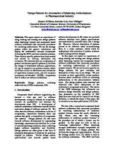
Fig. 3. UML class diagram of the Passive Sensor pattern Behavior: Figure 4 depicts a UML state diagram template capturing the general behavior of a generic passive sensor. Specifically, the passive sensor sends the environmental value when requested from the computing component. Additionally, the passive sensor provides information about its operational state. A developer instantiates this diagram by modifying the transitions to describe the operations and attributes of elements of the instantiated class diagram.
DetermineOS /^Environment.askEnvValue() /^ComputingComponent. reportOperationalState()
getOperationalState()
Idle
SendValue
getEnvValue()
getValueRequest()
/^ComputingComponent.reportValue()
checkData
WaitDataFromEnv
[min