2010, 12th International Conference on Optimization of Electrical and Electronic Equipment, OPTIM 2010
Hardware implementation of a real-time 3D video acquisition system Istvan Andorko¹, Peter Corcoran¹, Petronel Bigioi¹² National University of Ireland, Galway, Ireland¹; Tessera (Ireland) Ltd.²
[email protected];
[email protected];
[email protected],
[email protected] Abstract-An implementation of a real-time 3D video acquisition system on a single FPGA is presented. Our approach is based on the use of stereo image sensors and can display real-time 3D video when combined with shutter glasses. The 3D effect is generated based on the parallax of the stereo sensors. An overview of the system architecture is given, including some details of the FPGA implementation of actual image processing pipeline. This architecture provides the basis for a low-cost, personal 3D imaging appliance. Index Terms – 3D video, stereo imaging, VLSI
I.
INTRODUCTION
Although 3D imaging and video has been around for a few decades, it is only recently that has become known in the movie and home entertainment industry. The first 3D movies have appeared in the 60’s [1] but they were available only in a few selected theaters and the quality of the images was poor. The idea was to have two images with a small horizontal offset between them with one of the images containing only the red component of the image and the other only the blue component. To view these images, anaglyph glasses were used but often these glasses were causing headache or discomfort to the viewers. Current 3D technology is based on the same idea of image parallax, but the technologies and tools available nowadays help us create and deliver higher quality 3D images and video to consumers. Some of these technologies are based on high resolution wafer-level cameras, high refresh rate monitors, used in combination with wireless shutter glasses, Commercial flat-screen TVs incorporating such technology are now available. However the emerging consumer technologies do not provide for consumers to generate their own 3D content. Given the recent growth in popularity of amateur video content as evidenced by www.youtube.com and other content hosting websites it is clear that consumers are no longer simply content to passively absorb content from Hollywood. In this context we anticipate a growing demand from consumers to be able to make their own 3D videos and share this content. Against this background our research seeks to commoditize 3D imaging by exploring the potential of a SoC stereoscopic image processing system. The most important element in the 3D image generation from a pair of stereo images is to have the two image processing pipelines (IPP) which are perfectly synchronized. If this is not possible, slight differences in the two images can
978-1-4244-7020-4/10/$26.00 '2010 IEEE
significantly affect the perceived quality of the 3D image or video.
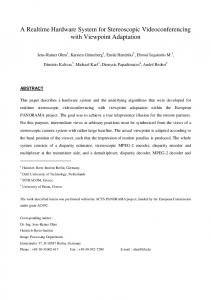
Fig.1. Image processing pipeline
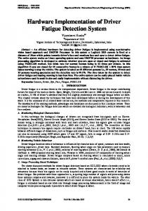
The 3D effect is based in the parallax effect that the stereo images create. Parallax is an apparent displacement or difference of orientation of an object viewed along two different lines of sight, and is measured by the angle or semiangle of inclination between those two lines. The idea is that the human eyes see the objects from two different perspectives and this is how the brain creates the depth effect. Thus, if we feed two images with a slight horizontal offset independently to the left and right eye, we can create the same depth effect. During the early days of the 3D technology this was achieved with the help of anaglyph glasses. These glasses had two different lenses. One of them was red and it allowed only the R (Red) component of the image to go through and the other one was blue or cyan, which allowed only the B (Blue) or B + G (Blue and Green) component of the image to go through. The display of the images had to be adjusted in a similar way. Both images were displayed overlapped, but the left image had only the red component and the right image had only the blue or cyan component.
Fig.2. Example of an anaglyph image [2]
Modern techniques employ a different approach. The corresponding left and right images are sent to the left and right eye independently. On a display source, there are a
920
number of ways to achieve this [3]. The first is the use of auto-stereoscopic display systems that do not require special glasses. The downside of this is that there are only a few viewing angles from which the 3D images can be seen properly. This type of devices also reduces the resolution of the image. A more detailed presentation is given in section II below. A second approach is to use display monitors with a high refresh rate (equal to or higher than 120 Hz) and special shutter glasses. The monitor displays the left and right images frame by frame, alternating between them and the shutter glasses are synchronized with these frames so that the user will see the image corresponding to his left or right eye. Again this is detailed in section II. Our paper presents an implementation of a 3D video acquisition device on a single Virtex4 FPGA, using the Xilinx ML405 development board. Other components of our system are a pair of 1 megapixel CMOS stereo image sensors mounted on a PCB board. Image output can be presented on a standard VGA monitor for test and prototyping of the system. (For demonstration purposes a more sophisticated flat-screen display can be used but this is not practical for day-to-day development activities.) This paper has five main sections. In section II we present a literature review and discuss existing research in this field and the progress of 3D technology since the 1960s. In section III we present our approach and technical details of a preliminary implementation of our dual IPP FPGA system. In section IV several real-time experiments are described to verify and test the functionality of our system. Finally we summarize our progress to date and present some of the work which is still needed to realize our original vision of a handheld stereo imaging appliance. II.
LITERATURE AND TECHNOLOGY REVIEW
A. Acquisition Techniques There are two main parts in the 3D video and image acquisition. The first one is the capturing of the image and the second one is the post-processing [4]. Usually, the acquisition is made by using 2 or 3 camera systems. These cameras need to be perfectly synchronized, otherwise the 3D effect could be lost, or artifacts could appear in the images. Sometimes depth sensors are used together with single image sensors that can be used for 2D to 3D conversion [5], but this practice is used mostly in 3D video acquisition and it’s not always the best approach to create high quality videos. When we are talking about 3D image acquisition, we need to consider the transmission and storage of this data as well. In the same time, we need to develop such systems, that will not require considerable investments from the TV operators to implement and that will comply with the newly developed standards in this area. First of all, we need to consider the encoding of the data. A couple of the well known techniques are MPEG2 and H.264. In addition to these, there are nine choices for spatial resolution, six choices for frame rates, two aspect ratios and either progressive or interlaced scanning [6].
The transmission of the 3D data can be done in two ways. The first would be to use the available coding standards and try to pack the left and right images into a single frame or stream. The second one would be to use AVC multiview coding standard that is optimized for the carriage of stereoscopic signals, but this one would need significant investment in the current infrastructure. Some of the possible frame-packages can be side-by-side, top-bottom, lineinterleaved, frame-interleaved, column-interleaved, checkerboard-interleaved, etc [6]. B. Display Techniques The most important requirement of a 3D display is to create the illusion of depth or distance by using a series of depth cues such a disparity, motion parallax and ocular accommodation [1, 7]. A large number of display techniques have been used over the years and each of them had its positive and negative sides. 3D image display techniques can be divided into two categories: stereoscopic displays and autostereoscopic displays. One of the first versions of 3D display was the anaglyph or color multiplexing technique which used color filtering glasses and this way it was able to redirect the left and right acquired images to the left and right eyes accordingly [7]. This can be included to the stereoscopic category because it was using additional devices, like the anaglyph glasses, to create the 3D effect. We can consider the technique that uses shutter glasses to be part of the same category, and it’s important to specify that the current trend in the 3D home entertainment technology is the use of shutter glasses. The second category, the autostereoscopic device, is also called the true 3D display and advances along three general approaches: volumetric displays, electronic holography and direction-multiplexed displays [3]. In the case of the autostereoscopic device, each eye needs to see the corresponding left or right image. There are a number of viewing zones for these images, this means that the 3D image can be seen only from a certain number of angles. Another problem with this type of device is that with the increase of the number of angles, the horizontal resolution decreases. Our approach is based on the recent development of the DMD (Digital Micromirror Device) which allows a monitor refresh rate of up to 120 Hz [8]. These kinds of monitors, combined with a pair of shutter glasses can provide the best solution for the 3D imaging in home entertainment. III.
OUR APPROACH AND IMPLEMENTATION
This section describes the general architecture of a stereo image acquisition system followed by the architecture of the 3D image acquisition and display system and implementation considerations. A. General Architecture of the Virtex-4 family FPGAs The Virtex4-FX FPGA that we are using offers highperformance, full-featured solutions for embedded platform applications. The device is produced on state-of-the-art 90 nm
921
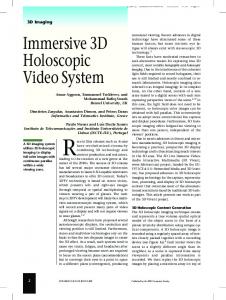
copper process using 300 mm wafer technology. One of its most important features and the reason that makes this device suitable for our application is that is has an embedded IBM PowerPC RISC processor. Some of the most important characteristics of this processor are the up to 450 MHz operation, the 5-stage pipeline and the interface to the Processor Local Bus (PLB) and Device Control Register (DCR). The PLB is a 128-bit bus and it provides infrastructure for connecting an optional number of masters and slaves into an overall PLB system. The DCR is a 32-bit device which is a soft IP core designed for Xilinx FPGAs. It provides support for the communication between the PowerPC microprocessor and the custom IP. Both the PLB and DCR can be instantiated using the Xilinx Platform Studio development software [9]. B. Hardware architecture of the stereo imaging system The general architecture of the system is illustrated in figure 3 below. Note that the use of independent external imaging sensors enables greater flexibility in deciding their relative positioning and also enables the use of twin sensors with differing capabilities, e.g. one wide angle sensor, combined with a normal field of view sensor. While we will not explore such heterogeneous imaging in this paper it is worthwhile noting that it is possible with our system. Indeed the FPGA implementation presented here is designed as a generic SoC platform for dual image enhancement techniques to be explored. In this paper, however, we focus on its applicability to stereoscopic imaging.
Fig.3. General Architecture
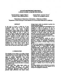
The internal architecture of the design is detailed in figure 4. The main image data is carried over the PLB while control signals are passed between the subsystems over the DCR bus [9].
Fig.4. Internal FPGA Architecture
The development board is a Xilinx ML405 development board, with a Virtex 4 FPGA, a 64 MB DDR SDRAM memory. This FPGA architecture also incorporates a full
PowerPC RISC processor in hardware. The chosen clock frequency of the design is 100 MHz. The sensors used are 1/3 inch SXGA CMOS sensors made by Micron. They have an active zone of 1280x1024 pixels and are programmable through an I2C interface. The sensor is clocked at a frequency of 25 MHz [10]. This sensor was selected because of its small size, low cost and the imaging capabilities are matched to the memory size and processing bandwidth of the Virtex 4 FPGA. The conversion blocks do primary color conversion which consists of gamma correction, demosaicking and other elements of the general image processing pipeline [11]. The camera unit requires a 25 MHz clock signal which is derived from the 100 MHz clock signal of the main FPGA system. . It generates the request signals for the PLB arbiter and generates the addresses for the DDR SDRAM. The PLB is clocked on 100 MHz and it is used for data transfers between the Camera Unit and VGA Controller and the SDRAM memory. The DCR bus is clocked at 100 MHz and is used for communication between the modules in the hardware design and the PowerPC RISC microprocessor. The I2C controller is driven by the PowerPC and allows the configuration of the CMOS image sensors. This system provides an enabling platform for real-time stereo video capture at a standard VGA resolution of 640x480 with a fixed distance between the two imaging sensors. C. Operational aspects of the system The first operation that is executed by the system is the configuration of the working parameters of the sensors using the I2C controller and the I2C bus. The resolution of the sensors is set to 640x480 as this reduces the raw data generated by the imaging sensor and facilitates a real-time implementation. After this step, data is sent to the Camera Unit, which bundles the data into 64 bit registers and requests access to the PLB which directly connects the camera unit to the DDR SDRAM memory. Certain parameters of the camera unit are controlled from the PowerPC through the DCR bus. These parameters include the enabling or disabling of the camera modules, the image downscaling ratio and the memory write start address. Because there are two distinct acquisition chains, an arbitration module is required. This controls access to the PLB bus, allowing only one imaging pipeline to connect at a time. For stereo applications it is sufficient to employ a Round-Robin algorithm for the arbitration module. The same PLB bus is also used for the connection between the VGA Controller and the DDR SDRAM. In the same way the VGA Controller generates the addresses from which the data is being read and it then reads the data from the DDR SDRAM, unbundling a 64 bit register into individual 8 bit registers for the R, G and B color components. In a similar way with the Camera Unit, the VGA controller has a round-robin type of arbitration as well. The read addresses are selected in a round-robin manner. It then generates the synchronization
922
signals and sends the data to the monitor together with these synchronization signals [12]. As for the camera unit, certain parameters of the VGA controller are controlled from the PowerPC microprocessor through the DCR bus. These parameters are the size of the display window and the read start address of the memory. The I2C controller is controlled by the PowerPC microprocessor. The I2C protocol [13] is implemented in the PowerPC in C programming language. The role of the hardware implemented I2C controller is to send the control signals to both sensors one at the time or simultaneously. This allows us to have different configurations for the sensors. The sensors are programmed at the startup of the system. After this, they can be programmed to change based on the user’s preferences. D. Capturing 3D images When using two sensors for stereo imaging, the problem of parallax effect appears, figure 5. Parallax is an apparent displacement or difference of orientation of an object viewed along two different lines of sight, and is measured by the angle of inclination between those two lines.
Fig.6. The DLP 3-D HDTV Video Format
These images can then be viewed using a television with DLP 3-D technology. This technology utilizes the SmoothPictureTM subframes to generate independent views for the left and right eyes. A signal is generated for each subframe and transmitted optically to the LCD shutter glasses that are worn by the viewer. These glasses will process the signal and will control the shutter so that correct left and right views are displayed to the correct eye. In this case the display monitor has a refresh frequency of 120 Hz so the frames appear independently to each eye at a frequency of 60 Hz. The other format which was implemented on the FPGA is based on alternating the views that are being displayed. The left and right images are stored separately and on every vertical synchronization signal, one of these images is displayed. For viewing this format, the user needs special shutter glasses that are synchronized with the vertical synchronization signals of the display controller. This display format can be seen in figure 7.
Fig.5. The parallax effect
Based on this parallax effect it is possible for our brain to generate the depth of the images that we see and to enable us to perceive objects in 3D. Thus by mimicking this effect with our camera system and presenting the captured image sequences using an appropriate display mechanism it is possible for us to capture and store 3D representative images. If these are now presented in the appropriate way our brain will do the real work of making them appear to be genuine 3D representations of the original image scene. As an example of such a display/presentation system there is a new emerging technology for 3D TV. It is based on the DLP 3-D HDTV technology and there are a few companies that already manufacture 3D-ready TVs. The DLP 3-D image makes use of how the DLP SmoothPictureTM algorithm displays an image onto the screen. The left and right images are sampled using the native offset diagonal sampling format of the DMD (Digital Micro-mirror Device). The two views are then overlaid and appear as a left and right checkerboard pattern in a conventional orthogonal sampled image [14], figure 6.
Fig.7. The interlaced layer format
The proper viewing of the images in 3D is based on the proper alignment of the input images and on the synchronous reading from the sensors. The average human eyes are at a distance of 84 mm from each other. To be able to see the 3D images, it is advised that the distance between the sensors is of 84 mm +/- 5 mm. The vertical alignment of the images pair is of a great importance as well. For best viewing, the lines from the two images should be epipolar [15]. In practice it is
923
very difficult to set up a pair of sensors so that the lines from the images are on epipolar lines. Fortunately, the human eye has the capability to correct for miss-aligned stereoscopic pictures. If the sensors were not synchronous in their operation the corresponding frame would not arrive at the same time which would lead to a poor viewing quality for the 3D images. IV.
Figure 10 represents the timing report for our IP. This report shows the maximum frequency at which the IP can work, based on the delays introduced by the system design. Since the value of the maximum frequency meets our initial design specifications we didn’t need to do any improvements. One way to improve this would have been to analyze the timing reports on each of the modules separately and to implement pipelining at the places with a bottleneck.
TESTING THE SYSTEM AND EXPERIMENTS
A. Simulation, Device Utilization and Timing reports of the Verilog design For the testing and simulation of the design, a Modelsim PE 6.3 hardware simulation software has been used. Instead of the CMOS sensor, a VerilogHDL model of the MT9M011 sensor has been used that simulates the functionality or the real sensor, and which had as an input a RAW image. This way, the VerilogHDL model of the sensor was able to feed RAW images in Bayer format to the design. To be sure that everything was working right, dump of data had to be made. This meant that data was written into text files after each processing block and by converting the data from the text files into images, we were able to check that the processing was done properly. Figure 8 represents the architecture of the testing system using the simulation software.
Fig.8. Architecture of Testing System for Dual Sensor Design
For the testing of the design in real-time, a Xilinx ML405 development board, two MT9M011 CMOS sensors and a CRT monitor had been used. The test proved the proper functionality of the system. For the interconnection of the different modules in the system, Xilinx Platform Studio development software has been used. It has generated the following reports about our IP. The device utilization report, which indicates how much space of the FPGA our IP occupies, figure 9.
Fig.10. Timing Report
B. Practical Problems: EM Incompatibility Problem For the testing of the synchronised operation of the sensors, a test design was originally developed, where both sensors used the same incoming synchronization signal. This was observed to cause a physical shift between the left and right images. After some analysis and further testing it was determined that this is an Electromagnetic interference (EMI) problem. Example images are shown in figure 11.a. where you can clearly see from the right-hand picture that the frame is shifted significantly to the right. This EMI problem was solved by rebuilding the connections between the sensors and the board, in particular making the connections shorter, and connecting the analogue ground pin in the close vicinity of the Vcc pin. Example images can be found in figure 11.b. where you can clearly see that the frames are at the same position and this problem has been solved. It is worth remarking that the image-offsetting effect of this EMI phenomenon is quite confusing and our initial investigations were directed to determine if some spatial, optical or timing errors were the root cause. In the end it turned out that it was the signal interconnections which were at fault due to the relatively high frequencies involved. We include this discussion so other researchers can avoid our confusion as to the cause of this phenomenon.
Fig.11.a. Electromagnetic Incompatibility Problem
Fig.9. Device Utilization Report
924
[3]
Fig.11.b. The EMI problem is solved
C. Testing of the 3D imaging system For the testing of the system a pair of stereo images were used, which were taken with two Samsung NV9 digital cameras which were placed on the same tripod. The pictures were taken in the same time with similar settings. The distance between the two lenses was around 100 mm. These pictures were applied as an input to our design at simulation. The outcome of the simulation can be viewed in figure 12.
Fig. 12. From left to right, zoomed in left image, zoomed in right image and final image
For the real-time testing of the design, a Xilinx ML405 development board with a Virtex 4 FPGA has been used. The sensors are 1 megapixel MT9M011 CMOS sensors manufactured by Micron. For the display of the image a normal CRT monitor has been used, with a VGA input. The resolution of the output image is 640x480. One technical difficulty that we encountered was that the resolution requirement for these televisions is either 1280x720 or 1920x1080. For these resolutions a large bandwidth is required. Our design was built to work on a 640x480 resolution, but we are confident that by attaching better sensors and optimizing the design, we will manage to provide the appropriate throughput.
Y. Zhu and T. Zhen, “3D Multi-view autostereoscopic display and its key technology”, Asia-Pacific Conference on Information Processing, pp. 31-35, 2009. [4] P. Merkle, K. Muller and T. Wiegand, “3D Video: Acquisition, Coding and Display” Digest of Technical Papers, IEEE International Conference on Consumer Electronics, pp. 127-128, January 2010. [5] M. T. Pourazad, P. Nasiopoulos and R. K. Ward, “An H.264-based scheme for 2D to 3D video conversion”, IEEE Transactions on Consumer Electronics, Vol. 55, No.2 pp.742-748, May 2009. [6] D. K. Broberg, “Considerations for stereoscopic 3D video delivery on cable”, Digest of Technical Papers, IEEE International Conference on Consumer Electronics, pp. 129-130, January 2010. [7] L. M. J. Meesters, W. A. Ijsselsteijn and P. J. H. Seuntiens, “A survey of perceptual evaluations and requirements of three-dimensional TV”, IEEE Transactions on Circuits and Systems for Video Technology, Vol.14, No.3, pp.381-391, March 2004. [8] D. C. Hutchison, H. W. Neal, “The design and implementation of a stereoscopic microdisplay television”, IEEE Transactions on Consumer Electronics, vol. 54, no.2, pp. 254-261, May, 2008. [9] All the information can be found on www.xilinx.com [10] www.datasheetcatalog.com/ datasheets_pdf/m/t/9/m/mt9m011.shtml [11] W. C. Kao, S. H. Wang, L. Y. Chen and S. Y. Lin, “Design considerations of color image processing pipeline for digital cameras”, IEEE Transactions on Consumer Electronics, vol. 54, no. 4, pp. 11441152. November, 2006. [12] D. Vanden Bout, “VGA Signal Generation with the XS board”, Application Note, August 1998. [13] www.esacademy.com [14] http://dlp.com/hdtv/3-d_dlp_hdtv.aspx [15] M. Zhu, Y. Ge, S. Huang and W. Chen, “Stereo vision rectification based on epipolar lines match and three variables projective matrix”, IEEE International Conference on Integration Technology, 2007. [16] M. W. Stockfish, “Prospective standards for in-home 3D entertainment products”, Digest of Technical Papers, IEEE International Conference on Consumer Electronics, pp. 133-134, January, 2010.
CONCLUSIONS AND FUTURE WORK
We developed a Stereo Imaging system based on a single FPGA which is suitable for capturing 3D images. Due to its small size, the design could be used for small handheld devices to acquire HD 3D images that can be replayed on state-of-the-art home entertainment systems. Regarding our future work, we are planning to make this design work with higher resolution, better quality image sensors and make the acquiring, transmission and display of the 3D images available based on the current standards [16]. ACKNOWLEDGMENT The project is financed by the Irish Research Council for Science, Engineering and Technology (IRCSET) and Tessera (Ireland). REFERENCES [1] [2]
L. Onural, T. Sikora, J. Ostermann, A. Smolic, M. R. Ciyanlar and J. Watson, “ NAB Broadcast Engineering Conference, 2006. apod.nasa.gov/apod/ap080706.html.
925