Hardware Implementation of a Visual-Motion Pixel Using ... - CiteSeerX
Recommend Documents
Feb 1, 2013 - Sonjoy Deb Roy, Xin Li, Yonatan Shoshan, Alexander Fish, Member, ...... [39] G. Petitjean, J. L. Dugelay, S. Gabriele, C. Rey, and J. Nicolai, ...
Nov 1, 2005 - Shehzad Khan. University of Pennsylvania. Jan Van der Spiegel. University of Pennsylvania, [email protected]. Paul Mueller. Corticon, Inc.
This paper presents a reformulation of the Phong shading algorithm, that is .....
The reason of using the square of the cosine function is that Т is greater than 2 in.
In this paper all digital encryption techniques were tested on three multimedia items: (i) machine written English text; (ii) two seconds length mono-type audio, ...
Department of Electronic Engineering, National University of Ireland, Galway. Tel: +353-91-524411, Fax: 750511. E-mail: [email protected]. Abstract.
This paper describes an FPGA and distributed RAM architecture for an image pixel processor implementing .... 4.1 FPGA Technology and RAM bandwidth .... and pipeline execution of the basic quad pixel based processing (i.e. subtraction,.
performance with existing DSP processor-based alternatives is detailed. ... FPGA, Virtex, RC1000-PP, Handel-C, Object Detection, Image Processing. 1.
[6] M.Smith, I.Posner and Paul Newman. Adaptive compression for 3D laser dataâ The International Journal of Robotics Research. 30,7, (2011) 914â935.
Sep 2, 2010 - capabilities [4]. However, their proposed digital system as a hardware implementation of IDS method [4] or the one suggested by Tarkhan et al.
We express our gratitude to Hans Peter Graf for his ... 2] E. Sackinger, B.E. Boser, J. Bromley, Y. LeCun ... 11] Patrice Y. Simard and Hans Peter Graf \Back-.
A Hardware Triple-DES cryptographic algorithm has been implemented ... digital cryptographic circuit, which was implemented in a FPGA chip with the use of ...
A database containing these feature vectors can be constructed, allowing query vectors to ... by using FPGA based hardware IP cores and compares this to a software .... devices i.e. to take advantage of the hardwired MAC cells in this FPGA.
col specifications modeled by concurrent EFSMs with multi-way synchronization into ... switches, we have confirmed that hardware circuits synthesized with the ...
than the conventional trellis typically used to construct Viterbi decoders. The authors state .... achieving the same performance in terms of bit error rate. (BER).
Because the implementation is pipelined (flip-flops are added after each processing ... Notice that the output does not hold a flip-flop; so this block does not ...
speed and smaller size for real time application than the VLSI design. In ... introduction of FPGAs, it is feasible to provide custom hardware for application.
Dividend
widely used. First, the complete system must be affordable. .... The genetic algorithm (GA) is an optimization tool, using ... Compared to traditional search meth-.
{cesar, amt}@ohm.york.ac.uk. Abstract. This paper presents a ... The embryonics project transports these biological mechanisms to the world of electronic ... select a new configuration register from their memory (genome). By selecting a new.
Java programs are designed to run on the virtual platform instead of being directly executed on the host processor. This achieves the goal of âwrite once, execute ...
on a single processor which makes the overall hardware-software system design ..... We call such an implementation of a loop construct in software a pseudo-static ..... MIP 9115432 and by a fellowship provided by the Center for Integrated ...
system model under input/output data rate constraints in [1]. In this paper we .... The following lists the relevant assumptions relating to target architecture. We restrict .... Therefore, for a given re-programmable device the bound on latency of .
The Java Virtual Machine (JavaVM) has contributed greatly to Java's ... the SPARC and PowerPC architectures), SGI (MIPS RISC) and Microsoft,. Netscape ...
a software implementation on a general-purpose net- .... through with a write bu er connecting it to main ... caches, and a write bu er from the primary cache to.
Hardware Implementation of a Visual-Motion Pixel Using ... - CiteSeerX
Copyright 1999 IEEE. Reprinted from IEEE Transactions on Circuits and Systems — II: Analog and Digital Signal Processing. Volume 46, Issue 9, September 1999, pages 1121 - 1136. This material is posted here with permission of the IEEE. Such permission of the IEEE does not in any way imply IEEE endorsement of any of the University of Pennsylvania's products or services. Internal or personal use of this material is permitted. However, permission to reprint/republish this material for advertising or promotional purposes or for creating new collective works for resale or redistribution must be obtained from the IEEE by writing to [email protected]. By choosing to view this document, you agree to all provisions of the copyright laws protecting it. This paper is posted at ScholarlyCommons. http://repository.upenn.edu/ese_papers/140 For more information, please contact [email protected].
IEEE TRANSACTIONS ON CIRCUITS AND SYSTEMS—II: ANALOG AND DIGITAL SIGNAL PROCESSING, VOL. 46, NO. 9, SEPTEMBER 1999
1121
Hardware Implementation of a Visual-Motion Pixel Using Oriented Spatiotemporal Neural Filters Ralph Etienne-Cummings, Member, IEEE, Jan Van der Spiegel, Senior Member, IEEE, and Paul Mueller
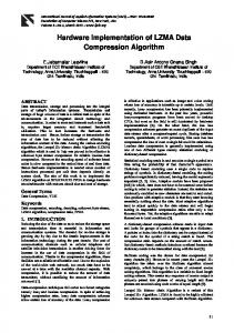
Abstract— A pixel for measuring two-dimensional (2-D) visual motion with two one-dimensional (1-D) detectors has been implemented in very large scale integration. Based on the spatiotemporal feature extraction model of Adelson and Bergen, the pixel is realized using a general-purpose analog neural computer and a silicon retina. Because the neural computer only offers sum-and-threshold neurons, the Adelson and Bergen’s model is modified. The quadratic nonlinearity is replaced with a fullwave rectification, while the contrast normalization is replaced with edge detection and thresholding. Motion is extracted in two dimensions by using two 1-D detectors with spatial smoothing orthogonal to the direction of motion. Analysis shows that our pixel, although it has some limitations, has much lower hardware complexity compared to the full 2-D model. It also produces more accurate results and has a reduced aperture problem compared to the two 1-D model with no smoothing. Real-time velocity is and 18 represented as a distribution of activity of the 18 velocity-tuned neural filters.
X
Y
Index Terms—Vision chips, visual motion detection, VLSI neural filters.
I. INTRODUCTION
T
HE VISUAL-motion detection mechanism employed by insects, such as flies, and primates are quite different. The effective computations performed by these organizms, however, have been shown to be identical [1], [2]. For insects, motion estimation is performed very early, immediately following the light-sensitive omatidia, while for primates, the motion center is area medial temporal (MT) in the cortex [3], [4]. As a result, the fly’s motion-detection neural circuits can be modeled with mostly nearest neighbor correlation of the omatidia outputs to extract both direction and speed of moving light patches. There are obvious survival benefits for the early implementation of visual motion detection in flies. Hence, the insect visual motion neural networks are designed to optimally match the expected spatiotemporal characteristics of the environment in which they live, and are consequently narrowband and velocity-specific detectors. For primates, on the other hand, the visual tasks required for survival are much more complex. The environment in which primates live has a wide range of spatiotemporal frequencies, and motion Manuscript received July 23, 1998; revised June 4, 1999. This paper was recommended by Associate Editor P. Thiran. R. Etienne-Cummings is with the Department of Electrical and Computer Engineering, Johns Hopkins University, Baltimore, MD 21218 USA. J. Van der Spiegel is with the Moore School of Electrical Engineering, Center for Sensor Technologies, University of Pennsylvania, Philadelphia, PA 19104 USA. P. Mueller is with Corticon, Inc., Philadelphia, PA 19104 USA. Publisher Item Identifier S 1057-7130(99)08039-8.
estimation must be performed on targets with a wide velocity dynamic range. Since primates are visual animals, a large portion of the cortex is dedicated to visual processing, which is also integrated with other sensing, reasoning and behavioral centers of the brain. Consequently, the method employed for primate visual-motion estimation exploits the availability of a large amount of wetware to realize robust, wide dynamic range, general-purpose motion-estimation circuits. Attempts to implement visual-motion estimation in VLSI hardware have followed the fly’s model [5], [6]. This has been influenced strongly by the limited space and power available to realize focal-plane motion detection circuits which can be easily integrated on behaving systems such as robots, autonomous vehicles, and gaze controllers. Consequently, the last few years have produced some elegant focal-plane motion detection circuits based on the fly’s model, while expanding its spatiotemporal bandwidth and dynamic range [6]–[9]. The approach presented here is not a competitor for these compact focal-plane solutions. Our method requires too much hardware for focal-plane implementation. It is, however, intended for the scenario where a functional “silicon cortex,” with many neurons, synapses, and axon/dendrites, is available and applied to a problem requiring visual motion as a prerequisite. In this paradigm, the motion-detection mechanism must be compatible with the other computations performed by the “silicon cortex.” Hence, the implementation presented here mimics the physical organization of the primate visual system, and the computation model for cortical visual-motion estimation. Visual-motion estimation is an area where spatiotemporal computation is of fundamental importance. Each distinct motion vector traces a unique locus in the space–time domain. Hence, the problem of visual-motion estimation reduces to a feature extraction task, with each feature extractor tuned to a particular motion vector. Since neural networks are particularly efficient feature extractors, they can be used to implement these visual-motion estimators. Such neural circuits have been recorded in area MT of macaque monkeys, where cells are sensitive and selective to two-dimensional (2-D) velocity [4]. Here, a hardware pixel for two 1-D visual-motion estimation with spatiotemporal feature extractors is presented. A silicon retina with parallel continuous-time edge-detection capabilities is the front-end of the system. Motion detection neural networks are implemented on a general-purpose analog neural computer, which is composed of programmable analog neurons, synapses, axon/dendrites, and synaptic time constants [12]. The additional computational freedom introduced by the synaptic time-constants is required to realize
1057–7130/99$10.00 1999 IEEE
1122
IEEE TRANSACTIONS ON CIRCUITS AND SYSTEMS—II: ANALOG AND DIGITAL SIGNAL PROCESSING, VOL. 46, NO. 9, SEPTEMBER 1999
(a)
(b)
(c)
Fig. 1. (a) 1-D motion is orientation in the space–time domain. (b) Motion detection can be realized with oriented spatiotemporal filters. (c) The distribution of the velocity-tuned filter responses encode the stimulus velocity.
the spatiotemporal motion estimators. The motion detection neural circuits are based on the early one-dimensional (1-D) model of Adelson and Bergen and recent 2-D models of David Heeger [1], [10], [11]. Since the neurons only computed delayed weighted sum-and-threshold functions, the models are modified. The original models require a division for intensity normalization and a quadratic nonlinearity to extract spatiotemporal energy. In our model, a silicon retina performs intensity normalization with high contrast sensitivity (a binary edge image is produced), and the quadratic nonlinearity is replaced by rectification. In an effort to handle 2-D motion detection with a tractable hardware complexity, we use smoothing prefilters orthogonal to the direction of motion and two 1-D detectors. We show that this approach reduces the amount of hardware required per pixel considerably, compared to the full 2-D implementation of Heeger, however, it is not as general. Compared to the two 1-D method without prefiltering, our model produces more accurate results and has less of an aperture problem. It does, however, require that the spectral components of the stimuli exist in the - and - planes. If none of the spectral power of the stimulus appears in - and - planes, our approach would produce the no output, while the strict two 1-D approach would produce incorrect results. Fortunately, the binary image produced by the silicon retina places spectral components in these planes for most images (intensity gradients with too small contrast do not produce a binary image). The measured tuning curves of and 18 velocity-selective neural filters are presented. 18 The visual-motion vector is implicitly coded as a distribution of neural activity, and the explicit velocity is computed by the first moment of the distribution. II. THEORY OF SPATIOTEMPORAL FEATURE EXTRACTION AS MOTION DETECTORS
for detecting motion [13]. Fig. 1(a) shows an oriented filter sensitive only to symmetric moving features; an antisymmetric filter is also required. Hence, quadrature pairs of oriented filters at various scales are used to measure visual motion in a realistic scene. In the frequency domain, the motion of a point is also a line. The slope of the line is the velocity of the point. Hence orientation detection filters, shown as circles in Fig. 1(b), are used to measure the point’s velocity relative to their preferred velocity. A population of these tuned filters, Fig. 1(c), can be used to measure general image motion. B. 1-D Oriented Spatiotemporal Filters The construction of the spatiotemporal motion detection units is based on the frequency domain representation of visual motion. In the frequency domain, constant 1-D motion of a point is represented as a line through the origin with a slope where is the velocity, is the is the spatial frequency. That is, temporal frequency, and is . Oriented the Fourier transform of spatiotemporal filters tuned to this velocity can be easily constructed using separable quadrature pairs of spatial and and respectively, where the temporal filters tuned to . The phase relationship preferred velocity between the filters allows them to be combined such that they cancel in opposite quadrants, leaving the desired unseparable oriented filter. Hence, quadrature pairs of oriented filters are created and must be considered together to measure the complete influence of the motion of a general image patch. Fig. 2 shows the construction of oriented filters for 1-D motion. Examples of separable spatial and temporal filters and the constructed motion detectors, employed by Heeger, are given in (1)–(3) [11]. The only requirements for successful candidate functions are that they should be matched, bandlimited and quadrature counterparts. Equation (3) shows how they are combined to realize oriented spatiotemporal filters
A. Overview The technique of estimating motion with spatiotemporal feature extraction emerged from the observation that a point moving with constant velocity traces a line in the space-time domain, as is shown in Fig. 1(a). The slope of the line is proportional to the velocity of the point. Hence, the velocity is represented as the orientation of the line. Spatiotemporal orientation detection units, similar to those proposed by Hubel and Wiesel for spatial orientation detection, can be used
(1a) (1b) (2a) (2b)
ETIENNE-CUMMINGS et al.: HARDWARD IMPLEMENTATION OF A VISUAL MOTION PIXEL
1123
(a)
(a)
(b) Fig. 3. (a) 1-D motion of a point produces a broad distribution of filter responses. (b) Motion of sinusoidal grating produces a narrow distribution of filter responses. The centroid relays the explicit velocity.
filter is subsequently given by (4)
Right
(b) Fig. 2. In the frequency domain, motion filters are constructed with quadrature pairs of oriented spatiotemporal filters. (a) Even-oriented filters. (b) Odd-oriented filters.
Right or Right Left
(3a)
Left
(3b)
or
The complete velocity selective filter is constructed by combining the even and odd oriented filters, i.e., Right Right Right . Since this technique measures the energy of the input signal about the preferred orientation of the filter, it suffers from velocity/contrast ambiguity. That is, a bright object with velocity far from the preferred value may solicit a stronger response than a dim object closer to the preferred value. To eliminate this effect, the output of the velocity sensitive filter is normalized by the contrast of the image patch at the spatial scale of the oriented filter. The final frequency domain response of an oriented motion detection
Left
(4)
is the output energy of the filter and is a bipolar representation of velocity. Because this filter is tuned to a specific velocity at a specific spatiotemporal frequency, the complete model is then composed of a population of similar detectors with various spatiotemporal tuning. The velocity is extracted from the distribution of filter outputs, much like the motion sensitive cells from area MT of macaque monkeys [4], [14], [15]. Fig. 3(a) shows a possible placement of the motion filters - plane. The responses of the filters to a moving in the point are shown in gray scale, where black implies maximum activity. Since the moving point has a flat power spectrum, all filters along its velocity will be stimulated. Hence, a broad distribution of responses is observed. The centroid of the distribution of responses provides an optimal estimate (in the least-squared sense) of the motion, which improves as more filters with more overlapping passbands are used [14]. Other heuristics may be used to extract the explicit velocity. Equation (5) gives the relationship for the estimated velocity, where is the number of oriented filters and ( ) is the tuned velocity for each filter
(5)
1124
IEEE TRANSACTIONS ON CIRCUITS AND SYSTEMS—II: ANALOG AND DIGITAL SIGNAL PROCESSING, VOL. 46, NO. 9, SEPTEMBER 1999
(a)
(b)
(c)
Fig. 4. Measurement of 2-D motion with oriented filters. (a) Single filter responds to a continuum of 2-D motion planes. (b) Two oriented filters isolate the correct motion plane, but do not respond to all spatiotemporal frequencies. (c) A collection of filters isolates the correct motion plane and spans all spatiotemporal frequencies.
In Fig. 3(b), a moving sinusoidal grating is presented as input. The grating’s spectrum is localized at a single point plane. Consequently, the filter responses are in the narrowly distributed about the filter closest in spatiotemporal tuning to the grating. None-the-less, a centroid of the responses provides a good estimate of the grating’s velocity. Grzywacz and Yuille have argued that only two filters are required to estimate the velocity, however, the accuracy of the estimation will decrease as the spatiotemporal spectrum of the image and the oriented filters differ [14]. This is illustrated by the sinusoidal grating stimulus, which produces no filter responses if its spatiotemporal spectrum does not appear within the passband of any of the motion detectors. Clearly, a generalpurpose motion detection system using oriented spatiotemporal filters must cover the entire frequency range of the intended stimulus. A mosaic of individual filters located at various tunings, as shown in Fig. 3, can be used. In addition, this collection of filters must also be replicated at every pixel. Evidently, this approach is hardware implementable only in a large system. C. 2-D Oriented Spatiotemporal Filters ) motion, the problem If the point exhibits 2-D ( is substantially more complicated [11], [15]. A point executing 2-D motion spans a plane in the frequency domain. The approach presented above for constructing oriented filters still applies in two dimensions. The oriented filters of the form in (6), derived from (4), respond not only to the desired motion, but also to a continuum of motion satisfying where and are the velocity components ) is the spatiotemporal defining the plane, and ( tuning of the filter. The filters and in (6) are orthogonal to each other. This is a manifestation of the famous aperture
where
problem, and results from the observation that a single 2-D oriented filter solves one equation of two unknowns. This problem is graphically shown in Fig. 4(a)
(6a)
(6b)
(6c)
(6d) If two sets of oriented filters are used, the correct motion plane can be isolated (i.e., two equations of two unknowns). However, the two filters would only cover the spatiotemporal bands defined by their tuning and bandwidth, as shown in Fig. 4(b). Hence, this configuration is effective only for broadband images. A collection of filters spanning all combinations ) in the plane of the correct motion is then of ( required. Fig. 4(c) shows schematically one such filter tuned to a band of frequencies on the preferred motion plane. To respond to a general image patch at this preferred velocity, a number of these torus-shaped filters, with increasing radii, is required to cover the bandwidth of the image. Equations (7a) and (7b), shown at the bottom of the page, give the expression for one of the torus-shaped filters. The equation assumes that individual filters in the torus are placed such that they overlap
and
(7a) (7b)
ETIENNE-CUMMINGS et al.: HARDWARD IMPLEMENTATION OF A VISUAL MOTION PIXEL
at ( and the centers of the filters are apart, where ( ) are, respectively, the bandwidths of the separable filter components. Hence, filters are required per torus, where is the radius of the th torus, and is the number of individual velocity-tuned filters used to create the torus. The bandwidth of the wideband velocity-tuned filter is the sum of tori as in the bandwidths of the filters ( ) in each of the (7a) and (7b), shown at the bottom of the previous page. The construction of the wideband velocity filter tuned to separable this one motion plane requires a total of spatiotemporal filters per pixel. To cover a large range of speed and direction, many such filters are required. Assuming the velocity planes same coverage strategy as for each torus, separable filters are required, resulting in a total of per pixel. In comparison, for the 1-D case, assuming the same coverage algorithm, the number of separable filters required . (In a sparsely distributed example where is and the number of separable filters required is 5184 per pixel for the full 2-D model, compared to 144 for the two 1-D case.) The speed and direction of a general image patch can be extracted from the distribution of filter responses as given by (8)
1125
(a)
(b)
Fig. 5. (a) Measuring 2-D motion with a 1-D detector is aperture limited and (b) produces errors.
B. Two 1-D Motion Detection Consider a 1-D motion detector for -velocity. It is realized with a row of pixels, and the measured motion is reported at the central pixel. When a 2-D stimulus falls across its receptive field, a single sample of the stimulus is taken in the -direction, and in the -direction, the number of samples corresponds to the spatial scale of the detector. Clearly, the aperture problem in the -direction is more severe than in the -direction for an -velocity detector. Fig. 5(a) shows this process schematically. The velocity reported by an - and -detector pair is given by (9) for a line oriented at to the ) horizontal and moving with velocity ( -
and
-
(9)
and
(8)
Evidently, the hardware complexity for realizing the full 2-D motion detection filters is too large and completely intractable in current very large scale integration (VLSI) systems. Using to two 1-D detectors reduces the complexity for but there are some penalties. Below, we discuss the hazards of measuring 2-D motion with two 1-D detectors. We also propose an approach to reduce the disadvantages. We show that our two 1-D method only approximates 2-D motion detection in special cases. Our system promotes the special cases. III. MEASURING 2-D MOTION WITH TWO 1-D DETECTORS A. Overview Measuring 2-D motion with two 1-D motion detectors is fraught with problems. In special cases, however, the two 1-D detectors do produce the correct 2-D results. First, we present the problems with the two 1-D approach, and subsequently, we identify the cases where it produces the correct results. Lastly, we show how our system promotes the special cases and how it is constructed.
Equation (9) illustrates both the aperture problem and the propensity for two 1-D detectors to provide extremely wrong measurements as the orientation of the 2-D stimulus approaches 0 or 90 On the other hand, if the stimulus is a vertical or a horizontal line, the correct aperture limited measurement is obtained. To understand the impact of a general 2-D image patch on 1-D detectors, the frequency domain analysis is more illuminating. A 1-D -velocity detector is oriented in the plane, but extends infinitely in . The inverse is true for the -velocity detector. Consequently, as shown in Fig. 5(b), the motion of any image patch from a continuum of motion planes matching the passband of the filter will produce an incorrect response. The only correct response is - plane, where produced by the detector located in the - plane. Unfortunately, the motion plane intersects the the latter detector is triggered only if the image patch has spectral components in this plane. Nonetheless, it is better to report zero motion rather than the incorrect velocity. Two 1-D motion detection measures the correct 2-D motion if the passband of the 1-D detectors are restricted to the - and - planes, and if the stimulus has spectral energy in those planes. This implies that the infinite extent of the passband of the 1-D detectors in the direction orthogonal to motion must be suppressed. Furthermore, the image must either already have - and - planes, or must spectral components in the be forced to have so. Our system attempts to realize these two constraints.
1126
IEEE TRANSACTIONS ON CIRCUITS AND SYSTEMS—II: ANALOG AND DIGITAL SIGNAL PROCESSING, VOL. 46, NO. 9, SEPTEMBER 1999
C. Realizing 2-D Motion Estimation with Two 1-D Detectors To restrict the frequency response of the 1-D motion de- and - planes, a smoothing prefilter tectors to the is applied in the direction orthogonal to motion. If the prefilter has infinite spatial scale, this is identically realized. In our system, an approximation is obtained with a smoothing “Gaussian” filter with twice the spatial scale (15 pixels) of the largest scale motion filter (7 pixels). An approximation of a Gaussian prefilter is chosen to reduce the high frequency side-lobes of the smoothing filter. Furthermore, smoothing at a larger scale than the motion detection and using a tapered smoothing kernel suppress edge effects.1 Moreover, the receptive field of the 1-D detector is widened in the smoothing direction. Consequently, the aperture problem is reduced in our model compared to the two 1-D case without prefiltering, however, motion blurring across object boundaries will be more prevalent. The two 1-D images that are produced are used as inputs for the 1-D detectors. The power spectrum of the image must exist in the – , – planes for the two 1-D detectors to measure and 2-D motion, albeit aperture limited. For wideband images, such as points, lines or abrupt edges, the power spectrum already exists in these planes. In these cases, other than the aperture limitations, the two 1-D detectors produce the correct – and 2-D results if the detectors are limited to the – planes. For a narrow-band image, such as a sinusoidal gratings and plaids, there are no spectral components in these planes. Here, our 2-by-1-D detectors would produce no results, while the version without prefiltering would produce incorrect results. Our system, however, goes one step further and places some spectral components in the - and planes. This is performed by the silicon retina front end, which converts all images to binary images of edges. The sinusoidal plaid is thus converted into a square plaid, which is a wideband image. The additional benefit of the silicon retina is outlined below. Equation (10) outlines, mathematically, how the two components of motion can be extracted. Fig. 6 shows schematically how correct 2-D motion can be extracted with the two orthogonal sets of 1-D oriented filters
(10a)
(10b) D. Modified Two 1-D Construction In addition to the modifications mentioned above, there are two further changes required for implementing oriented spatiotemporal filters with a relatively small number of analog neurons, synapses, axons/dendrites, and synaptic time constants. The first modification handles the need for contrast normalization. In Section II-A, we argued that contrast 1 An oriented line that extends beyond the smoothing window moving in the direction orthogonal to the 1-D detector will produce and error similar to (9) unless these edge pixels are suppressed.
(a)
(b) Fig. 6. (a) 2-D motion detection with two 1-D filters isolated to the !x -!t and !y -!t planes produce correct results. (b) The oriented filters are organized in the !x –!t and !y –!t planes for wideband wide-range velocity detection.
normalization was required to remove the speed-contrast ambiguity. This is realized by dividing the filter response by the magnitude of the spatial contrast falling within its receptivefield. Unfortunately, ratios can not be easily implemented with linear sum-and-threshold neurons. We eliminate the need for contrast normalization by performing edge detection and labeling before motion detection. That is, a silicon retina is used to image the scene, to compute, in parallel, a 2-D convolution of the image with a band-limited Laplacian operator and to form a binary image of edges [6], [16]. The binary image is realized by thresholding the positive lobe of the ) to the maximum voltage. This process has edges ( the effects of creating a spatiotemporally robust wideband image of strong edges with identical contrast. Furthermore, this procedure removes the potential singularity in (4) and (7) for noisy and low contrast images. This is equivalent to incorporating a confidence measure, as proposed by Uras et al., when reporting visual-motion measurements [17]. Here we measure the motion of robust edges, which produce high confidence results. Fig. 7 shows a block diagram of the silicon retina. The second modification is to replace the quadratic nonlinearity with a full-wave rectification. In Sections II-B and II-C, the filter response is squared to extract its energy content. This has the additional feature of rectifying the response. Since multiplication is also hard to realize with simple linear sum-and-threshold neural networks, the squaring operation is replaced by a full-wave rectification. In this case, the output of the filter is the square-root of the energy. Full-wave
ETIENNE-CUMMINGS et al.: HARDWARD IMPLEMENTATION OF A VISUAL MOTION PIXEL
1127
Fig. 7. The block diagram of silicon retina.
rectification can be easily implemented with half-wave rectified linear neurons. In our system, each 1-D oriented filter is given by Right Right
Right
(11a)
Left Left
Left
(11b)
Right
Left
(11c)
IV. CONSTRUCTING THE SPATIOTEMPORAL MOTION FILTERS
Fig. 8. Spatial presmoothing orthogonal to the direction of motion produces two 1-D images.
B. Spatial Prefiltering Section III indicates that a smoothing prefilter is required to eliminate frequency components in the spatial direction orthogonal to the 1-D motion filters (see fig. 8). The scale of the prefilter is set to provide a good approximation of a delta function in the frequency domain, while not over smoothing the image. Clearly, as the scale of the smoothing filter increases, multiple independent objects can be combined. The measured motion will then be the average motion in the pixel’s receptive field. An approximation of a Gaussian [1, 0.97, 0.9, 0.8, low-pass filter of 15 pixels, half kernel 0.6, 0.35, 0.05, 0.01], is used since the motion detector is 7 image pixels. constructed of 7
A. Overview
C. Spatial Filters
Two 1-D motion detection can be used to approximate the full 2-D model with a much reduced hardware complexity per pixel. Section II-B outlines the steps for creating oriented filters tuned to 1-D motion. Coupled with the preconditioning of the image, using the silicon retina and the smoothing prefilters, the two 1-D detectors are realized with and directions, two 1-D sets of filters tuned to the respectively. Quadrature pairs of spatial and temporal filters are required to construct the oriented filters. The spatial and temporal filters are used to realize the separable spatiotemporal filters that are not velocity selective. Due to their independence and separability, the velocity nonselective spatiotemporal filters are obtained simply by cascading the spatial and temporal filters. The individual spatial and temporal filters have narrow bandwidths, hence a number of these filters are required to cover the expected bandwidth of the input image. Here, three spatial and three temporal quadrature pairs are used, resulting in 36 velocity nonselective filters. Using these velocity nonselective separable filters, 18 oriented velocity selective nonseparable spatiotemporal filters are created. These 18 filters are composed of nine pairs tuned to the same spatiotemporal frequency and speed, but opposite directions.
The chosen spatial filters quadrature pairs are discrete approximations of first- and second-order derivatives of Gaussian functions. The first-order derivative provides an odd function, while the second-order derivative provides an even function. The space constant of the filter pair is set by the number of pixels used. That is, the spatial extent of the filter will be three pixels for the highest frequency filters and seven pixels for the lowest frequency filters. The sums of the positive and negative coefficients are 0.5 and 0.5, respectively, for all scales. Table I shows the coefficients used to implement the three scales of the spatial filter pairs. Equation (12) gives the is general expression for filters in frequency space, where the number of coefficients in the half kernel. Equation (13) . This is also repeated in the gives the expression for -direction (12a) (12b) (13a) (13b)
1128
IEEE TRANSACTIONS ON CIRCUITS AND SYSTEMS—II: ANALOG AND DIGITAL SIGNAL PROCESSING, VOL. 46, NO. 9, SEPTEMBER 1999
TABLE I SPATIAL FILTER COEFFICIENTS
(a)
D. Temporal Filters Bandpass filters are chosen to realize the temporal filter quadrature pairs. These filters must have nearly identical magnitude responses and delays, but the phase difference must . For identical delays, the characteristic equations for be the pair must the same. Zeros at the origin are used to alter the phase of the filters. Equation (14) gives the general expressions for the odd and even pair. The pole locations govern the is the passband location of the filters. Here, the value of and control the frequency cutdominant pole, while and are off of the filters. The cut-off frequencies respectively. Fig. 9 shows plots of the 20 and 40 times rads/s. Three magnitude and phase of (14) with temporal filters are implemented for each spatial scale, 33.33, 11.11, and 5.0 rads/s, in each direction
(b) Fig. 9. The magnitude and phase plots for the even and odd temporal filters for = 11:11 rads/s from (14). (a) Magnitude responses of the temporal filters. (b) Phase response of the temporal filters.
(14a) (14b) E. Oriented Spatiotemporal Filters The oriented filters are realized by cascading the spatial and temporal filters as shown in Fig. 10. The figure shows the implementation of one pair of velocity-tuned filters, tuned to opposite directions. The remaining eight pairs per dimension
Fig. 10. Cascading the spatial and temporal quadrature filter pairs realizes the nonseparable oriented filters.
are similarly constructed. Equation (15) gives the frequency domain representation of the filter for rads/s and a spatial sampling frequency
Right
(15)
ETIENNE-CUMMINGS et al.: HARDWARD IMPLEMENTATION OF A VISUAL MOTION PIXEL
Fig. 11.
The power spectrum of the velocity-tuned filter in (15).
of 10 mm . This filter is realized using and . Fig. 11 shows a plot of the power spectrum of the filter in corresponds to 10 (15). From the plot, and noting that a theoretical velocity tuning of 8.8 mm/s is obtained. mm Similar plots provide the preferred velocity for all 18 filters per dimension. Note that the same tuning speed is obtained but in opposite direction for Left and Right filters (from Fig. 10). A mosaic of nine such filters is formed per direction per dimension, to cover a maximum spatiotemporal bandwidth of rads/s and mm . The upper limit of the while the maximum temporal bandwidth is controlled by spatial frequency is limited by the spatial sampling rate of the silicon retina in (15), shown at the bottom of the previous page. V. HARDWARE IMPLEMENTATION A. Overview A general-purpose analog neural computer and a silicon retina are used to realize the two 1-D visual-motion detection pixel. The silicon retina performs 40 40 edge detection and thresholding at the focal plane in parallel and continuous time. It is implemented in a 2- m n-well CMOS process with a pixel and . The retina is scanned at pitch of 100- m in both 1 MHz and outputs 25 K binary frames/s in a row parallel manner. A demultiplexer board is used to present a 15 15 subimage to the neural computer virtually in parallel and continuous time due the high frame rate and 1-ms response time of the silicon retina. The 15 15 subimage is smoothed, in the appropriate direction, to create two 1-D images of 7 1 and 1 7 pixels. Two 1-D motion detection neural networks are realized using the 1-D images. B. General Purpose Analog Neural Computer The neural computer is intended for fast prototyping of neural-network-based applications. It offers the flexibility of programmability, combined with the real-time performance of a custom parallel hardware system [18]. It is modeled after the biological nervous system, i.e., the cerebral cortex, and consists of electronic analogs of neurons, synapses, synaptic
1129
time constants and axon/dendrites. The hardware modules capture the functional and computational aspects of their biological counterparts. The main features of the system are: configurable interconnection architecture, programmable neural elements, modular and expandable architecture, and spatiotemporal processing. These features make the network ideal to implement a wide range of network architectures and applications. The system, shown in part in Fig. 12, is constructed from three types of modules (chips): 1) neurons; 2) synapses; and 3) synaptic time constants and axon/dendrites. The neurons have a piecewise linear rate coded transfer function with programmable (8 bit) threshold and minimum output at threshold. The synapses are implemented as a programmable resistance whose values are variable (8 bit) over a logarithmic range between 5 k and 10 M . The time constant, realized with a load-compensated transconductance amplifier, is selectable between 0.5 ms and 1 s with a 5-bit resolution (a bypass mode is also available). The axon/dendrites are implemented with an analog cross-point switch matrix. The neural computer has a total of 1024 neurons, distributed over 64 neuron modules, with 96 synaptic inputs per neuron, a total of 98 304 synapses, 8192 time constants and 589 824 cross point switches. Up to 3072 parallel buffered analog inputs/outputs and a neuron output analog multiplexer are available. A graphical user interface software, which runs on the host computer, allows the user to symbolically and physically configure the network and display its behavior [19]. Once a particular network has been loaded, the neural network runs independently of the digital host and operates in a fully analog, parallel, and continuoustime fashion.
C. Neural Implementation of Spatiotemporal Filters The output of the silicon retina is presented to the neural computer to implement the oriented spatiotemporal filters. The first layer of processing, realized with converging synaptic connections, compresses one 2-D image into two 1-D images through the Gaussian spatial prefiltering. The first and second derivatives of Gaussian functions are chosen to implement the odd and even spatial filters, respectively. Synaptic weights are used for the kernels’ coefficients. Three parallel channels with varying spatial scales are implemented for each dimension. Within each channel, the spatial filters are subsequently fed to three sets of parallel temporal filters, which also have varying temporal tuning. Hence, six nonoriented pairs of spatiotemporal filters are realized for each scale. Six quadrature pairs of oriented filters are realized by summing and differencing the nonoriented pairs. The quadrature pairs are rectified and combined to produce the velocity-tuned spatiotemporal filters. Lastly, the responses of the filters tuned to opposite motion are sharpened with cross inhibition. This step is used to further reduce the response of the null direction filter, resulting in lower aliasing effects. Without this cross inhibition, the null direction responds slightly, but simultaneously, to opposite motion due to the discrete nature of the spatial filters. This is evident in the Fig. 11, where spectral energy in the opposite quadrants of the preferred motion is visible. Notice, however, that the
1130
Fig. 12.
IEEE TRANSACTIONS ON CIRCUITS AND SYSTEMS—II: ANALOG AND DIGITAL SIGNAL PROCESSING, VOL. 46, NO. 9, SEPTEMBER 1999
The block diagram of the neural-network computer.
contour lines are sparser in the null quadrants, implying small responses at low speed. This is also observed in the measured data as shown by Fig. 17. Fig. 13 shows a schematic of the neural circuitry used to implement the velocity-tuned filters. 7 and 7 1 1-D detectors The pixel is composed of 1 7 and 7 15 receptive fields, respectively. Since with 15 the outputs of the spatial and temporal filters can be negative, and the neurons do not output negative values, they are offset to rest at half of full scale. The total number of neurons used to implement this pixel (nine oriented filters per direction per dimension) is 360, the number of synapses (including offsets) is 2900 and the number of time-constants is 144. The timeconstants range from 0.75 to 200 ms. Once the networks have been programmed into the VLSI chips of the neural computer, the system operates in full parallel and continuous-time analog mode. This system realizes a silicon model for biological visual-motion measurement, starting from the retina to the visual cortex.
VI. EXPERIMENTAL RESULTS Since the networks for the two dimensions are identical (except for expected variations among the circuits and chips), detailed results will be presented for only one of the dimension. The outputs of the neurons can be sampled at 1 MHz by an on-chip analog multiplexer and a high speed A/D card. The neuron chips have provisions that allow only selected chips to be sampled. Hence, the sampling period of each neuron ranges from 16 s (only one chip is selected) to 1024 s (all chips are selected). The responses of the three quadrature pairs of spatial filters as a point (white spot on a black background) moves with a constant on-retina -velocity of 1 cm/s (100 pixels/s) across their receptive fields are shown in Fig. 14. The silicon retina also contains photodiodes at the borders of the imaging array
Fig. 13. Neural networks for velocity tuning are realized using synaptic weights as the coefficients of the spatial filters and synaptic time-constants for the temporal filters. The neurons have half-wave rectified transfer functions.
that are used to measure the focal-plane speed of the stimulus. The -axis represents time; however, it can also represent space for the point moving at constant speed. As expected, the
ETIENNE-CUMMINGS et al.: HARDWARD IMPLEMENTATION OF A VISUAL MOTION PIXEL
1131
Fig. 14. The top traces show the responses of the three even spatial filters for a point moving at 1 cm/s (100 pixels/s). The bottom traces show the responses of odd filters. The spatial scale decreases from left to right.
Fig. 15. The outputs of the odd nonorientation selective filters (top) ge (x)go (t) and (bottom) go (x)ge (t) are shown. The temporal scale increases from let to right. Constructive and destructive interference produce directional selectivity.
filters with wider spatial support are broader than their higher frequency counterparts. Since all three filters are implemented on the same image patch and are centered at the same location, all filters respond simultaneously. Fig. 15 shows the output of pairs of nonoriented spatiotemporal filters for the same point. The traces are sampled at the output of the temporal filters. The top row shows the outputs of the highest frequency even spatial filters through resulting in odd the three odd temporal filters, i.e., nonoriented spatiotemporal filters. The bottom row shows the outputs of the highest frequency odd spatial filters through the also resulting in three even temporal filters, i.e., odd nonoriented spatiotemporal filters. The temporal frequency tuning of these filters decrease from left to right. The sum and difference of the nonoriented filters create the velocity-tuned filters. Fig. 15 also provides interesting insight into how the motion detection procedure is obtained with these filters. Notice that for a particular quadrature pair of temporal filters, the outputs are similar, but 180 out of phase. Hence, summing the signals
will result in destructive interference, while differencing them will result in constructive interference. Therefore, the right motion signal will vanish, while the left signal will survive. If the point was moving in the opposite direction, the even spatial filters will produce the same output, but the sign of the odd spatial filters will be inverted. Hence, the top traces of Fig. 15 will be unchanged, while the bottom traces will be inverted. Consequently, the sum of the signals, i.e., right motion, will now survive, while the difference, i.e., left motion, will vanish. In this way, the direction selectivity of the filters is obtained. The speed selectivity is governed by the spatiotemporal frequency tuning of the filters. Fig. 16 shows the outputs of the left and right motion detectors for the moving point. The figure shows the rectified outputs of the velocity selective spatiotemporal filters. Because the point is moving to the left at 1 cm/s (100 pixels/s), all the right motion detectors are relatively silent. In contrast, the left motion detectors are active. A filter’s response to the motion is given by the windowed average of its signal. The host computer calculates the average of the outputs of the
1132
Fig. 16.
IEEE TRANSACTIONS ON CIRCUITS AND SYSTEMS—II: ANALOG AND DIGITAL SIGNAL PROCESSING, VOL. 46, NO. 9, SEPTEMBER 1999
The responses of 18
X -velocity selective filters are shown for a point moving at 1 cm/s (100 pixels/s) to the left.
(a) Fig. 17. Plots show the tuning curves for (b) 5-pixel detectors. (c) 3-pixel detectors.
(b)
(c)
X -velocity selective filters as a function on on-chip speed (1 mm/s = 10 pixels/s). (a) 7-pixel detectors.
motion neurons after each data collection cycle. The average is computed using all the samples above a threshold (typically 10 mV). The length of the cycle is set by the user, and is bounded by the time required to read all the motion detectors once and the time to fill the memory of the host. Hence, the implicit representation of the velocity (the distribution of detector outputs) is available in continuous time, while the explicit report (time average and centroid determination) depends on the data collection cycle time. Typically, 2 s of data is collected before the explicit computation is done.
High contrast vertical and horizontal white lines on black background, moving at various speeds, are used to measure the tuning curves of the two 1-D filter sets. The silicon retina, however, can produce a binary image for edge contrasts as low as 10% [6]. The set of tuning curves for the -velocity detectors is shown in Fig. 17. Similar curves are obtained for -velocity detectors. In the figure, the responses have been normalized. The variations in the responses are due to variations in the analog components of the neural computer. Some aliasing is noticeable in the tuning curves when there
ETIENNE-CUMMINGS et al.: HARDWARD IMPLEMENTATION OF A VISUAL MOTION PIXEL
Fig. 18. A comparison of the theoretical and measured tuning speeds shows that the dynamics of the silicon retina (dotted line) must be considered in order to improve agreement for large speeds.
is a minor peak in the opposite direction. This results from the discrete properties of the spatial filters, as can also be observed in the theoretical plot in Fig. 11. The additional fact that the minor peaks in the null direction occur at low speeds is also consistent with theory. Cross inhibition among oppositely tuned detectors keeps these aliasing effects small compared to the responses in the preferred direction. One could employ shunting inhibition to completely suppress these effects, however, this was not done here. Similar curves are motion. obtained for the filters tuned to The theoretical tuning velocities, as indicated by (15) and Fig. 11, are compared to the measured values for both dimensions in Fig. 18. The filters tuned to low speed have good agreement with the theoretical value, however, as the tuning speed increases, so does the discrepancies. The measured values are consistently lower than the theoretical values. This can be explained by the observation that the theoretical tuning speed is obtained by the ratio of the temporal and spatial ). The temporal tuning tunings of the motion filters ( is set by the poles of (14). The silicon retina has a response time which is comparable to the smallest time constant in ms and ms (the time the filters, i.e., is due to the slow tuning off response time of constant a photoreceptor when a dark image arrives and is a very weak function of the previous pixel brightness. The turning on response time is at least an order of magnitude smaller and decreases as intensity increases). Hence, an additional pole at 1 krad/s is required in the spatiotemporal filters. This has the effect of reducing the temporal tuning of the higher speed approaches while not affecting the slower filters, as , speed filters. In Fig. 18, the dotted line, labeled shows the corrected theoretical speed tuning if the dynamics of the silicon retina is taken into account. Better agreement is obtained. Other variations can be explained by mismatches in the circuit components. All subsequent measured explicit velocity computations use the measured tuning velocity of each oriented spatiotemporal filter. The explicit velocity of the stimulus is given by the centroid of the distribution of the responses of the two 1-D detectors.
1133
Fig. 19. The centroid of the detector outputs gives the explicit velocity of 8:66 mm/s (86.6 pixels/s) and vy = 5 the point. Correct motion is vx mm/s (50 pixels/s).
=
Fig. 20. The comparison of the measured and actual velocity shows that the distribution provides a good estimate at small speeds, but saturates and decreases toward zero for large speeds.
Because we do not have a priori knowledge of the direction of motion in real situations, the centroid of all the responses are considered. Fig. 19 shows the distribution of activities for both and motion filters for a stimulus consisting of a bright spot on a dark background moving at 1 cm/s at 30 to the hormm/s (81 pixels/s) and izontal. Applying (5) yields mm/s (50 pixels/s), compared to mm/s mm/s (50 pixels/s). With more (86.6 pixels/s) and filters, the accuracy can be further improved. The effects of having too few filters can be seen in Fig. 20. At low speeds, all 18 filters contribute toward the computation of the explicit velocity. Hence, the measured value is fairly accurate. As the number of responsive filters decrease with increasing speed, the accuracy of the measured velocity also decreases. The measured response saturates and eventually drops to zero as the speed is increased further. At first glance, one would expect the speed at which the measurement saturates to be the tuning velocity of the fastest filter. Since our filters are realized with real circuit components, mismatches and the discrete properties of the spatial filters allow a small response to persist, especially in the null direction where aliasing is
1134
IEEE TRANSACTIONS ON CIRCUITS AND SYSTEMS—II: ANALOG AND DIGITAL SIGNAL PROCESSING, VOL. 46, NO. 9, SEPTEMBER 1999
Fig. 21. The measured velocity components for a point moving at constant speed of 7.5 mm/s (75 pixels/s) at various angles highlights the increasing errors of the explicit motion detection method for larger speeds.
already present. Consequently, the computed centroid is lower than expected. Using the plot as a calibrating curve, higher speeds can still be estimated, provided that the stimulus is limited to the monotonic part of the curve. To investigate the behavior of the pixel for 2-D motion, a bright point moving at 7.5 mm/s (75 pixels/s) at various angles is presented to the system. This point is representative of a variety of stimuli since the silicon retina creates a binary image of edges for the neural computer. Hence, all images seen by the motion detection filters are either binary points, lines or bars. The explicit velocity reported by the pixel is plotted in Fig. 21. The actual velocity of the point is plotted as the solid line. The speed of 7.5 mm/s is chosen to show the deviation of the measured motion from the ideal as the speed increases. The plot shows that the measured motion is more accurate for smaller velocity components produced by motion of 45 to the horizontal. At the 90 and 0 , the measurement diverges more noticeable from the ideal. The measured dynamic range of the pixel for 2-D motion of a point is then given by Figs. 20 and 21. Last, the effect of the aperture problem on the pixel is investigated. To simplify matters, a long bright line on a dark background, oriented at various angles to the horizontal, moving a constant velocity of 5 mm/s in the -direction is presented to the pixel. The correct 2-D motion for this (5 mm/s, 0). With the aperture problem stimulus is taken into account, a 2-D normal vector is obtained, which varies with the orientation of the line. The components of this vector are plotted in Fig. 22. As expected, the -component is maximum at 90 and vanishes at 0 . The -component peaks at 45 but is zero at both 90 and 0 . If a two -velocity is correct until the 1-D detector is used, the orientation of the line approaches the 0 at which point the -velocity vanishes according to the aperture problem. The -component, however, displays a rapid increase as the orientation of the line approaches 90 . This error is due to the point sampling property of the 1-D motion detector orthogonal to the direction of motion, as explained in Section III-B. To demonstrate that this effect is measurable, the
(a)
(b) Fig. 22. The plot shows the effects of the aperture and two 1-D motion detection problems for a long line oriented at various angles, moving at vx 5 mm/s (50 pixels/s). Spatial presmoothing helps to measure the more accurate, but aperture-limited 2-D velocity. (a) Motion estimation for a long-oriented line. (b) Motion estimation for a long-oriented line.
=
smoothing prefilters are removed from the pixel. The recorded motion is plotted in Fig. 22. As expected, the -component is correct and aperture limited at small angles, while the -component increases with orientation angle. As the line approaches vertical, the detector starts to saturate and return to zero. When the prefilters are used, the large -component error is virtually eliminated. At small angles ( 30 ), the component approaches zero because of the aperture problem and the tapered smoothing filter that reduces edge effects. Edge effects exist because the finite size smoothing window causes a moving edge to be seen in the 1-D image when the line enters or leaves the receptive field of the receptor. The small filter coefficients at the edges reduce this effect. Edge effects produce the only measurable -motion for a line with small orientation angle. Above 20 the 1-D motion detector receives a strong signal and produces the correct measurement. -motion detection for small angles is also influenced by aperture and edge effects to produce
ETIENNE-CUMMINGS et al.: HARDWARD IMPLEMENTATION OF A VISUAL MOTION PIXEL
a small velocity measurement. Motion due to edge effects depends on the tangent of the orientation angle; the measured -motion increases slightly with angle. Above 25 the smoothing prefilter begins to suppress all features in the direction, causing the measured motion to drop to zero. As a result, the escalating error, observed with the two 1-D motion detector with no prefilter, is not present. Figs. 21 and 22 show that the two 1-D motion detectors with orthogonal spatial presmoothing produces much better results than the strict two 1-D detectors, has a reduced aperture effect and produces reasonable 2-D motion estimates in some cases. For vertical and horizontal lines, only the aperture-limited measurement is obtained.
[5] [6]
[7]
[8]
[9]
[10]
VII. CONCLUSION A two 1-D image motion-estimation pixel based on spatiotemporal feature extraction has been implemented in VLSI hardware using a general-purpose analog-neural computer and a silicon retina. The neural circuits capitalize on the temporal processing capabilities of the neural computer. The spatiotemporal feature-extraction approach is based on the 1-D cortical motion-detection model proposed by Adelson and Bergen, which was extended to 2-D by Heeger. To reduce the complexity of the model and to allow realization with simple sum-and-threshold neurons, we further modify the 2-D model by working with a binary edge image, by placing filters - and - planes, and by replacing the only in the required quadratic nonlinearity with full-wave rectification. These modifications do not affect the performance of the 1-D model, and approximate the 2-D model in some cases. Measured results agree with theoretical expectations. While this technique of image motion detection requires too much hardware for focal plane implementation, our results show that it is realizable when a silicon “brain,” with large numbers of neurons and synaptic time constant, is available. This is very reminiscent of the biological master.
[11] [12]
[13]
[14]
[15]
[16]
[17] [18]
[19]
1135
stimulus direction, speed and orientation,” J. Neurophysiol., vol. 49, no. 5, pp. 1127–1147, 1983. C. Koch and H. Li, Eds., Vision Chips: Implementing Vision Algorithms with Analog VLSI Circuits. New York: IEEE Press, 1995. R. Etienne-Cummings, J. Van der Spiegel, and P. Mueller, “A focal plane visual motion measurement sensor,” IEEE Trans. Circuits Syst. II, vol. 44, pp. 55–66, Jan. 1997. R. Sarpeshkar, J. Kramer, and C. Koch, “Analog VLSI architectures for motion processing: From fundamentals to system applications,” Proc. IEEE, vol. 84, July 1996. R. Harrison and C. Koch, “An analog VLSI model of the fly elementary motion detector,” in Advances in Neural Information Processing Systems 10, M. Jordan, M. Kearns, and S. Solla, Eds. Cambridge, MA: MIT Press, 1998, pp. 880–886. A. Yakovleff and A. Moini, “Motion perception using analog VLSI,” J. Analog Integ. Circuits and Signal Processing. Norwell, MA: Kluwer, 1998, vol. 15, no. 2, pp. 183–200. D. Heeger, E. Simoncelli, and J. Movshon, “Computational models of cortical visual processing,” in Proc. Nat. Acad. Sci., 1996, vol. 92, no. 2, p. 623. D. Heeger, “Model for the extraction of image flow,” J. Opt. Soc. Amer., vol. 4, no. 8, pp. 1455–1471, 1987. J. Van der Spiegel, D. Blackman, P. Chance, C. Donham, R. EtienneCummings, and P. Kinget, “An analog neural computer with modular architecture for real-time dynamic computations,” IEEE J. Solid-State Circuits, vol. 27, pp. 82–92, Jan. 1992. D. Hubel and T. Wiesel, “Receptive fields, binocular interaction and functional architecture in the cat’s visual cortex,” J. Phys., vol. 160, pp. 106–154, 1962. N. Grzywacz and A. Yuille, “A model for the estimate of local image velocity by cells in the cortex,” Proc. R. Soc. London B, vol. 239, pp. 129–161, 1990. E. Simoncelli, “Distributed representation and analysis of visual motion,” Ph.D. dissertation, Dept. Elect. Eng., MIT, Cambridge, MA, 1993. R. Etienne-Cummings, J. Van der Spiegel, C. Donham, S. Fernando, R. Hathaway, P. Mueller, and D. Blackman, “A general purpose analog neural computer and a silicon retina for real time target acquisition, recognition and tracking,” in Proc. CAMP’93, M. Bayoumi, L. Davis, and K. Valavanis, Eds., 1993, pp. 48–58. S. Uras, F. Girosi, A. Verri, and V. Torre, “A computational approach to motion perception,” Biol. Cybern., vol. 60, pp. 79–97, 1988. P. Mueller, J. Van der Spiegel, D. Blackman, C. Donham, and R. Etienne-Cummings, “A programmable analog neural computer with applications to speech recognition,” in Proc. Comput. Info. Sci. Symp., May 1995. Baltimore, MD: Johns Hopkins Press. C. Donham, “Real time speech recognition using a general purpose analog neurocomputer,” Ph.D. dissertation, Dept. of Electrical Engineering, Univ. Pennsylvania, Philadelphia, PA, 1995.
ACKNOWLEDGMENT The authors would like to acknowledge D. Blackman and C. Donham for the design and construction of the neural computer. A large number of undergraduate students and summer research students have helped test some of the hardware presented in this paper. In particular, they would like to acknowledge the work of A. Apsel and N. Takahashi for their contribution in conducting some of the experiments presented above. REFERENCES [1] E. Adelson and J. Bergen, “Spatiotemporal energy models for the perception of motion,” J. Opt. Soc. Amer., vol. A2, pp. 284–99, 1985. [2] J. van Santen and G. Sperling, “Temporal covariance model of human motion perception,” J. Opt. Soc. Amer., vol. 1, no. 5, pp. 451–73, 1984. [3] W. Reichardt, “Autocorrelation: A principle for the evaluation sensory information by the central nervous system,” in Sensory Communication. New York: Wiley, 1961. [4] J. Maunsell and D. Van Essen, “Functional properties of neurons in middle temporal visual area of the Macaque monkey—I: Selectivity for
Ralph Etienne-Cummings (S’94–M’98) received the B.Sc. degree in physics in 1988 from Lincoln University, PA. He also received the M.S.E.E. and Ph.D. degrees in electrical engineering from the University of Pennsylvania in 1991 and 1994, respectively. Currently, he is an Assistant Professor of Electrical and Computer Engineering at the Johns Hopkins University, Balitmore, MD. His research interest includes mixed-signal very large scale integration systems, computational sensors, computer vision, neuromorphic engineering, smart structures, mobile robotics, and roboticsassisted surgery. Dr. Etienne-Cummings is a recipient of the National Science Foundation Career Development Award.
1136
IEEE TRANSACTIONS ON CIRCUITS AND SYSTEMS—II: ANALOG AND DIGITAL SIGNAL PROCESSING, VOL. 46, NO. 9, SEPTEMBER 1999
Jan Van der Spiegel (M’72–SM’90) received the engineering degree in electro-mechanical engineering and the Ph.D. degree in electrical engineering from the University of Leuven, Belgium, in 1974 and 1979, respectively. From 1980 to 1981, he was a Post-Doctoral Fellow at the University of Pennsylvania, then an Assistant Professor of Electrical Engineering from 1981 to 1987.. In 1987, he became an Associate Professor, and in 1995, a Full Professor of Electrical Engineering at the University of Pennsylvania, Philadelphia. He is currently Chairman of the Department of Director of the Center for Sensor Technology. His research interests include analog and digital integrated circuits for intelligent sensors, data acquisition, sensory dataprocessing systems, and acoustic-phonetic feature extraction for automatic speech recognition. He holds the UPS Distinguished Education Term Chair. He is the Editor for N&S America of Sensors and Actuators, and is on the editorial boards of the International Journal of High Speed Electronics and the Journal of the Brazilian Microelectronics Society. Dr. Van der Spiegel has served on several IEEE Program Committees and is currently on the Program and Executive Committees of the ISSCC. He was the recipient of the Bicentennial Chair of the Class of 1940, the Presidential Young Investigator Award, and the S. R. Warren and C. & M. Lindback Award for distinguished teaching. He is a member of Phi Beta Delta and Tau Beta Pi.
Paul Mueller received the M.D. degree from Bonn University, Germany. Since 1953, he has worked in molecular and systems neuroscience and has been involved in theoretical studies and hardware implementation of neural networks since the early 1960’s. He was with Rockefeller University and the University of Pennsylvania and is currently Chairman of Corticon, Inc., Philadelphia, PA.