Applications using. FPGAs on reconfigurable supercomputers involve software .... Hence, there is high temporal locality that a custom design can exploit. The.
Hardware/Software Codesign for All-Pairs Shortest-Paths on a Reconfigurable Supercomputer
Uday Bondhugula, Ananth Devulapalli, James Dinan, Joseph Fernando, Pete Wyckoff, Eric Stahlberg, and P. Sadayappan
Technical Report OSU-CISRC-1/06-TR13
Hardware/Software Codesign for All-Pairs Shortest-Paths on a Reconfigurable Supercomputer Uday Bondhugula1 , Ananth Devulapalli2, James Dinan1 , Joseph Fernando2 , Pete Wyckoff3, Eric Stahlberg3 and P. Sadayappan1 1 Department
of Computer Science & Engineering The Ohio State University Columbus, OH 43210 {bondhugu, dinan, saday}@cse.ohio-state.edu
2 Ohio
Supercomputer Center, Springfield 1 South Limestone St., Suite 310 Springfield, OH 45502 {ananth, fernando}@osc.edu Abstract
Rapid advances in VLSI technology have led to FieldProgrammable Gate Arrays (FPGAs) being employed in High Performance Computing systems. Applications using FPGAs on reconfigurable supercomputers involve software on the system managing computation on the reconfigurable hardware. To extract maximum benefits from a parallel FPGA kernel at the application level, it becomes crucial to minimize data movement costs on the system. We address this challenge in the context of the All-Pairs Shortest-Paths (APSP) problem in a directed graph. Employing a parallel FPGA-based APSP kernel with a blocked algorithm, with appropriate optimizations, the application-level speedup of the FPGA-based implementation over a modern generalpurpose microprocessor is increased from 4x to 15x for all problem sizes.
1 Introduction Field Programmable Gate Arrays (FPGAs) have long been used in embedded image and signal processing applications. With rapid advances in modern VLSI technology, FPGAs are becoming increasingly attractive to a much wider audience, in particular, to the High Performance Computing community. Modern FPGAs have abundant resources in the form of tens of thousands of Configurable Logic Blocks (CLBs), a large amount of on-chip memory, and growing numbers of other special-purpose resources. This research is supported by the Department of Energy’s ASC program.
3 Ohio
Supercomputer Center 1224 Kinnear Road Columbus, OH 43212 {pw, eas}@osc.edu
High bandwidth to off-chip memory is sustained through parallel memory access using the large number of I/O pins available on an FPGA. All of these factors allow FPGAs to extract a large amount of parallelism apart from effectively reusing data. Reconfigurability allows very efficient use of available resources tailored to the needs of an application. This makes it possible for custom-designed parallel FPGA implementations to achieve significant speedup over modern general-purpose processors for many long-running routines. This increase in performance has led to the application of FPGAs in HPC systems. Cray and SRC Computers already offer FPGA-based high-performance computer systems [4, 8] that couple general-purpose processors with reconfigurable application accelerators. Complete FPGA-based solutions on reconfigurable supercomputers like the Cray XD1 involve FPGA kernels integrated with user-applications running on the system. Limited resources on the FPGA often necessitate a blocked algorithm for the problem. This is particularly true for many sparse and dense linear algebra routines [19, 18]. Large instances of the problem would have to be solved by employing a parallel FPGA kernel iteratively. Parallel FPGA kernels often yield significant speedup. Therefore, in many cases, it becomes important to orchestrate movement of subsets of data (tiles) so that benefits are reflected at the application level. For some scientific routines involving floating-point double-precision data, performance of current day FPGAs may not be high enough to make system-side optimizations crucial. This is true for BLAS level-3 routines like Matrix Multiplication [20]. However,
with current trends in double-precision floating-point performance [13, 14] of FPGAs, FPGA performance would eventually reach a level to make these optimizations beneficial for all FPGA-based routines. The Floyd-Warshall (FW) algorithm used to solve the All-Pairs Shortest-Paths problem involves nested code that exhibits a regular access pattern with significant data dependences. In the context of FW, we propose approaches that solve the following problem: Given an FPGA kernel that achieves a high speedup over a modern general-purpose processor on a small dataset (tile/block size), what optimizations at the system would help translate a high percentage of this speedup at the application-level for large problem sizes? The parallel kernel we use is from our previous work [1]. With appropriate design choices and optimizations, the application-level speedup for FW is increased from 4x to 15x for large graphs. We build a model that accurately captures performance of the design, and provides insights into performance and bottlenecks. The rest of this paper is organized as follows: In Section 3, we give an overview of the Cray XD1 followed by an overview of the All-Pairs Shortest-Paths problem, the FW algorithm and the FPGA-based FW design developed in [1]. In sections 4 and 5, we discuss a few design choices and propose techniques to reduce data movement costs on the system. In Section 6, we present results of our experiments on the Cray XD1 and analyze performance in detail.
aspects related to hardware/software codesign on reconfigurable supercomputers using a traffic simulation FPGA kernel [12]. Our work addresses different issues that arise in combining software with high performance reconfigurable hardware for a class of applications. In [1], we proposed a parallel FPGA-based design for FW to process a tile efficiently. The implemented kernel is suitable for accelerated solution of large APSP problem instances using a blocked algorithm [15].
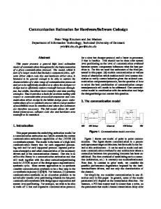
3 Overview 3.1 Cray XD1 Overview A Cray XD1 system is composed of multiple chassis, each containing up to six compute blades. Each compute blade contains two single- or dual-core 64-bit AMD Opteron processors, a RapidArray processor which provides two 2-GBps RapidArray links to the switch fabric, and an application acceleration module [4, 7] (Fig. 1). The application acceleration module is an FPGA-based reconfigurable computing module that provides an FPGA complemented with a RapidArray Transport (RT) core providing a programmable clock source, and four banks of Quad Data Rate (QDR) II SRAM. Cray presently offers a choice between several members Xilinx Virtex-II Pro and Virtex-4 families of FPGAs on the XD1. Cray provides an API that includes functions to program the FPGA, write values and addresses to registers on the FPGA, taking care of virtual to physical address translation in the latter case.
2 Related Work The Floyd-Warshall algorithm was first proposed by Robert Floyd in [6]. Floyd based his algorithm on a theorem of Warshall [16] that describes how to compute the transitive closure of boolean matrices. Venkataraman et al. proposed a blocked implementation of the algorithm to optimize it for the cache hierarchy of modern processors[15]. Apart from the Floyd-Warshall algorithm, All-Pairs Shortest-Paths (APSP) algorithms with lower time complexity exist. Karger [9] solved undirected APSP with nonnegative edge-weights in O(Mn + n2 log n) time, where n is the number of vertices in the graph and M is the the number of edges participating in shortest-paths. Zwick [10] obtained an O(n2.575) APSP algorithm where the dependence of the running time is polynomial in the maximum magnitude of the edge weights. It is thus only effective when the edge weights are integers of small absolute value. Researchers have recently demonstrated the competitiveness of FPGAs with modern processors for doubleprecision floating-point arithmetic and dense linear algebra operations, showing them to be an attractive option for high-performance scientific computing [14, 13, 21, 18]. All of these works involve proposing parallel designs followed by an analysis of design trade-offs and performance projection. In [11], Tripp et al. consider some of the integration
RAM
AMD Opteron
HyperTransport I/O Controller
RapidArray communication processor To Switch Fabric
1.6 GB/s 1.6 GB/s
FPGA Module
Figure 1. Cray XD1 System 3.2 The All-Pairs Shortest-Paths Problem Given a weighted, directed graph G = (V, E) with a weight function {w : E → R}, that maps edges to realvalued weights, we wish to find, for every pair of vertices u, v ∈ V , a shortest (least-weight) path from u to v, where the weight of a path is the sum of the weights of its constituent edges. Output is typically desired in tabular form: the entry in u’s row and v’s column should be the weight of a shortest path from u to v. 3.3 Floyd-Warshall algorithm Overview The Floyd-Warshall algorithm uses a dynamic programming approach to solve the all-pairs shortest-paths problem 2
1: 2: 3: 4: 5: 6: 7: 8:
for k ← 1, N do for i ← 1, N do for j ← 1, N do d[i, j] ← min (d[i, j], d[i, k] + d[k, j]) end for end for end for Output: d
simple and modular design that maximizes parallelism. The design scales well when – (1) larger FPGAs are employed, or (2) greater I/O bandwidth to the system is available. Global PE Control
control p1
I/O Engine
p2
Figure 2. The Floyd Warshall Algorithm
l
PE0
l
PE1
PE(r)
l
PE(B−1)
Results
on a directed graph [3, 6, 16]. It runs in Θ(|V |3 ) time. Let if i = j, 0 wi j = weight of edge (i, j) if i 6= j and (i, j) ∈ E, ∞ if i 6= j and (i, j) ∈ / E.
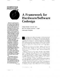
Figure 3. Parallel FW Kernel Architecture Fig. 3 shows the architecture. A linear array of B PEs is used to perform FW on a BxB matrix. Each PE has l operators where each operator comprises a comparator and an adder. The rth PE stores the rth pre-computed pivot row and column, and the work it performs corresponds to the computation in the iteration k = r of the outer loop of FW. The first and the last PE read and write data respectively, from/to the I/O engine. The design is a streaming one, with read, compute and write pipelined. l represents the doAll parallelism in each PE and is governed by the I/O bandwidth and the size of the distance matrix elements. B is constrained by the amount of FPGA resources. The product of B and l is the degree of parallelism of our design, and this was maximized under resources constraints using a model. The FW kernel described above can handle only matrices of size BxB. For the general case of NxN matrices, we extended the kernel for a blocked algorithm proposed by Venkataraman et al. in [15] with minor changes.
(k)
Let di j be the weight of a shortest path from vertex i to vertex j for which all intermediate vertices are in the set {1, 2, . . ., k}. For k = 0, we have di0j = wi j . A recursive definition from the above formulation is given by: ( wi j � � if k = 0 k di j = k−1 k−1 k−1 if k ≥ 1 min di j , dik + dk j
The matrix {diNj }, 1 ≤ i, j ≤ N gives the final result. The above recursive definition can be written as a bottom-up procedure as shown in Fig. 2. As can be seen in Fig. 2, the code is tight with no elaborate data structures, and so the constant hidden in the Θ-notation is small. Unlike many graph algorithms, the absence of the need to implement any complex abstract data types makes FW a good candidate for acceleration with an FPGA. 3.4 Overview of Parallel Blocked FW kernel
t t+B−1
In this section, we give a brief description of the parallel FPGA-based FW kernel that we designed in [1]. In the FW computation, we have exactly N 2 data elements, but Θ(N 3 ) computations to perform. Hence, there is high temporal locality that a custom design can exploit. The FW nested code has significant data dependences. Extracting parallelism in the presence of these dependences without data access conflicts making maximum use of available FPGA resources is a major challenge. Let d be the distance matrix of a directed graph of B nodes. In the nested loop code shown in Fig. 2, at any iteration k = r of the outer loop, the vectors, d[r, ∗] and d[∗, r], update the whole matrix d. We call this row and column, the pivot row and the pivot column, respectively. In order to extract parallelism from the k loop, the computation was reorganized into a sequence of two passes: first compute the set of pivot rows and columns, and then use the stored pivot rows/columns to compute the updates to matrix elements in a streamed fashion. This approach enabled the creation of a
Iteration k=t to k=t+B−1
self−dependent
+, min partial row/column dependent B
doubly−dependent
B
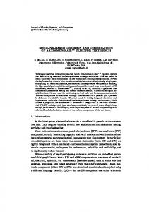
Figure 4. Tiled implementation proposed in [15] In this extended FW kernel, four kinds of tiles exist depending on the source of the pivot rows and columns that update a particular tile (see Fig. 4): 1. Self-dependent: pivot row and column are precomputed from the same tile (the original case) 3
made to the FPGA. Once the computation starts, all of the tiles placed in the source buffer are processed successively. As the computation for successive tiles is overlapped in the FPGA design (Sec. 3.4), the overhead associated with making the compute request is hidden when a large enough number of tiles are processed successively.
2. Partial row-dependent: pivot rows come from a different tile while pivot columns are computed from the same tile 3. Partial column-dependent: pivot columns come from a different tile while pivot rows are computed from the same tile 4. Doubly-dependent: both the pivot rows and columns come from distinct tiles.
Communication buffer on system To FPGA (pull)
The optimal values for B and l for the XD1 FPGA (Xilinx XC2VP50) were determined to be 32 and 4 respectively, for a precision of 16 bits. Table 1 shows the speedup of the FPGA kernel for processing a single tile. Tile Size 8x8 16x16 32x32
FPGA-FW measured 0.42 µs 1.29 µs 4.84 µs
CPU-FW (Opteron) 1.60 µs 14.1 µs 106.5 µs
Measured speedup 3.8x 11x 22x
Matrix Copy Tiles 3X
Resource utilization 34% 52% 90%
Source buffer
Destination X
From FPGA (push)
buffer
Figure 5. Communication buffer model
Table 1. FPGA-FW: Resource utilization and speedup on the Xilinx XC2VP50. Allowing the FPGA to do the read and write from the communication buffer on the system’s memory frees the CPU for other tasks. In particular, it provides us the opportunity to use the CPU to copy tiles between the matrix and the communication buffer while the FPGA is computing. We discuss this in Sec. 5.2. The parallel FPGA kernel described in Sec. 3.4 was used iteratively taking care of dependences. All tiles of a particular kind (self-dependent, partial row/column dependent and doubly-dependent) are processed successively. Hence, in each of the N/B rounds of the blocked algorithm, the self-dependent tile is processed first followed by the sets of partially row and column-dependent tiles. This is followed by the processing of doubly-dependent tiles. Fig. 4 shows the different kinds of tiles in a particular round. In order to process a tile, the tile along with the pivot row and column elements is copied to the source buffer on the system interleaved in the fashion required by the kernel (Sec. 3.4). The compute request is then made to the FPGA. Hence, for a set of k BxB tiles that need to be processed successively, 3B2 k matrix elements are copied to the source buffer by the CPU. The FPGA reads from the source buffer and writes back the result tiles comprising B2 k elements to the destination buffer, and sets the completion flag. The result tiles are then copied back to the matrix by the CPU. The number of copy operations for an NxN matrix are therefore 4N 3 /B, where each operation involves a distance matrix element. It is the time consumed in these copies between the matrix and the source/destination buffers that we try to minimize/hide in the next section.
4 Design Choices and Implementation In this section, we discuss some of the design and implementation issues in integrating the parallel FPGA kernel with software on the system. 4.1 Extending for any graph size With the approach described in the previous section, we can handle a graph with a multiple of kernel tile size number of nodes. Any arbitrary size can be trivially solved by padding the distance matrix with ∞ (the largest value within the supported precision) to the next higher multiple of tile size. This is equivalent to adding additional disconnected nodes to the graph. 4.2 Data Movement and Communication A specially allocated communication buffer that is pinned to the system’s memory is used for transfer of data to/from the FPGA. The I/O engine (Fig. 3) on the FPGA transfers data of specified length to/from contiguous regions in the communication buffer. We split the buffer into two parts as shown in Fig. 5. The source and destination buffer addresses, amount of data to be transferred to/from these buffers, and the type of tile that is to be processed is communicated using a special set of registers. A write to the register meant for the destination buffer address triggers the computation on the FPGA. Completion is indicated by setting a register bit on the FPGA which the CPU polls. All of this overhead is incurred for each compute request 4
B
5 Optimizing data movement In this section, we discuss optimizations on the systemside to extract maximum performance from the FPGA kernel. The optimizations are partly model-driven and partly from analysis of measured performance of the unoptimized version which we refer to as FPGA-FW. In FPGA-FW, the three phases of copy, compute and write-back are done sequentially with the distance matrix in the original rowmajor form. The entire blocked FW for an NxN matrix comprises (N/B)3 tiled computations. Each of the BxB tiles in the matrix gets processed N/B times – once in each round. Hence, temporal locality can be exploited for copying across rounds. The copy time is proportional to the square of the tile size (B), while the number of compute operations is Θ(B3 ). However, due to the FPGA kernel performing these operations in parallel, the compute time may be reduced to a level where it is comparable to the copy time. This scenario makes several approaches that would reduce or hide the data movement costs beneficial to pursue.
After the layout transformation, the number of cache misses per BxB tile for row-wise as well as column-wise copying is exactly B2 /L, where L is the cache line size. This is true for large matrices that are at least twice as large as the cache size. The cost of transforming the layout of the matrix is a small fraction of the FW latency and does not affect performance. Padding the distance matrix is another alternative, but is not as effective as layout transformation (Sec. 6).
5.1 Layout Transformation
5.2 Compute/Copy overlap
9
FPGA-FW-32 Latency (s)
8
B
Figure 7. Transforming the layout of the distance matrix
Even after performing the layout transformation, the compute time may be comparable to the copy time for matrices that do not completely fit in the cache. As we make the FPGA responsible for transferring data between itself and the communication buffer, the host is free while the FPGA is computing. We overlap the FPGA computation for a set of k tiles with the write-back time and the copy time for the previous and next sets respectively. Two buffers are used in an alternating fashion (each for a maximum of k tiles). We perform the compute/copy overlap only for doubly-dependent tiles as the processing of these tiles dominates the compute latency for the 32x32 FPGA kernel (Table 2).
FPGA-FW (2048) Copy Time FPGA-FW (2048) Compute Time FPGA-FW (2016) Copy FPGA-FW (2016) Compute FPGA-FW (2080) Copy FPGA-FW (2080) Compute
7 6 5 4 3 2 1 0
2048 nodes
2016 nodes
Graph Size 1024 8196
2080 nodes
Figure 6. Conflict misses in FPGA-FW
Self-Dep. 0.1% 0.002%
Partly-Dep. 6.05% 0.7%
Doubly-Dep. 93.85% 99.22%
Table 2. Percentage of tiles of each kind w.r.t 32x32 FPGA kernel
In FPGA-FW, significant conflict misses occur as successive rows of a tile may get mapped to the same cache line due to size of the matrices being large and a power of two. Fig. 6 confirms this. This leads to loss of temporal locality across multiple rounds of the blocked algorithm. For column-wise copying, apart from temporal locality, spatial locality may be lost too. In addition, if the size of the cache line is greater than the size of a single row of the tile as is the case for 8x8 and 16x16 kernels, memory bandwidth is not effectively utilized. We therefore transform the layout of the input matrix so that BxB tiles of the matrix are contiguous in memory in row-major order (Fig. 7).
Optimal overlap chunk. Choosing a small chunk size (k) for compute/copy overlap would not hide overhead that is involved in requesting the FPGA to process a set of tiles. Using a large chunk size would increase the trailing nonoverlapping copy and write-back time (the first copy and the last write-back cannot be hidden). The optimal value for the compute/copy overlap chunk, k, is higher for larger matrices. We determine this in the next section. 5
Size 256 512 1024 2048 4096 8192
Compute 3.61ms 27.86ms 0.22s 1.74s 14.02s 112.06s
FPGA-FW-32 Copy 1.41ms 23.48ms 0.21s 3.01s 28.75s 282.20s
Total 5.02ms 53.36ms 0.43s 4.75s 42.77s 394.27s
FPGA-FW-LT-32 Compute Copy Total 3.66ms 1.40ms 5.07ms 27.87ms 22.58ms 50.46ms 0.22s 0.19s 0.41s 1.75s 1.80s 3.56s 14.02s 14.40s 28.43s 112.09s 115.80s 227.89s
FPGA-FW-LTOV-32 Compute Copy (non-ov) Total 3.66ms 0.43ms 4.60ms 28.68ms 1.29ms 31.05ms 0.23s 0.01s 0.24s 1.78s 0.03s 1.82s 14.39s 0.14s 14.55s 115.25s 0.68s 115.98s
Table 3. Latency breakdown for 32x32 FPGA kernel with various optimizations
6 Measurements and Analysis
6.1 Effect of Layout Transformation
The measurements for the general-purpose processor case were taken on a 2.2 GHz 64-bit AMD Opteron (as found on the XD1) with a 64 KB L1 data cache and a 1 MB L2 cache with a cache-block size of 64 bytes. GCC 3.3 with “-O3” turned on was used for compilation. The FPGA on the XD1 is a Xilinx Virtex-II Pro XC2VP50. The FPGA design was clocked at 170 MHz. The version of Cray User FPGA API used was 1.3. All measurements were for 16-bit edge weights. We use the following abbreviations to identify CPU and FPGA-based FW implementations with different optimizations throughout this section.
By operating on the bricked layout of the distance matrix, we find that the copy time for large graphs is cut down by more than two times. As shown in Table 3, the copy time for FPGA-FW-LT increases consistently by eight times as the size of the problem doubles, as opposed to the way it does for FPGA-FW. This is along expected lines (Sec. 4.2). 6.2 Effect of compute/copy overlap 450 400
CPU-FW: Simple Floyd-Warshall (FW) implementation on the Opteron (three-way nested loop shown in Fig. 2).
350
FPGA-FW-32 Copy Time FPGA-FW-32 Compute Time FPGA-FW-LT-32 Copy Time FPGA-FW-LT-32 Compute Time FPGA-FW-LTOV-32 Non-overlapped Copy Time FPGA-FW-LTOV-32 Compute/Copy Overlapped
Latency (s)
300
CPU-FW-OPT: Optimized blocked implementation of FW on the Opteron (block size empirically optimized for best performance) [15]. We copy tiles to a contiguous buffer to eliminate conflict misses.
250 200 150 100
FPGA-FW: FPGA-based implementation for FW for an NxN matrix on the XD1 FPGA without any optimizations.
50 0
FPGA-FW-LT: FPGA-FW with layout transformation as explained in Sec. 5.1.
4096
Matrix Size
8192
Figure 8. Copy/compute time breakdown with different optimizations
FPGA-FW-LTOV: FPGA-FW-LT with compute and copy overlapped as explained in Sec. 5.2.
Even after the layout transformation, for graphs with 512 nodes or more, the copy time is comparable to the compute time. The compute/copy overlap thus leads to a speedup by a factor of two hiding the copy time completely (Fig. 8). As far as the size of overlap chunk is concerned (discussed in Sec. 5.2), empirically we find that a value of 32 works well for most problem sizes (Fig. 9). Thus, the total communication buffer requirements (including the alternating buffer) are: 2 ∗ 4 ∗ k ∗ B2 ∗ 2 bytes = 512 KB. For CPU-FW-OPT, the copy time is a very small fraction of the total latency (about 1%) for all problem sizes (Table 4). The compute and copy times for CPU-FW-OPT increase along expected lines (proportional to the cube of
A suffix of 8, 16 or 32 is used to distinguish implementations using kernels that process tiles of that size. In all figures and tables, copy time refers to the sum total of both, the copy time and the write-back time. All speedup factors mentioned in this section are over the optimized CPU implementation (CPU-FW-OPT). For graphs with up to 256 nodes, the distance matrix and the communication buffer completely fit in the L2 cache (2562x2x5 bytes < 1 MB). Hence, FPGA-FW, FPGA-FWLT and FPGA-FW-LTOV perform equally well as seen in Table 3. However, there is a sudden increase in copy time from 256 nodes to 512 nodes, and performance drops from there on for FPGA-FW and FPGA-FW-LT (Fig. 10). 6
Size Compute 69.6ms 480.5ms 3.63s 28.04s 220.02s 1739.71s 13810s
256 512 1024 2048 4096 8192 16384
CPU-FW-OPT Copy Total 0.6ms 70.2ms 5.5ms 485.9ms 0.05s 3.67s 0.33s 28.37s 2.86s 222.89s 21.73s 1761.44s 171s 3 hrs 53 min
FPGA-FW-LTOV-32 Compute Copy Total 3.7ms 0.4ms 4.6ms 28.7ms 1.3ms 31.0ms 0.23s 0.01s 0.24s 1.78s 0.03s 1.82s 14.39s 0.14s 14.55s 115.25s 0.68s 115.98s 915s 2.94s 15 min
Speedup 15.2x 15.7x 15.7x 15.6x 15.3x 15.2x 15.2x
Table 4. Measured performance: comparison with CPU-FW-OPT 20
17x FPGA-FW-32 FPGA-FW-LT-32 FPGA-FW-LTOV-32
16x
14x
18
13x 12x 11x 16
Speedup
FPGA-FW-LTOV-32 latency (s)
15x
14
10x 9x 8x 7x 6x 5x 4x
12
3x 2x 1x
10 2
4
8
16
32
64
128
256
512
32
64
Overlap Chunk
512
1024
2048
4096
8192
Figure 10. Measured Speedup over CPU-FWOPT plication. For every BxB tile that is processed, 3B2 16-bit matrix elements get streamed to the FPGA, and B2 matrix elements are written back. Read, compute and write are fully pipelined. Hence, the unidirectional read bandwidth that the FPGA kernel obtains is calculated as:
the problem size). As shown in Fig. 10 and Table. 4, after all optimizations, a speedup of 15x is obtained for graphs with 256 nodes or more. For graphs with less than 256 nodes, the speedup is on the lower side due to the fact that there are not large enough number of tiles to be successively processed in each round to cover the overhead of making the compute request to the FPGA. Fig. 11 shows the final speedup for all problem sizes obtained by employing the optimized 8x8, 16x16 and the 32x32 FPGA kernels. The measured speedup doubles when the tile size that is processed in parallel doubles as we have double the number of parallel operators.
Read b/w =
6N 3 B/s B ∗ (Compute latency (N nodes))
(2)
The peak GigaOps for the Opteron is 4.4. However, the sustained GigaOps for CPU-FW-OPT as shown in Fig. 12 is far lower. This is probably due to the compare branch in the nested code. As the branch depends on input data, it can never be predicted accurately. The 32x32 FPGA kernel, having 128 operators, has a theoretical peak computational rate of 51.2 GigaOps. However, as two-thirds of the time is spent in pre-computing/shifting pivot row and column elements, the peak performance is reduced to 17.1 GigaOps which would be possible at the peak bandwidth of 1.6 GB/s theoretically. However, the bandwidth sustained from the system to the FPGA with our I/O kernel is much lower at about 860 MB/s (Fig. 13). FPGA-FW-LTOV-32 thus sustains only 9.23 GigaOps out of 17.1.
6.3 Sustained GigaOps and Memory Bandwidth Fig. 12 compares GigaOps performance of the optimized CPU and FPGA implementations. For GigaOps, we consider add and compare as operations, and is given by: 2N 3 Measured FW latency ∗ 109
256
Matrix Size
Figure 9. Optimal Compute/Copy Overlap Chunk (for 2048 nodes)
FW GigaOps =
128
(1)
Fig. 13 shows the bandwidth we measure for the FW ap7
17x
1000 FPGA-FW-LTOV-8 FPGA-FW-LTOV-16 FPGA-FW-LTOV-32
16x 15x
FPGA-FW-32 FPGA-FW-LT-32 FPGA-FW-LTOV-32
14x
800
13x
Bandwidth (MB/s)
12x
Speedup
11x 10x 9x 8x 7x 6x 5x
600
400
4x 200
3x 2x 1x
0 32
64
128
256
512
1024
2048
4096
8192
32
Matrix Size
256
512
1024
2048
4096
8192
Figure 13. Measured read bandwidth from the XD1 to the FPGA kernel
toh : tc : tcp : twb : k :
CPU-FW-OPT FPGA-FW-32 FPGA-FW-LT-32 FPGA-FW-LTOV-32 FPGA-FW-LTOV-16 FPGA-FW-LTOV-8
9
128
Matrix Size
Figure 11. Performance Comparison: 8x8, 16x16 and 32x32 kernels
10
64
8
Overhead for processing a set of tiles successively Compute time for a BxB tile Copy time to source buffer to process a single BxB tile Write-back time for a BxB result tile overlap chunk size (number of tiles)
Billion Ops
7
As the overhead for making a compute request to the FPGA is incurred four times in each of the N/B rounds (once for each type of tile), the latency for processing an NxN matrix without overlap is given by: � �3 � � N 4N toh + (tcp + tc + twb ) (3) Lno−ov = B B
6 5 4 3 2 1 0 32
64
128
256
512
1024
2048
4096
8192
From the compute latencies of FPGA-FW-LT in Table 3, we determine: tc = 6.68 µs, tcp + twb = 7.1 µs, and toh = 9.9 µs, for B = 32. With compute copy overlap for doubly-dependent tiles, we have: � � �3 � N N 3N ∗ max(tc ,twb + tcp ) toh + + Lov = B B∗k B + k (tcp + twb ) (4)
Matrix Size
Figure 12. CPU-FW-OPT vs. FPGA-based FW: Billion OPS performance
It is important to note that overlapping copying of tiles with the FPGA computation does not lead to a significant drop in memory bandwidth available to the host. As the FPGA computation contends with the copy operations for the memory bus (Fig. 1), the compute time for FPGA-FWLTOV-32 is marginally higher than that of FPGA-FW-LT (Table. 3).
For large matrices, the toh factor is negligible in the total latency. Hence, the compute latency for large matrices is very accurately modeled by tc ∗ (N/B)3 as shown in Fig. 14, for B = 32. The total latency for FPGA-FW-LTOV for large matrices is captured well by: � �3 N L= ∗ max(tc , tcp + twb ) (5) B
6.4 Performance model
Note that tc ∝ (B2 /l) (Sec. 3.4) and tcp , twb ∝ B2 . Using the above equation, we compare the latencies obtained from the
We build a performance model and compare the predicted results with the measured ones. Let 8
FPGA-FW-LT-32 Compute Time (s)
1024
to the FPGA would not help our application beyond a certain point where the compute time reaches the level of data movement costs on the system. In fact, with our design on the XC2VP50, and with the bandwidth we obtain, we reach this point for larger graphs. We use the model built in the previous section to illustrate this effect in Fig. 16: greater I/O bandwidth beyond a certain point would be desirable only if more FPGA resources are available.
Measured Model
256
64
16
4
1
Speedup
0.25
30
2048
4096
8192
16384
25
Matrix Size
32
20 15
16
Figure 14. Measured compute time vs. Model for FPGA-FW-LT-32
10 8
5 0
4 64
2
model for B = 8,16 and 32 in Fig. 15. Note that l = 4 for all the three kernels.
32
12 4
PE Parallelism - l
16
Block size - B
8 16 8
Measured Model
FPGA-FW-LTOV Latency (s)
256
Figure 16. Impact of FPGA–System Bandwidth and FPGA Resources on FPGA-FWLTOV for 8192 nodes: Eqn. 5
64
16
6.6 Performance improvement on a real dataset
4
Dynamic Transitive Closure Analysis (DTCA) is a recent algorithmic development for analysis of interaction and similarity networks of biological systems [17]. Although the method was developed to evaluate undirected graphs representing large gene-drug interaction networks in the study of cancer, it can be used to evaluate any large interaction network. The method incorporates repeated All-Pairs Shortest-Paths evaluations, which are a computational bottleneck for analysis of very large networks. A scalable implementation of the DTCA algorithm was implemented in a software program called Galaxy as part of the Ohio Biosciences Library [5, 2]. Reading in microarray expression data for several genes and drugs, the program utilizes the Floyd-Warshall (FW) algorithm to evaluate for closure on multiple subgraphs of the original interaction network. The vertices of the graph represent either genes or drugs under investigation in the study of new therapies for treating cancer. The weight of an edge in the graph is calculated using the co-correlation value computed between each pair of vertices using the microarray expression data provided for each gene and drug involved in the study. The distance used for each edge is 1 − c2 , where c is the computed co-correlation value.
1
0.25 8x8
16x16
32x32
FPGA Kernel Size
Figure 15. FPGA-FW-LTOV latency for 8192 nodes with various kernels: Measured vs. Model (Eqn. 5)
6.5 Impact of I/O bandwidth and FPGA resources The number of elements copied during FPGA-based FW on an NxN matrix is 4N 3 /B. A larger tile size would lead to the complete matrix getting processed in terms of larger blocks, and so fewer copies. An increase in FPGA area would increase the tile size that would be processed in parallel (B). Thus, a higher value of B would reduce both, the compute time (due to pipelined parallelism) and copy time. An increase in I/O bandwidth improves only the compute time as a result of higher doAll parallelism in each PE. Therefore, an increase in I/O bandwidth from the system 9
For the application described above, all edge-weights are fractions between 0 and 1, with an accuracy up to three places of decimal desired. Hence, all of these weights can be scaled to integers between 0 and 1000 making a precision of 11 bits sufficient. We particularly consider a large instance of this problem – a graph with 22,740 nodes with FW called 100 times. The runtime for this particular instance is 21 days on the Cray X1 (using eight vector pipes on an MSP), and 43 days on the Opteron. With FPGA-FWLTOV-32, the run-time is reduced to 2 34 days.
[7] [8] [9]
[10]
7 Conclusions [11]
In this paper, we developed optimizations that enable high application-level speedup for blocked algorithms employing parallel FPGA kernels. Using a parallel FPGAbased Floyd-Warshall design developed in [1], the proposed optimizations minimize system-size data movement costs to effectively solve large instances of the All-Pairs Shortest-Paths (APSP) problem on a reconfigurable supercomputer. On the Cray XD1, these optimizations improve the application-level speedup of FPGA-based APSP over an optimized implementation on a modern general-purpose processor from 4x to 15x for large graphs. A model was developed to accurately characterize the latency of the optimized FPGA implementation, and provide an insight into the impact of memory bandwidth and FPGA resources on the achieved speedup. The techniques developed apply to other blocked FPGA-accelerated routines for which the speedup with the FPGA kernel is high enough to make orchestrating movement of data on the system critical. With the current trends in FPGA and CPU performance, these approaches would become increasingly important for most FPGA-based routines on reconfigurable supercomputers.
[12]
[13]
[14]
[15]
[16]
References
[17]
[1] Uday Bondhugula, Ananth Devulapalli, Joseph Fernando, Pete Wyckoff, and P. Sadayappan. Parallel FPGA-based All-Pairs Shortest-Paths in a Directed Graph. In Proceedings of the 20th IEEE International Parallel and Distributed Processing Symposium (IPDPS’06), April 2006. To be presented. URL http: //www.cse.ohio-state.edu/∼ bondhugu/ipdps06.pdf. [2] The Ohio Supercomputer Center. Ohio Biosciences Library. URL http://www.osc.edu/research/ bioinformatics/projects/obl/index.shtml. [3] Thomas H. Cormen, Charles E. Leiserson, and Ronald L. Rivest. Introduction to Algorithms. The MIT Press, second edition, 2001. [4] Cray Inc. Cray XD1, 2004. http://www.cray.com/products/xd1/. [5] D. P. Dougherty, E. A. Stahlberg, and W. Sadee. Network Analysis Using Transitive Closure: New Methods for Exploring Networks. Journal of Statistical Computation and Simulation, 2005. [6] Robert W Floyd. Algorithm 97: Shortest Path. In
[18]
[19]
[20]
[21]
10
Communications of the ACM, volume 5, page 345. ACM Press, 1962. Cray Inc. Cray XD1 Whitepaper, 2005. http://www.cray.com/products/xd1/. SRC Computers Inc. SRC MAPstation. http://www.srccomp.com/MAPstations.htm. David R. Karger, Daphne Koller, and Steven J. Phillips. Finding the hidden path: Time bounds for all-pairs shortest paths. In IEEE Symposium on Foundations of Computer Science, pages 560–568, 1991. Avi Shoshan and Uri Zwick. All pairs shortest paths in undirected graphs with integer weights. In IEEE Symposium on Foundations of Computer Science, pages 605–615, 1999. Justin L Tripp, Anders A Hansson, Maya Gokhale, and Henning S Morveit. Partitioning Hardware and Software for Reconfigurable Supercomputing Applications: A Case Study. In Proceedings of ACM/IEEE Supercomputing, November 2005. Justin L. Tripp, Henning S. Mortveit, Anders A. Hansson, and Maya Gokhale. Metropolitan road traffic simulation on fpgas. In Proceedings of the IEEE Symposium on Field-Programmable Custom Computing Machines (FCCM), 2005. Keith Underwood. FPGAs vs. CPUs: Trends in peak floating-point performance. In Proceedings of ACM/SIGDA Symposium on FPGAs, 2004. Keith D. Underwood and K. Scott Hemmert. Closing the Gap: CPU and FPGA Trends in Sustainable Floating-Point BLAS Performance. In Proceedings of the IEEE Symposium on Field-Programmable Custom Computing Machines (FCCM), 2004. G. Venkataraman, S. Sahni, and S. Mukhopadhyaya. A Blocked All-Pairs Shortest-Paths Algorithm. J. Exp. Algorithmics, 8:2.2, 2003. Stephen Warshall. A Theorem on Boolean Matrices. In Journal of the ACM, volume 9, pages 11–12. ACM Press, 1962. X. Zhou, M.C.J. Kao, and W.H. Wong. Transitive Functional Annotation by Shortest-Path Analysis of Gene Expression Data. In P. Natl. Acad. Sci., USA, 2002. Ling Zhuo and Viktor K. Prasanna. Design Trade-offs for BLAS Operations on Reconfigurable Hardware. In ICPP, pages 78–86, 2005. Ling Zhuo and Viktor K. Prasanna. Sparse Matrix-Vector multiplication on FPGAs. In Proceedings of ACM/SIGDA 13th International Symposium on Field-programmable Gate Arrays, pages 63–74, 2005. Ling Zhuo and Viktor K. Prasanna. High Performance Linear Algebra on a Reconfigurable Supercomputer. In Proceedings of ACM/IEEE Supercomputing, November 2005. Ling Zhuo and Viktor K. Prasanna. Scalable and Modular Algorithms for Floating-Point Matrix Multiplication on FPGAs. In Proceedings of the International Parallel and Distributed Processing Symposium (IPDPS), 2004.