data path architecture with optimum scheduling of opera- ... gorithm and explains the hardware and software environment used. In section 3 the design method ...
HARDWARE-SOFTWARE CODESIGN OF A TIGHTLY-COUPLED COPROCESSOR FOR VIDEO CONTENT ANALYSIS Juergen Wassner, Klaus Zahn, Ulrich Dersch Lucerne University of Applied Sciences and Arts, Switzerland {juergen.wassner,klaus.zahn,ulrich.dersch}@hslu.ch ABSTRACT
it is not unusual that the overhead inferred by this communication completely offsets the benefit coprocessors are able to provide. It therefore seems natural to focus on methods that minimize the communication overhead between FPGA, CPU, and memory. One way to do so, are tightly-coupled coprocessors (TCC). Such coprocessors can be realized efficiently if the CPU is embedded into the FPGA, as is the case for instance with Xilinx Virtex-5 devices.
Hardware acceleration is a popular method to boost performance in video processing applications. This paper shows how to accelerate such applications on a general-purpose CPU by means of a coprocessor that is tightly-coupled to the instruction pipeline. A method for efficient data transfer between CPU and coprocessor is developed, and the resulting data path architecture with optimum scheduling of operations is demonstrated. Based on this method, a coprocessor has been implemented in a Virtex-5 FPGA with embedded PowerPC to accelerate candidate operations of a video content analysis algorithm. Experimental results indicate that with a relatively small degree of parallelism, corresponding to modest hardware cost, the overall frame rate can be increased between 18 and 105 % depending on processing and application parameters.
A similar TCC setup was recently used in [3] to propose dynamic instruction set extension, but applied to floating point operations. Previous work on FPGA-based VCA acceleration includes [4], where an efficient geometrical moment engine was developed and evaluated in a hypothetical multiprocessor environment. The same authors made architectural explorations for such environment by means of simulation [5]. A quantitive analysis of FPGA speedup factors for typical image processing operations was presented in [6]. The anticipated speedup factors of 20 to 100 are based on the analysis of three isolated filtering operations, which perfectly lend themselves to FPGA implementation. Opposed to this, experimental results in the paper at hand represent the potential of coprocessors in VCA for real-world applications. Furthermore, while the analysis in [6] is based on abstract measures like instruction efficiency and rated number of clock cycles, a more practical approach is taken here by using actual frame rates as the ultimate performance indicator.
Index Terms— Video signal processing, Coprocessor, Hardware acceleration, Field programmable gate arrays 1. INTRODUCTION During the past five or so years hardware acceleration for image and video processing has entered the mainstream. While in high performance computing environments GPUs are commonly employed, FPGA-based acceleration has gained popularity for embedded systems [1]. Hardware system vendors offer a variety of platforms for FPGA-based coprocessors that ought to improve performance in highly parallel regions of the software code. The inner loops of arithmetical computations performed in two-dimensional signal processing represent such regions. Nevertheless, still relatively few quantitive data is available on overall speedup factors FPGA-based accelerators can achieve in real-world video content analysis (VCA) applications. Presumably the main obstacle in utilizing the enormous processing power of FPGAs is the need for communication with the system memory, the CPU, or both. Issues like limited memory bandwidth, arbitration of several clients that require access to one and the same resource, and data synchronization make it notoriously difficult to amortize the cost of communication between FPGA, memory and CPU. As noted in [2],
978-1-4244-8933-6/10/$26.00 ©2010 IEEE
The main contributions of this paper are twofold. First, a method for efficient data transfer between a CPU and a tightly-coupled coprocessor is systematically developed. This method can be applied to any two-dimensional signal processing task and serve as the basis for automated design of such coprocessors. Second, quantitive results obtained from a FPGA implementation of a so designed coprocessor are presented. These results indicate speed-up factors as a function of processing parameters in a real-world VCA application. The rest of the paper is organized as follows: Section 2 identifies operations to be accelerated in the target VCA algorithm and explains the hardware and software environment used. In section 3 the design method for the coprocessor is developed. Experimental results are presented in section 4 and the paper is concluded in section 5.
87
SiPS 2010
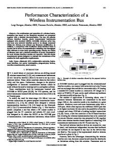
Fig. 1. VCA processing flow, with highlighted operations to be accelerated. 2.2. System Architecture In general, coprocessors can be linked to a CPU in three different ways as shown in Fig. 3. While a quantitative comparison between the three system architectures is beyond the scope of this paper, we briefly discuss their general implications here. In Fig. 3(a) the coprocessor is a slave device on the system bus and its local memory must be served by the CPU via a high-latency path. If the coprocessor can access the main memory directly, see Fig. 3(b), the CPU is freed from transferring data to the coprocessor. However, the required arbitration increases bus latency, and the memory bandwidth available for the CPU is reduced. With a tightly-coupled coprocessor (TCC) as in Fig. 3(c) the memory bandwidth for the CPU remains unchanged, at the cost of the CPU being in charge of all data transfers to and from the coprocessor. However, such transfers are less costly than in Fig. 3(a), because data between CPU and coprocessor is now exchanged via a specialized and highly efficient interface, which links the CPU instruction pipeline and the TCC. In case of the PowerPC440x5 integrated into Xilinx Virtex5-FXT FPGAs, the specialized interface is formed by an Auxiliary Processing Unit (APU). Since the PowerPC CPU is embedded as a hard macro within the FPGA itself, high transfer rates become feasible. For the implementation at hand an APU-interface rate of 200 MHz was achieved, which is half the CPU clock frequency of the target system.
Fig. 2. Visualization of major VCA processing steps (a-c) and respective share of CPU time (d) for operations from Fig. 1.
2. HW/SW ENVIRONMENT 2.1. Target Application Fig. 1 shows the flow of operations within the VCA target application. Starting from the input image, see Fig. 2(a), segmentation is performed via background subtraction, which is based on pixel-wise gradient calculation. The subsequent binning of the results in eight equally spaced orientation bins is visualized by different colors in Fig. 2(b). The orientation fluctuation of each pixel is analyzed over time and background (constant orientation) and foreground (changing orientation) pixels are extracted. After successive application of erosion and dilation operations, the foreground pixels are clustered to form the blobs as shown in grey scale in Fig. 2(b). Segmentation is followed by a feature tracking analysis [7], see Fig. 2(c). Detected features and their history are represented by circles and lines, respectively. This analysis is limited to the foreground pixels obtained during segmentation, thereby considerably reducing the processing time required. The corresponding software implementation has been ported to the target platform described in section 2.2. By profiling the code, candidate operations for hardware acceleration have been identified. Four operations were selected, cf. Fig. 1, which all work by row-wise iteration over all frame pixels. As shown in Fig. 2(d), the four operations to be accelerated consume about two thirds of the total CPU time for a typical parameter setting (see section 4.1).
2.3. Coprocessor Architecture The architecture of the VCA coprocessor and its interface to the CPU are shown in Fig. 4. The APU continuously monitors the CPU instruction pipeline and dispatches any user-defined instruction (UDI) to the TCC. Only non-autonomous UDIs have been used, which can provide two 32-bit operands from the CPU register file to the TCC and return one 32bit result from the TCC back to the CPU register. With non-autonomous instructions, the CPU instruction pipeline is stalled while the UDI is being processed by the TCC. A sequence of UDIs that provide operand data and return results that the TCC calculates from that data, is called a TCC transaction. Upon completion of every transaction the TCC returns to its idle state. This implies that the TCC is unaware of the overall state of frame processing. The TCC solely maintains the state of the current transaction, stores operand data, and invokes its internal processing module corresponding to the type of UDI received from the APU. For byte-oriented video processing the TCC can be
88
(a)
(b)
(c)
Fig. 3. System architecture with CPU and coprocessor loosely coupled via system bus (a) or memory controller (b), and tightly coupled to the instruction pipeline (c). exactly once. However, the TCC can not access main memory and its only local storage is the input data array as shown in Fig. 4. This array is realized by flip-flops rather than BlockRAM in order to give each of the eight parallel processing units flexible single-cycle access to multiple input data bytes, and still maintain a regular, and hence scalable storage structure. Consequently, it is crucial to keep the size of the array as small as possible. On the other hand, with a minimum size array equal to the operation mask size, only one result pixel can be returned per transaction. Such byte-wise operation is inefficient on a 32-bit architecture. Hence, the number of times a pixel must be transferred has been minimized only to such an extent that allows to build the local TCC memory from flip-flops, but still make efficient use of the bandwidth available between CPU and TCC. This compromise resulted in the data transfer organization shown in Fig. 5(top) for a 3x3 mask. For this mask size, three UDIs make up one transaction. The first two UDIs convey pixel data to the first stage of the input array. The second and third UDI return result data. At the end of any transaction, first stage data becomes second stage data, and so on. The offset of the result data relative to the first stage input data is chosen such that one pixel remains unprocessed at the frame edge. Note that the number of columns in the input data array (twelve), as well as the number of result pixels computed per transaction (eight) are multiples of four. This is because four pixels make up a 32-bit UDI operand and result, respectively. Similarly, the number of rows in the input data array (four) is a multiple of two. This is because two operands can be transferred per UDI. The 3x3 data transfer principle can be formally extended to accommodate arbitrary mask sizes, see Fig. 5(bottom). Let r and c be the number of rows and columns of the filter mask at hand. Given that each UDI comprises two operands and one result, each consisting of b bytes, then all quantities that define the data transfer organization can be computed from the three parameters r, c = 1, 3, 5, . . . and b ≥ 1 as follows. The offset of result pixel R1 in y- and x-direction is given by
Fig. 4. VCA coprocessor architecture. The APU dispatches user-defined instructions (UDI) from the CPU instruction pipeline together with two 32-bit operands to the input data array of the TCC. Results computed by any of the eight-fold processing units are returned via the APU. viewed as an application-specific SIMD (single instruction, multiple data) extension for the 32-bit embedded PowerPC processor. The degree of parallelism of that extension is given by the 32-bit data interface between TCC and CPU, and is comparatively small. In the following section a method is described to utilize this given interface efficiently, such that a net speedup of the VCA algorithm can be achieved. 3. HW/SW CODESIGN 3.1. Data transfer organization
dy
As noted above, the efficiency of the TCC is determined by the efficiency of the data transfer to and from the coprocessor. Ideally, to minimize the communication overhead, each pixel in the video frame to be processed is transferred to the TCC
dx
89
r−1 2 � � c−1 = ·b b
=
(1) −
c−1 2
(2)
3x3 data transfer
3x3
5x5
5x7
Fig. 5. Top: Data transfer principal for row-wise computation of eight result pixels per transaction with a 3x3 mask. Result data from the first transaction in each row are discarded. Third stage input data is shown for reference only, but not actually used for 3x3 mask size (cf. equation (3)). Bottom: Offset dy and dx of result pixel R1, and latency-critical result pixel and associated latency-critical operands indicated for 3x3, 5x5 and 5x7 mask sizes. Note that offset dy is calculated for 7x7 instead of 5x7 mask, because results for both 5x7 and 7x5 masks are computed within the same transaction. respectively. The offsets dy and dx are then realized for each mask size as defined by equations (1) and (2) by maintaining the appropriate offset between source and destination pointers in software, see section 3.3.
Equation (1) follows directly from the number of pixels left unprocessed at the frame edges. Equation (2) additionally takes into account the operand word with b. These offset values ensure the minimum size of the input data memory for a given mask size. The number of stages s in the input data memory is � � c−1 + 1 (3) s = b
3.2. Data path design The goal in data path scheduling is to achieve minimum processing latency for the given data transfer scheme. Since each location in the input data array is updated at most once during any transaction and held stable afterwards, it is possible to schedule operands at any time after they are updated. On the other hand, timing constraints limit the number of operations that can be performed within one clock cycle. Hence, from a pure latency point of view, the broadest tree structure that complies with the timing requirements would be optimal. However, since not all input operands are available with the first UDI, the tree must be modified such that late operands can be chained into the tree at appropriate points.
From this, the total size (rows × columns) of the input data memory follows: memory size = =
(r + 1) × b · s �� � � c−1 (r + 1) × b · + 1 (4) b
Note that it is possible to reuse the same input data memory for computations with different mask sizes. In this case, the number of stages s and the total memory size is determined by the largest mask size according to equations (3) and (4),
90
// source & dest. pointer with offset int* s = src_frame; int* d = dst_frame+nCol-3; // dy=1,dx=3 iCol = nCol>>2; // 4 cols per transact. for(r = 1; r < nRow-2 ; r+=2){ // fetch operands, 4 byte each ra = s[ 0]; // n_1_A rb = s[ iCol]; // n_1_B rc = s[2*iCol]; // n_2_A rd = s[3*iCol]; // n_2_B // load operands, return dummy results UDIx(r1, ra, rb); //(Res, Op_A, Op_B) UDIx(r1, rc, rd); UDIx(r2, rc, rd); // incr. source & dest. pointer s++; d++; for(c = 1; c 12.5 fps) for CIF resolution. Also, absolute frame rates become nearly independent on the mask size used, because all major operations that depend on the mask size have been accelerated. Thus, higher quality results due to processing with larger masks become possible without a significant frame rate penalty.
[3] M. Grad and C. Plessl, “Woolcano - an architecture and tool flow for dynamic instruction set extension on Xilinx Virtex-4 FX,” in Proc. IEEE Symposium on Field Programmable Custom Computing Machines, 2009. [4] J.A. Vijverberg and P.H.N. de With, “Hardware acceleration for tracking by computing low-order geometrical moments,” in IEEE Workshop on Signal Processing Systems, 2008, pp. 43–48. [5] J.A. Vijverberg and P.H.N. de With, “Architecture exploration of an embedded multi-processor for video content analysis,” in Proc. ProRISC, 2008. [6] Z. Guo, W. Najjar, F. Vahid, and K. Vissers, “A quantitative analysis of the speedup factors of FPGAs over processors,” in FPGA’04: Proc. of ACM/SIGDA 12th Int. Symp. on FPGAs, New York, USA, 2004, pp. 162–170. [7] C. Kaas, J. Luettin, R. Mattone, and K. Zahn, “Evaluation of a self-learning event detector,” in Video Based Surveillance Systems: Computer Vision and Distributed Processing. 2001, pp. 205–214, Kluwer Acad. Publ.
92