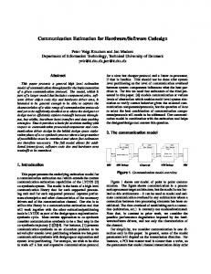
To appear in Proc. of EuroDAC/EuroVHDL, Brighton, U.K., Sept. 1995
High-Level Synthesis and Codesign Methods: An Application to a Videophone Codec Pierre Paulin, Jean Fréhel, Michel Harrand, Elisabeth Berrebi, Clifford Liem, François Naçabal, Jean-Claude Herluison SGS-Thomson Microelectronics 850, rue Jean Monnet BP 16 - 38921 Crolles cedex - France Email:
[email protected] (or
[email protected])
Abstract This paper describes a high-level multi-HDL design process applied to an industrial design of a single chip Videophone Codec. It makes use of many state-of-the-art design tools and methods:
• Behavioural VHDL control path synthesis for the controller of the Codec motion estimator.
• Behavioural DSP synthesis from Silage to generate an application-specific calculation unit that performs vector prediction for the motion estimator.
• Retargetable C compilation for an embedded application-specific microcontroller.
• Multi-level (behavioural, RTL, gate) and multi-language (VHDL, Silage, C) co-simulation. We will show that, with respect to a manual design process, the use of these tools led to the following results:
• A five-fold reduction in the source HDL description complexity.
• Equal or better timing performance. • Silicon area within 15% (4% area overhead for the
1. Introduction While there has been much talk on the necessity of a major breakthrough in design methods and advanced CAD to support the multi-million gate chips that are already a reality [Paul95a], there have been very few examples of industrial success in the application of state-of-the-art synthesis and microcode compilation tools. The focus of this paper is the description of a design experiment at SGS-Thomson which made use of advanced tools in these key areas. The emphasis here is on the methodology and the lessons learned, not the technical aspects of the tools used. The latter can be found elsewhere, e.g. [KiDJ94], [KiDJ95], [DeMa90], [Vern94], [Vald95], [Liem95], [Paul95b]. The target project is a production single-chip videotelephone codec, the STi1100 [STM93]. This chip simultaneously encodes and decodes 15 QCIF (144x176 pixels) images per second, according to the H.261 standard. A block diagram of the Codec is given in Figure 1. Bit-stream in
Unframer
DSP operator, and 14% overhead for the controller).
• Automatically compiled assembly code (from ANSI C descriptions) that is as compact as hand-coded assembler. We also identified a strong need to pay attention to design verification issues, especially when dealing with multi-level descriptions and multiple languages. Validation of the design was the single most time consuming part of the process.
Pictures in
VLC -1
Reconstruction: Q -1, DCT -1
Grabber
Bit-stream out
Coding: Motion VLC/ Estimator DCT, Q, Framer Formatting
Command Bus Data Bus
Prgm ROM
MSQ: microcontroller
Display Contr. Interface
Display Controller
MCC: Memory Controller
Host @ Interface
Data Address VRAM
Host Bus
Figure 1: Videophone Codec block diagram
A more detailed description of the chip’s functionality and design is given in [Harr95]. For the purpose of this paper, we need to distinguish two distinct design paths: 1. The original design methods used for the existing chip in a CMOS 0.7 micron process at SGS-Thomson (which is currently being ported to 0.5 micron CMOS). 2. A subsequent redesign using the new design methods and tools which are the focus of this paper. These methods where validated and quantified by comparing with the results for the production design above. The next section will describe the original design process. This will be followed by a description of the process used for the design experiment, with particular emphasis on the retargetable compiler and the co-simulation issues involved. We present results for the entire design experiment and conclude with an outlook on the emerging process which will be applied in the next generation codec.
As shown in Figure 2, all of the transformations of the algorithm and behavioural level design to the register-transfer level (RTL) were performed manually. This holds for the hardware blocks, where a synthesizable RTL description is written; as well as for the programmable components, where the instruction-set is defined manually, and the VHDL behaviour is translated to assembly code by hand. This transformation is time consuming and error-prone. Algorithm
Behavior
C code
Test Manual Vectors Translation VHDL H/W Behav.
VHDL MSQ S/W Behav. Instruction Set
Manual Design
Manual Design
RTL
VHDL RTL Description
VHDL RTL: MSQ
Manual Translation Assembly Code
2. Initial design process The design process used for the production chip is shown in Figure 2. It is characterized by a fairly elaborate front-end design process which exploits executable specifications which are technology and implementation independent. This front-end design process makes use of abstraction levels well above those supported by commercial implementation tools. As a result, there are many design refinement steps which were performed manually. The first step consists of the definition of an executable specification of the video algorithms to be supported. This specification is written in ANSI C, and is based on the videophone H.261 standard. The resulting image data obtained from program execution is stored in data files and used as test vectors for the next step. A coarse architecture partition is then performed, with an assignment of functions to specific operators. These correspond to the blocks in Figure 1. An implementation independent description of the behaviour of these operators is written in VHDL. Each behaviour is described as a VHDL process, with only high-level timing. A handshake-based communication is used to synchronize the communication of the parallel operators via a data/control communication bus. The next step consists of the partition of the overall functionality into hardwired blocks and microprogrammable ones. This partition is done manually, based on estimates of required throughput. All complex control functions are assigned to dedicated microcontrollers, the MSQ and the MCC, shown as round boxes in Figure 1. High-throughput functions like direct and inverse discrete cosine transforms (DCT) and motion estimation are assigned to hardwired components (square boxes).
Netlist
Commercial RTL Synth.
Assembler
VHDL Netlist
Binary code
Figure 2: Initial Design Process
3. New Design Process As shown in Figure 3, three new tools were used in this design experiment: 1. Amical: A control-oriented high-level synthesis tool developed at the TIMA lab of the Institut National Polytechnique de Grenoble (INPG) [KiDJ94], [KiDJ95]. 2. Cathedral-2/3: A DSP-oriented high-level synthesis tool developed at IMEC [Vern94], [DeMa90]. 3. FlexWare: An environment for the design of embedded software [Paul95b]. In the current experiment, only the retargetable compiler was used. The Insulin instructionset simulator [SuPa94] will be used in the next design. The motivations for using these tools were twofold: 1. Higher productivity through the use of higher levels of abstraction. In the original design process, two activities consumed nearly 50% of the total design time: i) the manual translation of the behavioural VHDL code to the RTL description (25% of design time), and ii) the co-simulation of the RTL VHDL with the VHDL testbench to validate its correctness (24% of design time). Both of these activities become unnecessary with the use of high-level synthesis and compilation tools. 2. Architectural style independence. While technology independence is achieved with current RTL synthesis tools, the architectural style is hard-coded into the RTL
2
code. The Amical, Cathedral-2/3, and FlexWare tools support various types of architecture styles, e.g. controldatapath pipeline stage in Amical; ALU pipeline stage in Cathedral-2/3; and instruction-set parameterization in FlexWare. DSP H/W Silage: DSP
CoSimulate
Cathedral: DSP Behav. Synth.
Control H/W VHDL: Control
Amical: Control Behav. Synth.
Embedded S/W CoSimulate
Instruction Set Definition
C code
FlexWare Retarg. Compiler
Performance Analysis VHDL RTL Description
VHDL RTL: MSQ Arch.
RTL Synth.
VHDL Netlist
VHDL: Insulin Instr. Set Model
Instruction Format Definition
Assembly Code
Retarg. Assembler
Binary code
Figure 3: New design process used in the experiment. In order to evaluate the benefits of these tools, two key blocks of the Codec were selected for this experiment: The hardwired motion estimator and the microprogrammable MSQ microcontroller. These blocks are highlighted in Figure 1. In the original design process, both of these operators were described at the RT level, via a manual translation of the VHDL behavioural description, as shown in Figure 2. The motion estimator is a hardwired high-throughput operator which uses a full search block matching algorithm on a +7/-8 pixel range. It was chosen for this experiment because it was the most critical in terms of throughput and complex communications with its environment. The motion estimator behaviour was partitioned into two functions: 1. the control and communication portion, which was assigned to the Amical tool; and 2. a highthroughput digital signal processing block, which was assigned to the Cathedral-2/3 toolset. The DSP block is contained in the controller, and therefore the two must communicate via a well-defined protocol. The multi-sequencer (MSQ) is a custom microcontroller driven by a 4K word microprogram. The instruction word width is 18 bits. The purpose of the MSQ is to sequence the overall operations of the chip. It does this by arbitrating request from the hardware operators, taking into account the availability of data for these operators and the availability of memory space to store their results. The FlexWare compiler environment was used to develop a MSQ microcode compiler for a subset of ANSI C. The specific objective was to allow the description of application code in C rather than hand-coded assembler.
This also allows the C description to be used as a simulatable specification which could be validated with the rest of the design.
3.1. Use of the Amical toolset The main characteristic that differentiates Amical from existing architectural synthesis tools is the possibility to extend the design re-use concept to the behavioural level [KiDJ95]. The library used by Amical may include megafunction components (DSP operators e.g. DCT/IDCT blocks, intelligent peripherals, A/D & D/A converters, etc.). The behavioural description accesses these megafunction blocks through VHDL procedure and function calls. Amical handles the scheduling of complex operations (procedure and function calls) and the allocation of megafunction blocks. We will refer to this mechanism as protocol encapsulation. In the video codec application, the control block of the motion detector communicates with two types of components: 1. the search cache and current cache memories, 2. the high-speed DSP operator (to be synthesized by Cathedral-2/3). Two methods were considered for linking the controller to the cache memories. The first is a simple instantiation. This requires the definition of explicit handshake and clock-cycle accurate communication. This is the approach that is commonly used in commercial RTL synthesis tools. The second method of linking the cache memories is via protocol encapsulation. This exploits the ability of the Amical system to send and receive status and data to external blocks via user-defined protocols, as outlined above. This simplifies the behavioural description considerably. For this experiment, in order to compare the advantages of either approach, the current cache was instantiated, while the connection to the search cache was through protocol-based encapsulation. The communication with the Cathedral DSP operator was also done via encapsulation.
3.2. Use of the Cathedral-2/3 toolset The Cathedral-2/3 system is targeted towards the synthesis of high-throughput application-specific units (ASU) for DSP-oriented applications [Vern94], [DeMa90]. The ASUs are characterized by an optimized high-speed datapath, with optional pipelining, governed by a local hardwired controller. The function assigned to Cathedral-2/3 is the motion vector calculation. The fundamental operation performed by this operator is a form of subtract, absolute value and accumulate calculation (SAC). For a 15 image/sec. throughput constraint, this requires 97.3 million SAC/sec. To obtain this throughput, retiming and pipelining of the ASU datapath was required. This is performed automati-
3
cally by Cathedral-2/3, under user control. As we will see in the results later, this led to an implementation with less logic than the original design, but more flip-flops, due to additional pipe stages.
3.3. Use of the Retargetable Compiler The compiler developed here uses the same front and back-end as the FlexWare system’s CodeSyn compiler [Paul95b]. However, it relies on a rule-driven retargetable code generation approach which is based directly on the concepts described in [Gurd83]. In this approach, compiler retargeting is achieved through a combination of targetindependent and architecture-specific optimization and transformation rules. In contrast, in the CodeSyn system, the compiler retargeting relies heavily on an algorithmic approach which makes use of pattern matching [LiMP94a], and dedicated register allocation [LiMP94b]. Here, the irregular nature of the MSQ’s datapath lent itself better to a rule-based approach, as explained in [Liem95]. The main phases of the rule-driven compiler are shown in Figure 4. After the usual parsing and lexical analysis steps, the C source algorithm is mapped onto a virtual machine for a generic architecture. This is similar to the approach presented by Antoniazzi et al. [Anto94] (where it used for software performance estimation purposes). The virtual machine contains a set of predefined assembly-level operations for a non-existing machine. C Source
C to Virtual machine Retargetable Peep-hole Optimizer Map to Real Machine
Retargetable Compactor
Register declarations
Replacement rules
Expansion rules Instruction Format
Retargetable Assembler/Linker
Object Code
Figure 4: Retargetable Compiler Generic operations for the virtual machine are passed to a peephole optimizer. The optimizer transforms sequential occurrences of operations into more efficient operations through simple replacements. The operations that remain are then expanded into operations for the real machine. Each expansion follows a rule provided by the compiler writer. Each rule indicates a source piece of code and a target implementation in the form of micro-operations representing bit fields of the instruction-set. Micro-operations
are subsequently assembled, linked and loaded to produce executable object-code. A rule base for a C compiler was developed for the MSQ in approximately two person weeks. The compiler supports a subset of ANSI C; however, it does support the entire functionality of the architecture. The data RAM is treated as a large register file, therefore, the support of traditional memory is unnecessary. In fact, the actual operand and accumulator registers of the MSQ ALU are never seen by the register allocator in the front-end. Here, register file accesses are transformed into local RAM accesses and moves to and from the accumulator, using situation-specific rules.
4. Co-simulation issues One of the important requirements from the original designers was that all the behavioural descriptions be cosimulated with the original testbench. This testbench was originally designed for the RT level VHDL code. Fortunately, the handshake-based inter-operator communication approach used in this design simplified this issue. All of the testbenches exploited this handshake to perform event synchronization.
4.1. Co-simulation of the Amical behaviour The main issue here is to correlate the behavioural-level Amical VHDL descriptions with the RTL testbench. A simple handshake mechanism is used to synchronize the descriptions by triggering a behavioral VHDL process. All behavioural descriptions are assumed to run in less than one clock cycle. This synchronization mechanism preserves the partial ordering of events, and validates the function performed at the behavioural level, but not the detailed timing.
4.2. Co-simulation of the Silage behaviour As mentioned earlier, the Cathedral-2/3 toolset uses Silage as the behavioural description language. In order to co-simulate with the VHDL behavioural code and the RTL VHDL testbench, it was necessary to develop a package to allow the co-simulation of the C code generated from the Silage description with the VHDL testbench. Also, since Silage assumes an applicative simulation semantics, a simulation adaptation layer was required. This adaptation layer reconciles the event-driven nature of the VHDL simulation with the sample-oriented Silage model. In principle, this was to be reasonably straightforward as each invocation of the Silage model corresponds to a single data sample. In practice, it was necessary to introduce a pseudo-clock in order to correctly trigger the Silage-generated C model. The Synopsys CLI (C Language Interface) utility was used to link the Silage-generated C simulation
4
model.
• In the FSM-oriented form required for CLI, the source
4.3. Co-simulation of the MSQ C code The use of a C compiler for the automatic generation of the microcode solves one problem but creates another. Namely, the need to co-simulate the input C descriptions with the VHDL behaviour. Previously, the MSQ behaviour was written in VHDL, so this was not an issue. We investigated the use of the Synopsys CLI (C Language Interface) for this purpose. This interface comes with one very strict requirement on the type of interaction between the VHDL model and the C program. To illustrate the effect of this requirement, we will use a simple example. The left-hand side of Figure 5 shows the form of the original C code. It is made up of straight-line code segments (S1 to S6), where the execution of S3 or S4 is governed by an if-then-else. A call to the MSQ bus interface is shown as WrMSQ (write to MSQ bus), or RdMSQ (read from MSQ bus). These calls indicate an interaction with the VHDL model. As shown in Figure 5, they are typically spread throughout the code. Original C style:
Required C style: Case
S1 Wr MSQ S2 S3
S1
S4
S2
S4 S5
S6
Wr MSQ S3
Wr MSQ
Rd MSQ
S6
S5 Rd MSQ
Rd MSQ Save current state
Figure 5: Style of C required for use of CVHDL CLI Interface The use of the CLI interface imposes two fundamental constraints: 1. A single entry point to the C function called. This makes it impossible to exit a C function and resume from that location upon re-entry. 2. The C program may only interact with the VHDL model at the end of the call. In order to realize the desired behaviour for our example, the designer would have to rewrite the program in the form shown on the right-hand side of Figure 5. This is essentially an FSM, where the user must save the state of the previous invocation of the C code. This approach, while functionally correct, has many disadvantages:
• It is cumbersome for the designer, and hides the intended function.
• It precludes the concurrent use of the VHDL debugger and the C dbx debugger. The C code itself cannot be debugged directly when using CLI. Only the VHDL code is directly accessible. Due to these restrictions, we have developed an alternate approach and a tool, dubbed CoGen, as shown in Figure 6. This approach relies on the Unix inter-process communication (IPC) layer and is based on the principles presented in [Vald95]. VHDL: H/W Behavior
VHDL dbx Cosim entity CLI WrMSQ RdMSQ VHDL - IPC
Rd IPC Process1
C dbx
CoGen: Cosim Interface Generator
Wr
ANSI C code: MCU Appln. code:
WrMSQ
RdMSQ
C - IPC
Wr
Rd IPC
UNIX
Process2
Figure 6: IPC-based C-VHDL co-simulation This requires the following components:
• a VHDL co-simulation entity, which can be configured initially for C-VHDL co-simulation, and later for the VHDL implementation of the actual MSQ processor;
Wr MSQ S5
C code becomes nearly impossible to use as input for the C compiler. This would require an elaborate analysis to remove the FSM structure required for the CLI, but which is not needed in the actual implementation.
• a datatype conversion procedure, which maps the user’s VHDL datatypes onto those supported in C (and viceversa);
• a CLI-based interface between the VHDL co-simulation entity and the VHDL-IPC interface procedure;
• the VHDL-IPC interface procedure itself, which hides the IPC-specific communication;
• and finally, a C-IPC interface procedure, which links the MSQ C application code with the IPC layer. The user calls this interface via pre-defined input/output procedure names (in this case, WrMSQ, RdMSQ). The IPC-based approach has three major advantages: 1. The application C code can be used in its original form (i.e. as in the left-hand side of Figure 5). 2. The C and VHDL dbx debugging tools can be used concurrently. 3. The MSQ C compiler can be used directly. We simply need to have two implementations of the RdMSQ and WrMSQ functions, one for simulation and one for compilation. For simulation, these are calls to the underly-
5
ing C-IPC interface procedure. For compilation, they are mapped to reads and writes of the MSQ interface registers. If implemented manually, this approach is tedious and error-prone due to the numerous layers and the signals involved. The CoGen co-simulation interface generator (center of Figure 6) takes as input the VHDL description, determine the names of signals in the co-simulation entity, and automatically produces all the co-simulation interfaces and IPC processes.
lines of code. Furthermore, the VHDL behavioural source code is more structured, modular and easy to read than the RTL VHDL state machine description. This lends to higher reusability, another important productivity lever. Parameter
Manual
Amical
Compare
No. logic cells
1146
1173
+2%
No. flip-flops
82
100
+22%
Total Area
0.300 mm2
0.342 mm2
+14%
5. Results Critical Path
65.9 ns
60.0 ns
-9%
All of the results shown below have been validated at multiple levels, using the original testbench from the original design. This required the following levels of co-simulation.
Lines of Code for Spec.
668 (RTL VHDL)
136 (Beh. VHDL)
4.9 : 1
• Behavioural VHDL (Amical code) and Silage behav-
Table 1: Comparison of manual design and Amical synthesis results.
iour (i.e. C code generated from Silage and co-simulated via CLI interface), with RTL testbench (of the original design).
• Behavioural VHDL (Amical code) and synthesized technology independent netlist (from Cathedral), with RTL testbench.
5.2. Cathedral-2/3 Synthesis Results Table 2 shows the results obtained with Cathedral-2/3, in comparison with the data from the original manual design.
• Synthesized RTL (from Amical) and Silage behaviour, Parameter
Manual
Cathedral-2/3
Compare
• Synthesized RTL (from Amical) and synthesized tech-
No. logic cells
3153
2630
- 16%
nology independent netlist (from Cathedral), with RTL testbench.
No. flip-flops
551
877
+ 59%
Total Area
1.17 mm2
1.22 mm2
+ 4%
Critical Path
22.0 ns
22.4ns
+ 2%
Lines of Code for Spec.
1381 (RTL VHDL)
300 (Silage)
4.6 : 1
with RTL testbench.
• Synthesized gate-level, after technology mapping (from Amical and Cathedral) with gate-level implementation of original design. These validation steps represented the single largest effort in the design experiment. Although some of this time was necessary due to the use of new tools and abstractions, it is clear that this activity needs to be planned up-front.
5.1. Amical Synthesis Results Table 1 shows the results obtained with the Amical toolset, in comparison with the data from the original manual design. The number of logic cells is nearly identical. The critical path requirements are easily achieved, in part due to the use of a pipeline stage between the controller and the datapath. This explains the additional flip-flops in the Amical result. The overall area overhead is nevertheless fairly low (+14%). This additional area, when compared with the total chip area, represents less than one tenth of a percent. Most important, especially in the context of time-tomarket, is the nearly fivefold reduction in the number of
Table 2: Comparison of manual design and Cathedral-2/3 synthesis results. The main observation is that the number of logic cells is considerably smaller with respect to the manual design while the number of flip-flops has increased significantly. The latter is caused by a pipeline stage that was added by Cathedral-2/3 in order to achieve the critical path constraint. Nevertheless, on the whole, the resulting 4% area overhead is a very reasonable figure. In this case, when compared to the total chip area this represents less than one tenth of a percent overhead. Not quantifiable, but equally important, is the ability to quickly change the architecture parameters, without rewriting the code. For example, the addition of a pipeline stage requires a simple synthesis pragma. Conversely, an RTL
6
approach would require a complete rewrite of the code as the introduction of a pipeline stage at this level affects the cycle-based behaviour throughout.
5.3. Retargetable Compiler Results The examples chosen contain a cross section of the different types of tasks the MSQ performs, and represent over half of the original behavioral VHDL code. A rule base for a C compiler was developed for the MSQ in approximately two person weeks. The results obtained are shown in Table 3. The average code size overhead is roughly 2% smaller when compared with hand code. This indicates that the compiler performs on average at least as well as an assembly-level programmer.
6. Conclusion This paper described a design experiment using advanced synthesis and compilation tools applied to a single chip Videophone codec. The design process presented features:
• VHDL modelling for behavioural-level design. • Behavioural VHDL control path synthesis for the image processor controller, using the Amical system.
• Behavioural DSP synthesis for the image processor, via the Cathedral-2/3 system.
• Application of a retargetable C compiler to an embedded application-specific microcontroller (used for toplevel control and internal communication).
• Multi-level and multi-language co-simulation.
Algorithm
No. Lines Assembler (manual)
No. Lines Assembler (compiled)
Compare
codec_gr
189
203
+7%
codec_mo
318
311
-2%
codec_io
592
587
-1%
codec_hi
710
676
-5%
Overall
1809
1777
-2%
We have shown that the use of these tools led to the following results:
• A five-fold reduction in the HDL description complexity.
• A significant simplification of the HDL code structure and modularity.
Table 3: Number of Assembly lines: C vs Hand Code for the MSQ microcontroller
5.4. Cosimulation interface generator The CoGen tool has been successfully implemented for a single processor (the MSQ microcontroller) communicating with the VHDL model of the videophone. The upper bound for the number of transactions supported by the IPCbased link is on the order of 1000 transactions per minute. In practice, the substitution of an entirely VHDL-based model with the mixed C-VHDL model causes an increase of approximately 10% of the simulation time. This is an acceptable overhead in this case. In the general case however, when small C and VHDL models are linked, the IPC communication time will largely dominate the simulation time which will cause significant performance degradation.
• Results that were competitive with manual RTL-based design for the hardware (4% area overhead for the DSP operator, and 14% overhead for the controller), while meeting all speed constraints.
• Results that were more than competitive with handcoded assembler for the embedded software (2% more compact than hand-coded assembler). We also identified a strong need to pay attention to the design verification process. Multi-level validation of the design was the single most time consuming part of the experiment. In particular, co-simulation of Silage and/or C code with the VHDL description still requires significant time and effort.
Outlook. Based on the quality of the results obtained, the tools and methods presented in this paper are currently being re-applied to the production design of the next generation codec. Two important trends are to be noted: 1. the continuing evolution of the H26x videophone standard, 2. the increased presence of microprogrammable operators to accommodate this evolution and increasing system complexity.
7
Acknowledgments. We would like to thank the following people for their technical contributions: Ivo Bolsens, Serge Vernalde and Stefan De Troch of IMEC; Ahmed Jerraya, Polen Kission and Carlos Valderrama of the TIMA lab of INPG; and Olivier Deygas of SGSThomson. Also, we extend our gratitude to Joseph Borel, who was one of the main champions of this advanced design methodology.
7. References [Anto94]
Antoniazzi, A. Balboni, W. Fornaciari, D. Sciuto, “A Methodology for Control-Dominated Systems Codesign”, Proc. of Intl. Workshop on Hardware/ Software Codesign, Sept 1994, pp. 2-9. [DeMa90] Hugo De Man et al., “Architecture-Driven Synthesis Techniques for VLSI Implementation of DSP Algorithms”, Proceedings of the IEEE, Vol. 78, No. 2, Feb. 1990, p. 330. [Gurd83] R. P. Gurd, “Experience Developing Microcode Using a High-Level Language”, Proc. of the 16th Annual Microprogramming Workshop, Oct 1983, pp. 179-184. [Harr95] M. Harrand et al., “A Single Chip Videophone Video Encoder/Decoder”, Proc. of IEEE International Solid-State Circuits Conference, Feb. 1995, pp. 292-293. [KiDJ94] P. Kission, H. Ding and A.A. Jerraya, "Structured Design Methodology for High-Level Design", Proc. of 31st ACM/IEEE Design Automation Conference, June 1994. [KiDJ95] P. Kission, H. Ding, A.A. Jerraya, “VHDL-based Design Methodology for Hierarchy and Component Re-use at the Behavioral Level”, Proc. of EuroVHDL, Brighton, U.K., Sept. 1995. [LiMP94a] C. Liem, T. May, P. G. Paulin, “Instruction-Set Matching and Selection for DSP and ASIP Code Generation”, Proc. of European Design and Test Conference, Paris, France, March 1994.
[LiMP94b] C. Liem, T. May, P. G. Paulin, “Register Assignment through Resource Classification for ASIP Microcode Generation”, Proc. of International Conference on Computer-Aided Design (ICCAD), San Jose, California, Nov. 1994. [Liem95] C. Liem, P. Paulin, M. Cornero, A. Jerraya, “Industrial Experience Using Rule-Driven Retargetable Code Generation for Multimedia Applications “, To appear in Proc. of International Symposium on System Synthesis, Cannes, France, Sept. 1995. [Paul95a] P. G. Paulin, C. Liem, T. May, S. Sutarwala, “DSP Design Tool Requirements for Embedded Systems: A Telecommunications Industrial Perspective”, Journal of VLSI Signal Processing, 9, 23-47, Kluwer Academic Publishers, Mar. 1995. Invited Paper. [Paul95b] P. G. Paulin, C. Liem, T. May, S. Sutarwala, “FlexWare: A Flexible Firmware Development Environment for Embedded Systems”, from G. Goossens and P. Marwedel, eds., Code Generation for Embedded Processors, Kluwer Academic Publishers, to appear mid-1995. [SuPa94] S. Sutarwala, P. G. Paulin, “Flexible Modeling Environment for Embedded Systems Design”, Proc. of Hardware-Software Codesign Workshop (Codes), Grenoble, France, Sept. 1994, pp. 124130. [STM93] SGS-Thomson MicroElectronics, “STi1100 VideoPhone CODEC Preliminary Data Specification”, Aug 1993. [Vald95] C.A. Valderrama et al., "A Unified Model for Cosimulation and Co-synthesis of Mixed Hardware/ Software systems", Proc. of European Design and Test Conference, Paris, France, March 1995. [Vern94] S. Vernalde, P. Schaumont, I. Bolsens, H. De Man, J. Frehel, "Synthesis of high throughput DSP ASICs using Application Specific Datapaths", DSP & Multimedia Technology, June 1994.