Indian Journal of Pure & Applied Physics Vol. 46, December 2008, pp. 893-896
High output impedance current-mode allpass inverse filter using CDTA N A Shah†, Munazah Quadri† & S Z Iqbal* †
Department of Electronics & Instrumentation Technology, University of Kashmir, Srinagar 190 006 *Department of Physics, S P College, M A Road, Srinagar 190 001 E-mail:
[email protected] Received 11 July 2007; revised 24 June 2008; accepted 8 October 2008
A novel current-mode (CM) first-order all-pass (AP) inverse filter has been presented. The proposed circuit has two inputs and a single output with both the inputs providing the first-order all-pass inverse responses independently. The circuit employs bare minimum number of both active and passive components, viz. one each of CDTA, capacitor and resistor. The output current is available at high impedance thereby making the circuit very attractive from the viewpoint of cascadibility. The realizibility condition is simple. The theoretical results are verified by PSPICE simulation. Keywords: All-pass inverse filters, Current differencing transconductance amplifier, Current-mode circuits, High output impedance
1 Introduction The continuous-time CM circuits offer several potential advantages such as simplicity of signal operations, higher frequency operation and wider dynamic range as compared to their voltage-mode counterparts1-3. Many active devices that have been used for the realization of CM circuits include operational transconductance amplifier (OTA), current conveyor (CC), four-terminal floating nullor (FTFN) and current feedback amplifier (CFA)3-9. These active devices have either high input impedance and high output impedance or high input impedance and low output impedance whereas the requirement for CM circuits is low input (ideally zero) and high output (ideally infinite) impedance. Accordingly, the recently reported active device namely current differencing transconductance amplifier (CDTA), having low input and high output impedances is a highly desirable active device for the implementation of signal processing in current-mode operation10-12. This element consists of a unity-gain current source controlled by the difference of the input currents and a multi-output transconductance amplifier providing electronic tunability through its transconductance gain. The use of CDTA as active component simplifies the implementation thereby providing the circuits with lesser number of passive components vis-à-vis its counterparts leading to compact structures in some applications13. Some realizations using CDTA as active element operating in current-mode have been developed10-18.
All-pass filters are widely used for shifting the phase of the input signal while keeping its amplitude constant over the frequency of interest. All-pass filters are also used to implement high Q selective circuits and for the synthesis of multi-phase oscillators as well19-22. All-pass filters reported in literature suffer from the drawback of using excessive number of active or passive components or having low impedance output4-9. The inverse filters are inevitable building blocks in communication, control and instrumentation systems. When a signal gets distorted by a processing or transmission system, it is necessary to recover the input signal from the available output signal, thereby entailing the employment of inverse filter having the frequency response reciprocal of the frequency response of the system that caused the distortion. In this paper, a new CDTA-based current-mode first order allpass inverse filter configuration is proposed. The proposed circuit has two inputs and single output and employs a single CDTA, a resistor and a capacitor, which is the minimum requirement. Depending on the choice of inputs, the circuit provides phase shifts from 0 to 180 and -180 to 0 thereby offering flexibility to the circuit. The output being available at high impedance enables the circuit to be cascaded without employing additional buffers. 2 Theory 2.1 Circuit analysis
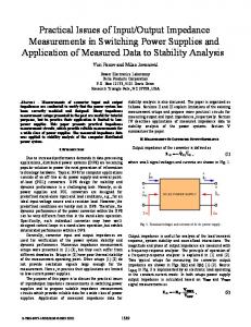
The schematic symbol of the CDTA is shown in
INDIAN J PURE & APPL PHYS, VOL 46, DECEMBER 2008
894
Fig. 1. The inputs p and n produce difference current which is transferred to the z terminal and the voltage at the z terminal is converted into a set of output currents by a dual output transconductance stage. The port relationships characterizing CDTA are given by Vp = Vn = 0, Iz = Ip – In, Ix = ± gVz where Vp, Vn and Vz represents the voltages at p, n and z terminals respectively. CDTA can be implemented using the bipolar transistors as shown in Fig. 2. The transistors T1-T11 forms the input stage, i.e. the current differencing circuit followed by a transconductance amplifier implemented by employing transistors T12-T24. The transconductance gain g of the CDTA is given by g=
IB 2VT
where IB is the bias current and VT ≅ 26 mV at a temperature of 27°C.
The proposed circuit is shown in Fig. 3. The analysis of the circuit yields the following transfer function: Io =
I 2 − I1 1 − sCR 1 + sCR
1 = 2 R , where g is the g transconductance gain of CDTA. When I1=Iin and I2=0,
with the realizability condition
Io 1 =− 1 − sCR I in 1 + sCR
When I2=Iin and I1=0, Io 1 = 1 − sCR I in 1 + sCR
The circuit thus provides both inverting and noninverting types of first-order AP inverse filters. 2.2 Non-ideal analysis
In non-ideal case, the CDTA can be characterized by the following port relations Vp=Vn=0, Iz=αpIp-αnIn, Ix=gVz Fig. 1 — Schematic symbol of CDTA
where αp =1-εp and εp(│εp│