frequency 270 MHz. This direct sampling method does not require a down-converter, and hence, the calibration step can be avoided. These results are analyzed ...
THP106
Proceedings of LINAC08, Victoria, BC, Canada
HIGH SPEED DATA ACQUISITION SYSTEM USING FPGA FOR LLRF MEASUREMENT AND CONTROL H. Katagiri, S. Fukuda, T. Matsumoto, T. Miura, S. Michizono, Y. Yano, M. Yoshida High Energy Accelerator Research Organization 1-1 Oho, Tsukuba, Ibaraki 305-0801, Japan Abstract Currently, FPGA (Field Programmable Gate Array) technology is being widely used for accelerator control owing to its fast digital processing capability. We have recently developed a high-speed data acquisition system that combines a commercial FPGA board (ML555) with a fast ADC (ADS5474; 14 bit; maximum sampling rate: 400 MS/s; bandwidth: 1.4 GHz). This system enables direct measurements of 1.3-GHz RF signals at a sampling frequency 270 MHz. This direct sampling method does not require a down-converter, and hence, the calibration step can be avoided. These results are analyzed and compared with those obtained with the conventional measurement method.
INTRODUCTION Plans for the construction of an STF (Superconducting RF Test Facility) for the ILC (International Linear Collider) are currently in progress [1,2]. An LLRF (Low Level RF) control system based on a compact PCI has been installed in the STF at KEK in order to achieve the required amplitude and phase stability (0.3% and 0.3°) during RF pulse (1300 MHz, 1.5 ms) generation [3]. A customized FPGA board, which is built into the PCI crate, conducts feedback and feedforward control. The amplitude and phase, measured using the intermediate frequency (IF) conversion method, have been adopted in the LLRF control system. An RF signal is converted into a 10-MHz IF signal using a down-converter. The FPGA board (equips 10 16-bit ADCs) samples the IF signal at a 40-MHz clock signal and calculates IQ elements for the collection of amplitude and phase data. Recently, a highspeed and wideband ADC, which that can sample RF signal directly, 1300 MHz RF signal is available. A highspeed data acquisition system using a fast ADC has been utilized for evaluating the efficiency of the direct sampling method.
ADS5474 ADS5474EVM is an evaluation board equipped with an ADS5474 ADC manufactured by Texas Instruments. Its features are as follows: • Resolution: 14 bit • Maximum sampling rate: 400MSPS • Analog bandwidth: 1.4 GHz • Data output: LVDS compatible
ML555 ML555 is a commercial FPGA board manufactured by Xilinx and is equipped with a Virtex-5 (XC5VLX50T). Its features are as follows: • PCI-Express/PCI/PCI-X card-edge connector • DDR2-SDRAM • LVDS interface with SAMTEC connector USB port
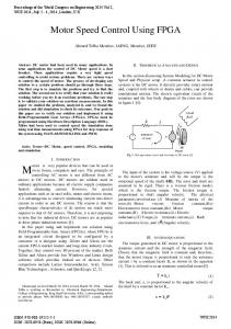
Figure 1: Block diagram of the high-speed data acquisition system.
CONSTRUCTION OF HIGH-SPEED DATA ACQUISITION SYSTEM The high-speed data acquiring system is composed of an ADC board (ADS5474EVM) and an FPGA board (ML555). The FPGA board stores the raw data acquired by the ADC board in its internal memory. This data is then transmitted and analyzed by the host PC (Fig.1). Figure 2 shows the ML555 installed in a PCI-Express slot on the host PC. ML555 and ADS5474EVM are connected by LVDS cables via adaptors, as shown in Fig.3.
Technology 1042
Figure 2: ML555 and ADS5474EVM on host PC.
Figure 3: SAMTEC connector adaptor. 3D - Low Level RF
Proceedings of LINAC08, Victoria, BC, Canada
THP106
Figure 4: Block diagram of the FPGA logic.
DESIGN OF FPGA LOGIC Figure 4 shows the construction of an FPGA logic. Xilinx ISE9.2, an integrated development tool, has been utilized for designing the FPGA logic.
LVDS Interface Virtex5 has input-buffers and output-buffers which can handle single-end signal and differential signals. ML555 is equipped with two SAMTEC connectors as the LVDS interface.
Data Acquisition and Storage A built-in memory block Virtex-5 has been used to accumulate the acquired data. A dual-port RAM (width: 14 bit; 131,072 words) designed by CoreGenerator is included in the designing software developed by Xilinx (ISE9.2). At a sampling frequency of 400 MHz, the memory block can accumulate data of around 327 μs. The data accumulation time is controlled by the external trigger signal.
Host Interface A USB-UART (Universal asynchronous receivertransmitter) bridge is equipped with ML555. ML555 has been identified to be connected with the serial port on the host computer upon installation of the bridge driver software. An asynchronous serial communication circuit, which was developed for another FPGA board, is used to reduce the development time. A communication program on the host PC is designed using LabVIEW. The entire data in the FPGA can be transferred in approximately 4 seconds.
EVALUATION OF DIRECT SAMPLING IN STF Direct Sampling Method The high-speed data acquisition system is applied to electric field measurement of the superconducting cavity in STF. The direct sampling method has the following advantages. Because a sampling clock is faster, events Technology
that cannot be acquired by the IF conversion method might be detected. Since a down-converter is unnecessary, construction of the RF measurement circuit becomes significantly simple. Moreover, measurement errors that depend on the characteristics of the down-converter will be eliminated. However, because the sampling frequency is lower than the RF frequency, it is necessary to obtain an average of the data accumulated over several cycles in order to calculate the IQ elements. Therefore, selection of proper sampling frequency is important. The clock divider and IQ modulator manufactured by Analog Devices were combined to distribute the clock signal to the data acquisition system. The frequency of the generated clock signal is calculated as follows:
f =
f ⎞ N +1 , 1 ⎛ f0 ⎜ f0 + 0 ⎟ = M⎝ N ⎠ MN
(1)
where f0 is the input frequency (1.3GHz), and M and N are parameters of the frequency divider. The data acquired in this method can be separated into I and Q elements by the following expressions [4,5]: I=
2 L ⎛ 2π M N ⎞ ∑ x(k ) × cos⎜⎝ N + 1 k ⎟⎠ L K =1
(2)
Q=
2 L ⎛ 2π M N ∑ x(k ) × sin⎜⎝ N + 1 L K =1
(3)
⎞ k⎟ ⎠
The chosen parameters are M = 24, and N = 5 (sampling frequency: 270.83 MHz). In this case, the RF signal is sampled five times over 24 cycles.
Results The RF output signal obtained from the STF superconducting cavity was measured by the fast data acquisition system. Figure 5 shows the raw data recorded during the rising of the pulse signal using LabVIEW. The memory capacity of the FPGA was insufficient for acquiring the complete pulse width at 270.83 MHz. Hence, the measurements were repeated six times by adjusting the trigger time. 3D - Low Level RF 1043
THP106
Proceedings of LINAC08, Victoria, BC, Canada
REFERENCES
Figure 5: Amplitude and phase data obtained from direct sampling method.
[1] “ILC Reference Design Report (RDR),” http://www.linearcollider.org/cms/?pid=1000437. [2] S. Fukuda et al., “Status of RF Sources in Superconducting RF Test Facility (STF) at KEK,” Linac08. [3] S. Michizono et al., “Performance of Digital LLRF system for STF in KEK,” Linac08. [4] T. Matsumoto et al., “Performance of Digital LowLevel RF Control System with Four Intermediate Frequencies,” Linac08. [5] T. Matsumoto et al., “Low-level RF System for STF,” Linac06, Knoxville, Aug 2006, p.586.
Figure 6: Amplitude and phase data obtained from direct sampling method.
Figure 7: Amplitude and phase measured by IF convert method. Figure 6 shows the amplitude and phase data of the complete pulse width converted by MATLAB. Though the reference point of the phase was different for each measurement, it was stable within the given range for a single measurement. The amplitude and phase data obtained using the conventional IF conversion method are shown in Fig. 7. It is confirmed that the results of the direct conversion method agree well with those obtained with the conventional data acquisition system.
CONCLUSION A high-speed data acquisition system comprising ML555 and ADS5474 was employed to measure RF signals in STF by the direct sampling method. The effectiveness of this method was confirmed by verifying results of the measurement.
Technology 1044
3D - Low Level RF