Image Compression by Visual Pattern Vector Quantization (VPVQ) ... the decoder must use the same down-sampling in order to achieve better quality by VQ.
Data Compression Conference
Image Compression by Visual Pattern Vector Quantization (VPVQ) Feng Wu, Xiaoyan Sun Microsoft Research Asia, Beijing, China {fengwu, xysun}@microsoft.com Abstract This paper proposes a new image compression scheme by introducing visual patterns to nonlinear interpolative vector quantization (IVQ). Input images are first distorted by a generic down-sampling so that some details are removed before compression. Then, the distorted images are compressed lossly by traditional image coding scheme and transmitted to the decoder. In the decoder side, VQ indices are extracted from the decoded images to reproduce the removed details from a pre-trained codebook. One of main contributions in this paper is, we introduce visual patterns on designing the codebook, where only removed details that contain visual patterns and their original counterparts as pairs are trained. Experimental results show: (1) visual pattern blocks are easy to form clusters than original blocks; (2) the proposed scheme achieves much better performance over JPEG in terms of visual quality and PSNR.
1. Introduction There are two different kinds of quantization for data compression: scalar quantization (SQ) and vector quantization (VQ). Shannon’s rate-distortion theory indicates that better performance can be achieved by coding vectors instead of scalars [1]. Linda, Buzo and Gray (LBG) first proposed an iterative vector quantizer design algorithm by using clustering approach [2]. Although the LBG is very general, it does not consider the structure properties of source and output, thus suffering from high complexity on memory and computation. A class of product code VQ is proposed to reduce memory and computation through structural constraints, where different attributes or features of outputs are processed by different components of the VQ quantizer [3]~[5]. Another class of VQ is so-called residual vector quantizers, where residual error of one stage quantizer is iteratively fed into next stage quantizer [6]~[8]. Interpolative vector quantization, first proposed explicitly by Gersho in [9], introduces dimension reduction to traditional VQ. The codebook in the encoder is learned on downsampled vectors and the codebook in the decoder on high-dimension vectors. Except for the difference on dimension, the two codebooks have the same number of representative vectors and structure. VQ encoder maps down-sampled inputs to a set of scalar indices and VQ decoder reproduces high-dimension inputs by received indices. David et al. applied IVQ to image restoration [10], where the encoder does not need a codebook except for some parameters. The codebook at the decoder is learned on image pairs consisting of an original image and its diffraction-limited counterpart. Several follow-up work is reported in [11][12]. But all these techniques directly operate on image blocks. This paper proposes a new image compression scheme by introducing visual patterns into IVQ. It is well recognized that down-sampling and up-sampling process will considerably hurt salient (e.g., edge and contour) regions and make them blur. On the contrary, it has few effects on flat regions. Therefore, this paper mainly considers how to handle edge regions by VQ. Visual pattern is proposed to characterize intensity variation and its geometry around
1068-0314/08 $25.00 © 2008 IEEE DOI 10.1109/DCC.2008.35
123
edges. It is generated by removing low-frequency part from an image block that contains large intensity variation. The proposed VQ is designed to reproduce the information of visual patterns removed by down-sampling. The rest of this paper is organized as follows. In Section 2, we will give an overview of the proposed image compression scheme. Some key techniques of the proposed scheme are discussed in Sections 3~5. The experimental results demonstrate the advantages of the proposed scheme in Section 6. Finally, Section 7 concludes this paper.
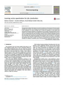
2. The proposed image coding scheme The proposed image compression scheme is illustrated in Figure 1, where the left dash-line box is the proposed encoder and the right is the proposed decoder. In the encoder side, input image is first down-sampled by a low-pass filter. The downsampled image can be compressed easily because it has fewer pixels and some details have been removed by the down-sampling filter too. In the proposed scheme, a generic distortion method is adopted for down-sampling and up-sampling. It supports different sub-lattices and different filters. Similar to [10], the proposed scheme does not need a codebook in the encoder side either. But the proposed encoder has to know which kind of down-sampling is used and what the parameters are in the training process to generate codebook. The encoder and the decoder must use the same down-sampling in order to achieve better quality by VQ. The down-sampled image is usually compressed lossly by traditional image coding scheme such as JPEG or JPEG 2000 and is transmitted to the decoder. Besides the distortion introduced by compression, the key problem is to reproduce the details removed by down-sampling. Unlike other IVQ schemes (e.g. [9] and [10]), where the codebook is designed to recover high-dimension image directly from down-sampled image, the proposed VPVQ tries to recover intensity variations only in salient regions, namely, the so-called visual patterns, by a codebook. Therefore, in the proposed visual pattern codebook, each item consists of two codewords. One is for blurred visual pattern and another is for highquality visual pattern. In the decode side, the decoded image is first up-sampled to the original resolution and then edges are detected from the up-sampled image. After high-pass filtering, blurred visual patterns are extracted from the up-sampled image according to the locations indicated by edge pixels. Those blurred visual pattern blocks are used as vector indices to find the corresponding high-quality visual patterns from the pre-trained codebook. Finally, the decoded image and retrieved visual patterns are blended together to reproduce input image.
Image
Down Sampling
Distorted Parameters
Image Encoder
Image Decoder
Index Generation
Blending
Restored Image
Vector Indices Visual Pattern Codebook
Figure 1: The proposed image compression scheme. There may be two different opinions to the proposed scheme. One is that the proposed is a scheme for image restoration, which consists of the modules of index generation, codebook and blending. Another is that the proposed is a VQ scheme for image compression. In the
124
encoder side, input high-dimension vectors are first quantized to low-dimension vectors although the down-sampling is not optimum for this purpose. Then, we do not assign an index for each input vector. Instead, we directly compress low-dimension vectors lossly and transmit them to the decoder. In the decoder side, vector indices are generated from the decoded low-dimension vector to find the corresponding high-dimension vector. The key point to distinguish these two opinions is whether the modules of index generation, codebook and blending are independent on the previous modules of Figure 1 because image restoration should be transparent to the previous processing. In the proposed scheme, the index generation and down-sampling modules have to be coupled together for better performance. We also note that visual features are also considered on designing traditional VQs in [13][14] before this paper. But the proposed scheme is significantly different from them. The details of each process are discussed in the following sections.
3. Generic distortion In this paper, the generic distortion is described by the group theoretic approach. We define an N-dimensional sampling lattice L as a sub-lattice L ⊂ ℤN of rank N. The generating matrix of the lattice L is a nonsingular N × N integer matrix G so that the map of any t ∈ ℤN ⟶ Gt ∈ ℤN is exactly the lattice L. In 2-D cases, the matrix G can be written as a Hermitian upper triangular form 0 � � (1) �=� 1
�. 0 �2 0 �1 and �2 are positive real units in each dimension, respectively. �, ��� are integers with the constraints �, ≥ 1 and 0 < ≤ �. Once G is selected, the generic down-sampling and filtering yields the down-sampled signal x�[Gt] by ��[��] = � �[�]ℎ1 [�� − �], ��� �� ∈ �1 .
(2)
�∈�0
Here we assume the lattice �1 is the sub-lattice of �0 , where � is the generating matrix from �0 to �1 . �1 = {ℎ1 [⋅]} is the down-sampling filter with limited support. �[�] is the input high-resolution signal. The corresponding up-sampling and filtering operation results in ��[�] = � ��[��]ℎ2 [� − ��] .
(3)
��∈�1
�2 = {ℎ2 [⋅]} is the down-sampling filter with limited support. ��[�] is the up-sampled signal that has the same resolution as input. The distortion parameters include the sampling matrices and the down-sampled filter. In general, the operators (2) and (3) do not affect flat regions of input image too much in terms of visual quality. However, salient regions especially around edges and contours will be blurred significantly.
4. Visual pattern The concept of visual pattern is inspired by primal sketch. It is the description of intensity variations in images and their local geometries in the Marr’s vision theory [15]. It not only contains intensity variations but also implicates geometric edge information. Recent studies show that using primal sketch priors can significantly improve the visual quality of image hallucination [16]. The proposed visual pattern is the feature which mainly characterizes the variation in primal patches without taking the magnitude of intensity into account. In order to get highquality visual patterns, the residual signal is first calculated as
125
�[�] = �[�] − ��[�]. (4) In order to further remove the effects of low-frequency part, the residues are decomposed into two parts, namely, normalized part �[�] and scaling part ![�] �[�] �[�] = , (5) ![�] "ℎ#�# ![�] = � |�[$]|ℎ3 [� − $]. $∈%1
�3 = {ℎ3 [⋅]} is the normalized low-pass filter and %1 is a window. And all edge pixels {ei }, i = 1, … , M, are extracted from x�′[t], which is the decoded version of x�[t]. They are same if the lossless compression is applied. But, in this paper, since the lossy compression is adopted, they are different. The high-quality visual pattern block P is extracted from p[t] by (6) & = '�[�]*� ∈ +, �0 ∈ +, �0 ∈ {-/ }6. + is a NxN block and �0 is the center of the block. In other words, the central pixel of a visual pattern block must be an edge pixel. The blurred visual pattern block P′ is also extracted by the same way (5) and (6). But the signal r[t] is replaced by � ′ [�] = �� ′ [�] − � �� ′ [$]ℎ4 [� − $] .
(7)
$∈%2
�4 = {ℎ4 [⋅]} is the low-pass filter and %2 is a window. Equation (7) is actually the highpass filtering. The extracted &′ should be similar to & but is blurred. This similarity is just our motivation to design the proposed VPVQ. By taking the corresponding pairs of visual pattern blocks, a codebook can be generated by the clustering method.
5. The proposed VPVQ 5.1 Codebook design Let 'Pi , P′ i 6, i = 1, … , M, be a sequence of visual pattern block pairs, where Pi and P′i are high-quality visual pattern block and blurred visual pattern block, respectively. Obviously, the general approach should be to optimize the partition cells of Pi and P′i simultaneously. For simplicity, the proposed codebook is designed on optimizing the partition cells of Pi , namely, minimizing the distortion 9:; = �
C
@=1
�
�AA &/ ∈B@
‖&/ − ?@ ‖�(&/ ) .
(8)
Here assume that all &/ are mapped to one of K output vectors ?@ and B@ denotes the k-th partition cell. ‖⋅‖ is the Euclidean or A2 norm. �() is the joint probability mass function of &/ . The codeword ?@ is calculated by the nearest neighboring principle ?@ = &/ , !. E. min
&/ ∈B@
� F&H − &/ F.
(9)
�AA &H ∈B@
Once the partition cells are decided, we also apply the partition cells to &′/ and calculate the codeword ?′@ corresponding to &′/ (10) ?′@ = &′/ , /� ?@ = &/ . ′ Therefore, each item in the proposed codebook is a pair '?@ , ? $ 6. 5.2 Reconstruction In the decoder side, we first decode the received stream and get the reconstructed downsampled x�′[t]. The up-sampled signal x�′[t] is calculated from x�′[t] by (3). Then, according to
126
Equations (7), (5) and (6), blur visual pattern blocks P′ can be generated. For each blurred visual pattern block, the location k in the codebook can be found by minimizing (11) minF&′ − ?′@ F. @
Therefore, we have the high-quality visual pattern Ck . The final reconstruction should be �[�] = �� ′ [�] + �̃ ′[�]. "/Eℎ �̃ ′[�] = R � ?@ [�] ! ′ [�].
(12)
�AA ?@ [�]
In the proposed scheme, one pixel may be enhanced by multiple high-quality visual pattern blocks. ?@ [�] means that the retrieved visual pattern blocks cover the location �. !′[�] is the scaling information calculated from �′[�]. R is an empirical constant to compensate the energy difference between !′[�] and ![�].
6. Experimental results The experiments are designed to evaluate the performance of the proposed image coding scheme. In this paper, we only pay our attention on luminance component of image. The filters used in this paper are listed here. H1 is 5-tap Gaussian filter, H2 is 4-tap cubic filter, H3 is 13-tap low-pass filter and H4 is 7-tap unit filter. 6.1 Signal generation We first take JPEG test image Lena 256x256 to demonstrate the signals generated in the proposed scheme and exhibit their relationship. The down-sampling ratio is set as 2:1 at orthogonal lattice. In this experiment, the down-sampled image is assumed to code losslessly so that the best performance of the proposed VPVQ can be evaluated. All signals are depicted in Figure 2. In Figure 2, the left side of the first row is p[t] generated by (4) and (5), and the left side of the second row is s[t]. The corresponding right sides of the first and second rows are p′[t] and s′[t] generated by (7) and (5), respectively. One can observe that s[t] and s′[t] are very similar except for a bit difference feeling on lightness. Therefore, we can use s′[t] to replace s[t] during the reconstruction after it is compensated by an empirical constant. p[t] and p′[t] are also very similar. But p[t] has more details in edge and contour regions that are removed by down-sampling. The proposed VPVQ is designed to recover p[t] from p′[t]. The left side of the third row is the edges extracted from the up-sampled image by different directional filters. They indicate the regions that have big differences between p[t] and p′[t]. The proposed visual pattern blocks are extracted around these edge pixels and enhanced by the proposed codebook. Finally, the right side of the third row is the reconstructed �̃ ′[t], which is generated by equation (12). Compared with p′[t], the reconstructed �̃ ′[t] is greatly enhanced by the details in edge and contour regions. 6.2 Training set In this paper, all 25 Kodak images with the size 768x512 or 1536x1024 are selected as the training set. For the proposed VPVQ, it is not important which images are selected as the training set because what we will learn are visual pattern blocks. The important is that these selected images should contain rich visual patterns. In this paper, the size of each visual pattern block is 9 by 9. The blurred visual pattern blocks are not compressed in the training process so as to avoid quantization distortion in the codebook although it exists in the decoding process.
127
Figure 2: The signals generated in the proposed scheme by taking Lena as an example (�[�] and �′[�] in the first row; s[�] and !′[�] in the second row; the edge in the left side of the third row and the reconstructed �̂ ′[�] in the right side). The extracted visual pattern blocks are exemplified in Figure 3, which has 200 blurred visual pattern blocks and their corresponding high-quality visual pattern blocks. One can observe that visual pattern blocks are much simple and only present intensity variations. The blurred visual pattern blocks present the similar variation but are much blur.
128
Figure 3: The exemplified high-quality visual patterns from �[E] (left side) and the corresponding blurred visual patterns from �′[E] (right side). One experiment is designed to verify the sparseness of the proposed visual pattern blocks. The clustering method in this paper is the enhanced LBG (ELBG) [17]. ELBG is an enhanced version of LBG algorithm, which uses the concept of utility of a codeword to avoid a bad choice of the initial codebook. 82567 pairs of visual pattern blocks extracted from the first two images of our training set are used in this experiment. We also extract the blocks according to the same edge information directly from original images just like traditional IVQ. Both sets of data are input to the ELBG method by specifying different numbers of codewords. The curves of MSE vs. the number of codewords for both sets are depicted in Figure 4. The horizontal coordinate is the number of codewords and the vertical is MSE. One can observe that, for the same input vectors and codewords, visual pattern blocks are easier to form clusters.
MSE vs Num of Codewords
350
MSE
300
Visual Pattern
250
Image block
200 150 100 50 0 0
10000
20000
30000
40000
Figure 4: The curves of MSE vs. number of codebooks for comparisons between visual pattern blocks and image blocks. 6.3 Performance Finally, we will compare the proposed scheme over JPEG in terms of visual quality and PSNR at low bit rates. In the proposed scheme, Lena 512x512 is down-sampled 3:1 in each dimension and is compressed by JPEG at 1.665bpp. Since the down-sampled image is only one-ninth of the original number of pixels, it is equivalent to compress the original image at 0.185bpp in terms of rate. The edges are extracted from the decoded and up-sampled image. They are similar as that shown in Figure 2 and small differences are caused by JPEG compression. The total number of visual pattern blocks is 16710. The final reconstruction by the proposed scheme is depicted in Figure 5. Although the bit rate is very low, the visual quality is good and its PSNR is about 29.92dB. If the input image is directly compressed by JPEG at 0.185bpp, the reconstructed image is also depicted in Figure 5. It has a lot of block artifacts and its PSNR is only 28.24dB.
129
Figure 5: The reconstructed images at 0.185bpp (left side: the proposed scheme; right side: JPEG).
8. Conclusions This paper proposes an image compression scheme by introducing visual pattern into IVQ. The removed details in silent regions by down-sampling are reproduced by the proposed VPVQ. Experimental results fully demonstrate the advantages of the proposed techniques and the overall performance. It can even outperform JPEG more than 1.7dB. More significantly, the visual quality of reconstructed image in the proposed scheme is very good even at very low bit rates. Furthermore, the proposed VPVQ also presents some advantages that do not exist in other VQ schemes. First, unlike traditional vector quantization, the proposed VPVQ neither compresses scalar indices nor transmits them to the decoder. Instead, the down-sampled image is compressed lossly by traditional image coding scheme and transmitted to the decoder. The vector indices are finally extracted in the decoder from the decoded down-sampled image. Second, the similarity between blurred visual pattern blocks and high-quality visual pattern blocks are utilized to find proper codewords in the codebook. Although the lossy compression may make blurred visual pattern blocks different at the encoder and the decoder, as long as the similarity is reserved, the reconstructed quality is still acceptable. Third, the proposed VPVQ potentially allows different training sets used in different decoders because the indexing method in this paper does not request the exact same codebook. There are still many aspects to be investigated in the future, such as adaptive up-sampling, enhanced indexing method, large-scale visual pattern learning, and so on.
Acknowledgement The authors are grateful to Dr. Heung-Yeung Shum and Dr. Jian Sun for their valuable discussions, and thank Professor Chang Wen Cheng and Ming-Ting Sun for their helpful suggestions.
130
References [1] C. E. Shannon, “A mathematical theory of communication,” Bell System Tech. Journal, vol. 27, pp. 379-423, 623-656, 1948. [2] Y. Linde, A. Buzo, R. M. Gray, “An algorithm for vector quantizer design,”, IEEE trans. Communication Technology, vol. COM-28, pp. 84-95, 1980. [3] R. L. Baker, R. M. Gray, “Differential vector quantization of achromatic imagery,” Picture Coding Symposium, pp 105-106, 1983. [4] M. J. Sabin, R. M. Gray, “Product code vector quantizers for waveform and voice coding,” IEEE trans. ASSP, vol. 32, pp. 474-488, 1984. [5] K. L. Oehler and R. M. Gray, “Mean-gain-shape vector quantization,” International Conference, on ASSP, vol. V, pp. 241-244, 1993. [6] C. F. Barnes, S. A. Rizvi, N. M. Nasrabadi, “Advances in residual vector quantization: A review,” IEEE trans. Image Processing, vol. 3, pp 226-262, 1996. [7] B. H. Juang, A. H. Gray, “Multiple stage vector quantization for speech coding,” International conference Acoustic, Speech, Signal Processing, vol. 1, pp597-600, 1982. [8] J. Makhoul, S. Roucos, H. Gish, “Vector quantization in speech coding,” Proceeding of IEEE, vol. 73, pp. 1551-1588, 1985. [9] Gersho, “Optimal nonlinear interpolative vector quantization”, IEEE trans. on communication, vol. 38, pp 1285-1287, 1990. [10] D. G. Sheppard, A. Bilgin, M. S. Nadar, B. R. Hunt, M. W. Marcellin, “A vector quantization for image restoration”, IEEE trans. on Image Processing, vol. 7, pp119-124, 1998. [11] R. Nakagaki, A. K. Katsaggelos, “A VQ-based blind image restoration algorithm”, IEEE trans. on Image Processing, vol. 12, pp 1044-1053, 2003. [12] Y. C. Liaw, W. Lo, Z. C. Lai, “Image restoration of compressed image using classified vector quantization”, Pattern Recognition, vol. 35, pp329-340, 2002. [13] G. Qiu, M. R. Varley, T. J. Terrell, “Image coding based on visual vector quantization,” IEE International Conference on Image Processing and its applications, pp. 301-305, July 1995. [14] Ramamurthi, A. Gersho, “Classified vector quantization of images,” IEEE trans. on Communications, vol. 34, pp. 1105-1115, 1986. [15] Marr, “Vision: a computational investigation into the human representation and processing of visual information,” W. H. Freeman Publ., 1982. [16] J. Sun, N. N. Zheng, H. Tao, H. Y. Shum, “Image hallucination with primal sketch priors,” International Conference on Computer Vision and Pattern Recognition, vol. 2, pp. 729-736, 2003. [17] G. Patane, M. Russo, ‘The enhanced LBG algorithm,” Neural Networks, vol. 14, pp 1219-1237, 2001.
131