by-link, whose bandwidths are dedicated to GMPLS-UNI paths. (Fig. 3(b)) and whose .... The BoD server gathers the required bandwidth from the parallel links ...
This full text paper was peer reviewed at the direction of IEEE Communications Society subject matter experts for publication in the IEEE ICC 2009 proceedings
Implementation and Evaluation of Layer-1 Bandwidth-on-Demand Capabilities in SINET3 Shigeo Urushidani, Kensuke Fukuda, Yusheng Ji, Michihiro Koibuchi, Shunji Abe, Motonori Nakamura, and Shigeki Yamada National Institute of Informatics (NII) 2-1-2 Hitotsubashi, Chiyoda-ku, Tokyo, 101-8430 Japan
Kaori Shimizu, Rie Hayashi, Ichiro Inoue, and Kohei Shiomoto NTT Network Service Systems Laboratories 3-9-11 Midori-cho, Musashino-shi, Tokyo, 180-8585 Japan
Hiroyuki Tanuma NEC Corporation 1131 Hinode, Abiko-shi, Chiba, 270-1198 Japan Abstract—This paper describes the implementation and evaluation of layer-1 bandwidth-on-demand (BoD) capabilities in the Japanese academic backbone network, called SINET3. The network has a nationwide GMPLS-based layer-1 platform and provides reservation-based and signaling-based BoD services. The overall architecture for providing BoD services including its capabilities, user interface, path calculation, and interface to drive the layer-1 platform are described. Actual examples of BoD services and evaluations of the path setup/release time in the network are also presented. Keywords— bandwidth-on-demand; multilayer; GMPLS; nextgeneration SDH/SONET
I.
INTRODUCTION
Bandwidth-on-demand (BoD) capabilities have become increasingly important for academic networks [1]-[3] that support scientific research in which huge amounts of data have to be securely transmitted. For example, projects such as the eVLBI project [5] and one on non-compressed high-definition video communication [6] need assured end-to-end bandwidths between sites: the former needs about 2 Gbps (8 Gbps in the very near future), and the latter needs about 1.5 Gbps. Many research areas need large end-to-end bandwidths to back up their experimental data on a regular basis between home and remote sites. Moreover, network applications should not be affected when certain applications transfer huge amounts of data. The Japanese academic backbone network, SINET3, started to provide layer-1 BoD services in February 2008. SINET3 uses layer-1 technologies that completely separate the bandwidth for BoD services from other network services and provide an excellent transfer performance, such as low delay, no delay variance, and no packet loss. It accommodates these layer-1 services on the same network platform as the IP and Ethernet services in order to flexibly assign the network resource to each layer service. In our previous papers [3]-[4], we described the basic architecture of SINET3 for providing BoD services and its flexible resource assignment schemes,
and evaluated them within experimental environments. We have refined the architecture towards a full-scale operation, studied actual implementations of the BoD server, and evaluated the setup/release times in the actual network. The detailed implementation and evaluation of layer-1 BoD capabilities in SINET3 are presented in this paper. The remainder of this paper is organized as follows. Section II describes the general architecture for providing BoD services. Section III shows the screens for a path reservation and describes the path calculation algorithms for some given conditions. Section IV describes the interface between the BoD server and the layer-1 platform. Section V describes how BoD services are actually being used and evaluates the path setup/release time. Section VI is our conclusion. II.
LAYER-1 BOD SERVICES ARCHITECTURE
A. SINET3 Network Architecture SINET3 has a layer-1 network platform on which multilayer services are accommodated by using IP/MPLS and layer-2 multiplexing functions as well as layer-1 functions (Fig. 1). IP services, such as IPv4/IPv6 dual and IP-VPN, and Ethernet services, such as L2-VPN and VPLS, are provided over Ethernet-family interfaces. IP packets and Ethernet frames are multiplexed on layer-2 by using internal VLAN tags and accommodated onto a layer-1 path whose bandwidth is a multiple of VC-4 (about 150 Mbps) between the edge and core layer-1 switches by using general framing procedure (GFP) [7] and virtual concatenation (VCAT) functions [8]. The layer-1 path for IP/Ethernet services leads to an IP router, where each service packet/frame is identified by its VLAN tag and distributed to the corresponding logical router for each service. Here, the IP-VPN, L2-VPN, and VPLS packets/frames are encapsulated with MPLS labels in each logical router. Layer-1 services are provided over both Ethernet-family and SDH/SONET-family interfaces. The data of each interface are accommodated onto an individual end-to-end layer-1 path between edge layer-1 switches. The setup and release of the
978-1-4244-3435-0/09/$25.00 ©2009 IEEE
This full text paper was peer reviewed at the direction of IEEE Communications Society subject matter experts for publication in the IEEE ICC 2009 proceedings
data IP Ether
L3 IP Router data
Ether
L2 MUX
Flow Control (IEEE802.3x) 10GE
Hitless Bandwidth Change by LCAS
IP Router
Ethernet Switch
Layer-1 BoD Server
HTTP(S)
CORBA
IPv4/IPv6 IPVPN
IP/Ethernet Traffic
BoD Users
Leading-edge GE/10GE/2.4G Device
: Logical Router
Core L1 Switch
L1SW
IP/MPLS Traffic Ethernet
: Logical Router (MPLS)
40/10 Gbps (SDH)
As the network accommodates a single path for IP/Ethernet services and several paths for layer-1 services onto the same physical line, it changes the path bandwidth for the IP/Ethernet services when we need more bandwidth for the layer-1 services. The path bandwidth can be hitlessly changed by using the link capacity adjustment scheme (LCAS) [9] with a VC-4 granularity. In addition, to shape the traffic burst of IP/Ethernet services into the assigned path bandwidth, a back pressure mechanism using PAUSE frames compliant with IEEE802.3x is used between a layer-1 switch and an IP router (also between a layer-1 switch and a layer-2 multiplexing). B. BoD Services General Architecture A layer-1 BoD server, developed by NII, plays an important role in providing BoD services by controlling the layer-1 network platform (Fig. 2). SINET3 provides two types of BoD services, reservation-based and signalling-based, in the following way. For the reservation-based services, the BoD server receives users’ requests, such as destinations, duration, bandwidth, route preference, and redundancy, through the Web screens. It calculates the appropriate routes, i.e. transit nodes and links, depending on route preferences, such as minimum end-to-end delay, maximum available bandwidth, and redundancy. After admission control and scheduling, the BoD server drives the operation system of the layer-1 switches (L1-OPS) to direct the source layer-1 switch to establish a layer-1 path toward the destination by using the GMPLS RSVP-TE protocol [10], [11]. The BoD server also drives L1-OPS when we need to change the path bandwidth for the IP/Ethernet services. For signaling-based services, the BoD server preliminarily establishes forwarding adjacency (FA) paths on which the GMPLS-UNI paths should be established (as described in Sec. IV. D). After a GMPLS-UNI path is established between the edge layer-1 switches by GMPLS-UNI signalling from a user, the BoD server receives a notification message from L1-OPS and checks whether the path is set up along the assigned FA paths. When the route of the GMPLS-UNI path is along the assigned FA paths, the BoD server registers the path information in its database. If not, it forcibly releases the GMPLS-UNI path. The interface between the BoD server and L1-OPS is based on CORBA, which is compliant with TMF-814 [16], and that
Resource management
TL1
GMPLS (RSVP-TE L1SW and OSPF-TE)
L1SW
L1SW
L2 MUX
L2 MUX
IP
Hitless Bandwidth Change by LCAS IP Router
Figure 1. Network architecture of SINET3.
layer-1 paths among the layer-1 switches are dynamically performed by using GMPLS protocols [10]-[14].
Path calculation
Path & bandwidth control
GMPLS Control and Management Plane
10/2.4 Gbps (SDH) Edge L1 Switch
Admission control & Scheduling
L1-OPS
Static or GMPLS-UNI
L2VPN VPLS
L1 Traffic
L2
L1
Destinations, Duration, Bandwidth, Route preference, and Redundancy
GMPLS Control and Management Plane FE/GE/10GE
Front-end
User Equipment
IP Router
Figure 2. General architecture for BoD services. Edge L1SW
Edge L1SW
Edge L1SW
Edge L1SW
Working FA Path Core L1SW
Core L1SW
Core L1SW
Core L1SW
Core L1SW
Core L1SW
Core L1SW
Core L1SW
Core L1SW
Core L1SW
Core L1SW
Core L1SW
Protection FA Path Edge L1SW
(a) For redundant paths.
Edge L1SW
FA Paths for GMPLS-UNI Edge L1SW
Edge L1SW
(b) For GMPLS-UNI paths.
Figure 3. Use of FA paths for redundancy and GMPLS-UNI.
between L1-OPS and the layer-1 switches is based on TL1. More details are given in Secs. III and IV. C. Traffic Engineering using FA Paths We use FA paths for two purposes. One is for creating redundant paths and the other is for accommodating GMPLSUNI paths. For the former, SINET3 will use LSP rerouting functions [13] for mission critical applications and important demonstrations. We set up a working FA path between the trunk sides of specified layer-1 switches and at the same time register the information for the protection FA path between them (Fig. 3(a)). The protection FA path is established after the working FA path encounters a network failure. Layer-1 paths accommodated onto the working FA path are then rerouted to the protection path. For the latter, we use FA paths to enable the layer-1 switches to identify the network resources assigned to GMPLS-UNI paths. We preliminarily set up FA paths linkby-link, whose bandwidths are dedicated to GMPLS-UNI paths (Fig. 3(b)) and whose metric values are smaller than those of physical links. Because each layer-1 switch exchanges the link state information for all links including the FA paths by using GMPLS OSPF-TE protocol [12] and calculates the route for a GMPLS-UNI path by treating the FA paths in the same way as the physical links, the route is always along the FA paths. III.
CAPABILITIES OF BOD SERVER
A. User Interface for Reservation-based Services For the reservation-based service, a user accesses simple web pages (Fig. 4(a)–(d)) to submit the parameters for layer-1 paths. After selecting the connection style from between the VPN and Extranet, the user chooses the source and destination
This full text paper was peer reviewed at the direction of IEEE Communications Society subject matter experts for publication in the IEEE ICC 2009 proceedings
Kyushu Univ. L1SW
Doshisha Univ. L1SW
Yamaguchi
Univ. L1SW
Hokkaido
: Edge L1SW
Univ. L1SW
: Core L1SW
(a)
Fukuoka L1SW
4 ms
Hiroshima
L1SW
5 ms
6 ms
Kyoto L1SW
12 ms
Kanazawa
Sapporo L1SW
L1SW
7 ms 4 ms
Tokyo2 L1SW
3 ms
7 ms
1 ms
(b)
Matsuyama
5 ms
L1SW
2 ms Osaka Osaka L1SW-2 L1SW-1
Osaka Univ. L1SW
Tokyo1 L1SW-3
3 ms Nagoya Nagoya L1SW-1 L1SW-2
NIFS L1SW
Tokyo1 L1SW-1
Tokyo1 L1SW-2
NAOJ L1SW
NII L1SW
3 ms
Tsukuba L1SW
5 ms
Sendai L1SW
KEK L1SW
Figure 5. Core switches and edge switches accommodating BoD users.
(c)
doesn’t select parallel links in order to easily find a disjoint protection FA path candidate against a working FA path. As the Tokyo1, Nagoya, and Osaka nodes are composed of multiple layer-1 switches, the BoD server first calculates the end-to-end route by regarding the combined layer-1 switches as a single virtual layer-1 switch, as shown by the dashed-line boxes in Fig. 5, and next calculates the shortest internal routes of each node.
(d)
Figure 4. Sample reservation screens.
nodes (Fig. 4(a)) and the duration (Fig. 4(b)) from the pulldown menu. On the next page (Fig. 4(c)), the BoD server calculates and then shows the available bandwidths and rough delays between specified nodes. By referring to them, the user can choose the source and destination ports, the bandwidth (lambda that provides the full bandwidth of the physical interface or multiples of 150 Mbps), and the route preferences (minimum delay route; the same route constraint for multiple paths). For mission critical projects, they can find check boxes for requesting protection paths. Figure 4(d) shows the page for confirming a reservation.
IV.
INTERFACE BETWEEN BOD SERVER AND L1-OPS
We developed a CORBA interface compliant with TMF814 [16] between the BoD server and L1-OPS. The supported operations between them are createSNC, deleteSNC, getSNC, getRoute, changeSNCBandwidth, retrieveSwitchData, and getAllCurrentPMData. Notification messages from L1-OPS to the BoD server are used to notify the completion of operations.
B. Path Calculation Figure 5 shows the core layer-1 switches (16 switches) and edge layer-1 switches (8 of 63 switches) that presently accommodate actual BoD users. The BoD server calculates the appropriate routes depending on the route preferences it receives. The BoD server finds the minimum delay route by using the Dijkstra algorithm, which uses the delay of each link as the link metric. When the minimum delay route is not specified, it finds the route that has the maximum available end-to-end bandwidth. This route is determined by using the Edmonds-Karp algorithm [15], which uses the available bandwidth for the layer-1 services of each link, as the link metric, and finds the shortest route with the maximum available end-to-end bandwidth.
A. Layer-1 Path Setup and Release The BoD server uses createSNC to request L1-OPS to create a layer-1 path (Fig. 6). The createSNC parameters include the path name, route information, and bandwidth. Upon receipt of a request (createSNC REQ), L1-OPS registers the path information in the source layer-1 switch, requests the switch to set up a layer-1 path, and sends the BoD server a response (createSNC RESP). When the path setup between the source and destination layer-1 switches is completed, L1-OPS receives a completion notice from the source layer-1 switch, retrieves the path information for confirmation, and notifies the BoD server of the completion of the path creation by sending a notification message (notification (create CMPLD)). Then, the BoD server uses getSNC to check the end-to-end path status, such as the J1 path trace result. When we create a layer-1 path composed of diverse sub-paths, the BoD server establishes the first sub-path and then adds additional sub-paths to it by using createSNC, which includes the same path name. It can also use createSNC to hitlessly increase the bandwidth of the already established layer-1 path.
The BoD server gathers the required bandwidth from the parallel links between the layer-1 switches to enable the remaining bandwidth for the IP/Ethernet services of each link to be as balanced as possible, thereby maximizing the packet forwarding performance. For LSP rerouting, the BoD server
For path deletion, the BoD server uses deleteSNC, whose parameters include the path name. The BoD server sends a deleteSNC REQ to L1-OPS and receives a deleteSNC RESP followed by a notification (delete CMPLD) of the completion of the path deletion from L1-OPS. For getting the traffic data
This full text paper was peer reviewed at the direction of IEEE Communications Society subject matter experts for publication in the IEEE ICC 2009 proceedings
L1-BoD Server
L1-OPS createSNC REQ (L1)
L1-BoD Server
L1SW
L1-OPS
createSNC REQ (FA, working)
Path registration REQ (L1) Path registration RESP (L1)
Path registration REQ (FA, w) Path registration RESP (FA, w) Path setup REQ (FA, w)
Path setup REQ (L1) Path setup RESP (L1)
createSNC RESP (L1)
Path setup CMPLD (FA, w)
Path setup CMPLD (L1)
getSNC REQ (L1)
Path info retrieving REQ (FA, w)
Path info retrieving RESP (L1)
Notification (create CMPLD) (FA)
Path info retrieving REQ (L1)
createSNC REQ (FA, protection)
Path info retrieving RESP (L1)
getSNC RESP (L1)
deleteSNC REQ (L1) deleteSNC RESP (L1)
createSNC RESP (FA, protection)
Path release REQ (L1)
Notification (switch START)
Path release RESP (L1)
Notification (switch CMPLD)
Path release CMPLD (L1)
retrieveSwitchData REQ retrieveSwitchData RESP
Path deregistration RESP (L1)
L1-OPS
changeSNCBandwidth REQ (L2/L3)
L1-BoD Server
L1SW
Path registration ACP (FA, p)
Path switch START Path switch CMPLD
Path switch info retrieving RESP
L1-OPS
L1SW Path setup CMPLD (UNI)
LCAS control REQ
Path info retrieving REQ (UNI)
LCAS control RESP VCAT bandwidth control REQ
Notification (create CMPLD) (UNI)
VCAT bandwidth control RESP
getSNC REQ (UNI)
GMPLS resource activation REQ changeSNCBandwidth RESP (L2/L3)
Path registration REQ (FA, p)
Figure 8. Sequence of FA path setup and release.
Figure 6. Sequence of L1 path setup and release. L1-BoD Server
Path info retrieving RESP (FA, w)
Path switch info retrieving REQ
Path deregistration REQ (L1) Notification (delete CMPLD) (L1)
Path setup RESP (FA, w)
createSNC RESP (FA, working)
Path info retrieving REQ (L1) Notification (create CMPLD) (L1)
L1SW
getSNC RESP (UNI)
GMPLS resource activation RESP
Path info retrieving RESP (UNI)
Path info retrieving REQ (UNI) Path info retrieving RESP (UNI)
getRoute REQ getRoute RESP
Figure 7. Sequence of path bandwidth change.
deleteSNC REQ (UNI)
on the established paths, the getAllCurrentPMData to L1-OPS.
BoD
server
uses
a
B. Path Bandwidth Change The BoD server uses a changeSNCBandwidth to request L1-OPS to change the bandwidth of each path for the IP/Ethernet services (Fig. 7). The changeSNCBandwidth parameters include the path name and the new bandwidth. Figure 7 shows the case for path bandwidth reduction. Upon receipt of a changeSNCBandwidth REQ, L1-OPS enables the path to be operated by LCAS and then changes the bandwidth by using VCAT. L1-OPS then converts the resource released from the path into a GMPLS-based resource. It then sends the BoD server a changeSNCBandwidth RESP. The sequence between L1-OPS and layer-1 switches for a path bandwidth increase starts from the conversion of the GMPLS-based resource into a non-GMPLS-based resource and is followed by a LCAS control and a VCAT control. C. FA Path Setup and Release The BoD server uses createSNC and deleteSNC to request L1-OPS to create and delete an FA path. An FA path can be established as either a protected or unprotected path. A working FA path (including an unprotected FA path for GMPLS-UNI) is created by using the same sequence as that for the layer-1 path setup (Fig. 8). The path information of the protection FA path for the working FA path is registered in the source layer-1 switch, but the path itself is not established until a network failure occurs on the working FA path. When a
deleteSNC RESP (UNI) Notification (delete CMPLD) (UNI)
Notification (delete CMPLD) (UNI)
Path release CMPLD (UNI)
Figure 9. Sequence of GMPLS-UNI path setup and release.
failure is detected, the source layer-1 switch establishes the protection FA path toward the destination according to the registered path information. Once the protection FA path has been established, the BoD server is notified of the switch from a working FA path to the protection FA path via notification messages indicating its start (notification (switch START)) and its completion (notification (switch CMPLD)). Upon receipt of the notification (switch CMPLD), the BoD server checks the status of the switched FA path by using a retrieveSwitchData. D. GMPLS-UNI Path Setup and Release After a GMPLS-UNI path is established according to the signalling from a user, L1-OPS receives the completion message of the GMPLS-UNI path setup from a source layer-1 switch that accommodates the user equipment. L1-OPS then retrieves the path information, such as the path route, and notifies the BoD server of the completion of the GMPLS-UNI path creation by sending a notification (create CMPLD) (Fig. 9). The BoD server checks the path information such as the source and destination by using a getSNC and the route by using a getRoute. When the GMPLS-UNI path route is on the
This full text paper was peer reviewed at the direction of IEEE Communications Society subject matter experts for publication in the IEEE ICC 2009 proceedings
[min] Hokkaido Univ.
: 2.4 Gbps
: 0.15G – 1 Gbps
(a) KEK NIFS
Path setup/release time
Hokkaido Univ.
11
(17)
10 9
Yamaguchi Univ. - NAOJ
8
(17)
7
(17)
NIFS - NAOJ
6
Setup (in series) Setup (in parallel)
KEK - NAOJ
5
(17)
R elease (in series) R elease (in parallel)
(17)
4 3 2
Yamaguchi Univ.
1 NII&NTT NAOJ
0
Osaka Univ. Kyushu Univ.
(b) High-quality remote backup project.
V.
ACTUAL USE
3
4
5
6
[min] 6
Figure 10. Two projects using BoD capabilities.
assigned FA paths, the BoD server registers the path information in its database. If not, it deletes the GMPLS-UNI path by using a deleteSNC. When the GMPLS-UNI path is released by the user or the BoD server, the BoD server is notified of the completion of the path deletion (notification (delete CMPLD)) from L1-OPS.
2
7
8
Kyushu Univ. – Hokkaido Univ. Osaka Univ. – Hokkaido Univ.
5
(b)
4 3
(7) 1.05 Gbps (setup) 600 Mbps (setup) 150 Mbps (setup) 1.05 Gbps (release) 600 Mbps (release) 150 Mbps (release)
(7)
(4)
NII – Hokkaido Univ.
2
(4)
(2) (2)
1 (1)
(1)
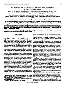
A. Current Users and Required Bandwidth The first BoD service demonstration was performed between Hokkaido Univ. and NII in February 2008 [4]. It involved transmitting a 1.5-Gbps non-compressed highdefinition video. SINET3 started to provide BoD services to real projects in June 2008. The first project is the e-VLBI project led by the National Astronomical Observatory of Japan (NAOJ). It uses radio telescopes located near Yamaguchi Univ., the National Institute for Fusion Science (NIFS), the High Energy Accelerator Research Organization (KEK), and Hokkaido Univ. (Fig. 10(a)), and the data measured at these sites are transferred to NAOJ via 2.4-Gbps ATM interfaces. SINET3 has a bandwidth granularity of VC-4 and accommodates various paths in arbitrary SDH time slots. Therefore, we decided to accommodate a 2.4-Gbps interface in VC-4-17v. We established seventeen independent VC-4 paths between the source and destination layer-1 switches because the ATM interfaces are accommodated in separate modules of the layer-1 switches. The project found the first fringe for the international celestial reference frame object “0400+258” on June 12, 2008. The second project is the high-quality remote backup project, which backs up huge amounts of data with a highperformance transfer protocol. The data backups are done between Osaka Univ., NII & NTT, Hokkaido Univ., and Kyushu Univ. (Fig. 10(b)). The project is currently evaluating the transfer performance between the sites by varying the path bandwidth from 150 Mbps (VC-4-1v) to 1.05 Gbps (VC-4-7v) over GE interfaces. The third project is a room-sharing video system, called tRoom, which allows people at different sites to feel as if they are in the same room by using multiple screens and cameras on the walls. Doshisha Univ. and NTT Communication Science
9 10 11 12 13 14
No. of transit switches
Path setup/release time
(a) e-VLBI project.
1
0
1 2
3
4
5
6
7
8
(1)
9 10 11 12 13 14
No. of transit switches
(a) e-VLBI project.
(b) High-quality remote backup project.
Figure 11. Path setup/release times for two projects.
Labs are evaluating the system performance between Atsugi and Kyoto. The system requires a high-quality communication environment with a maximum of a 300 Mbps bandwidth to transfer eight-sided high-definition video images, voices, and control signals. B. Times for Path Setup and Release Here, we will discuss the times for a path setup and release for e-VLBI and high-quality remote backup projects. As for the e-VLBI project, we show the times between NAOJ and three places, Yamaguchi Univ., NIFS, and KEK. The routes were calculated for the maximum available end-to-end bandwidth. For example, the route between Yamaguchi Univ. and NAOJ transited the edge L1SW at Yamaguchi Univ., the core L1SWs at Hiroshima, Kyoto, Osaka (L1SW-1 or L1SW-2&1), Nagoya (L1SW-1&2), and Tokyo1 (L1SW-1&2), and the edge L1SW at NAOJ: a maximum of ten L1SWs (Fig. 5). Figure 11(a) plots the average times for path setup/release versus the number of transit layer-1 switches. The setup/release time was defined as the difference between the time when the BoD server sends a “createSNC/deleteSNC REQ” and the time when it receives the “notification (create/delete CMPLD)”. To create/delete 17 VC-4 paths, we first created/deleted each VC4 path in series after receiving each “notification (create/delete CMPLD)”. However, we found that this operation takes a long time. Therefore, we refined the mechanism to create/delete paths in parallel right after receiving each “createSNC/deleteSNC RESP.” This dramatically shortened the times for setup and release. We understand that the times are
This full text paper was peer reviewed at the direction of IEEE Communications Society subject matter experts for publication in the IEEE ICC 2009 proceedings
Path setup/release time
[min] 14 13 12 11 10 9 8 7 6 5 4 3 2 1 0
2.4 Gbps (setup) 1.05 Gbps (setup) 2.4 Gbps (release) 1.05 Gbps (release)
presented the overall architecture necessary for providing BoD services, the path calculations under given conditions, and the interfaces between the user, BoD server, and layer-1 platform. We presented examples of the actual use of BoD services and evaluated the setup/release time. We will continue to search for new scientific research areas that effectively use the BoD capabilities. ACKNOWLEDGMENTS
Starting at 2.4 Gbps Starting at 1.05 Gbps
Figure 12. Path setup/release times for continuous operation.
still large, but because our layer-1 switches need enough time to cross-connect the TDM channels per VC-4, these times are within the expected range. The high-quality remote backup project needed to change the end-to-end bandwidth in order to evaluate the performance of the transfer protocol. We, therefore, evaluated the path setup and release times for the bandwidths of 150 Mbps, 600 Mbps, and 1.05 Gbps between Hokkaido Univ. and other places. The routes were calculated for the maximum available end-to-end bandwidth. For example, the route between Hokkaido Univ. and Kyushu Univ. transited the edge L1SW at Hokkaido Univ., the core L1SWs at Sapporo, Sendai, Tsukuba, Tokyo (L1SW2&1 or L1SW3&1), Nagoya (L1SW-2&1), Osaka (L1SW-1 or L1SW-1&2), Kyoto, Hiroshima, and Fukuoka, and the edge L1SW at Kyushu Univ. Figure 11(b) shows the setup and release times versus the number of transit layer-1 switches. Here, we gathered the bandwidth from the parallel links, and the numbers in parentheses in Fig. 11(b) indicate the number of divisions. We currently divided the bandwidth whenever the BoD server finds multiple links starting at the source layer-1 switch. Therefore, the figure has a maximum of seven divisions. The time elongates for a larger number of divisions. We evaluated the setup (release) times of the two paths when the BoD server received simultaneous requests to set them up (release them). The paths were a 2.4-Gbps path between Yamaguchi Univ. and NAOJ (path A) and a 1.05Gbps path between Hokkaido Univ. and Kyushu Univ. (path B) (Fig. 12). In the case of starting from the setup of path A, after receiving the “createSNC RESP” of the 17th VC-4 path belonging to path A, the BoD server starts to set up the first sub-path belonging to path B and has to wait for the “notification (create CMPLD)” message of the first sub-path before adding other sub-paths. In contrast, the BoD server can start to set up path A right after receiving the “createSNC RESP” of the first sub-path of path B. This shortened the total setup time by nearly two minutes. Therefore, we found that we can reduce the total setup time by taking into account the setup sequence of the layer-1 paths. We didn’t see a big difference between the two cases for the total release time. VI.
CONCLUSION
This paper described the detailed implementation and evaluation of the layer-1 BoD capabilities in SINET3. It
We wish to thank all the members of the Organization of Science Network Operations and Coordination for their support of SINET3. We are also grateful to Ms. Tamaki Saimei of NTT Communications, Mr. Eiji Kawa, Mr. Yuichiro Ohno, and Mr. Yuji Kamata of NTT Advanced Technologies, and Prof. Jun Adachi, Prof. Shoichiro Asano, Mr. Yoshiyasu Shizuta, Mr. Makoto Nakao, Mr. Shinji Takano, Mr. Tetsuro Shimoda, Mr. Jun-ichi Sayama, Mr. Ken-ichiro Minomo, and Mr. Akira Niitsuma of NII, for their continuous cooperation and support. REFERENCES [1] [2] [3]
[4]
[5] [6]
[7] [8] [9] [10] [11]
[12] [13]
[14]
[15]
[16]
R. Summerhill, “The new Internet2 network,” 6th GLIF meeting, Sep. 2006. M. Campanella, “Development in GEANT2: end-to-end services,” 6th GLIF meeting, Sep. 2006. S. Urushidani, J. Matsukata, K. Fukuda, S. Abe, Y. Ji, M. Koibuchi, S. Yamada, K. Shimizu, T. Takeda, I. Inoue, and K. Shiomoto, “Layer-1 bandwidth on demand services in SINET3,” Globecom 2007, Dec. 2007. S. Urushidani, K. Fukuda, Y. Ji, S. Abe, M. Koibuchi, M. Nakamura, S. Yamada, K. Shimizu, R. Hayashi, I. Inoue, and K. Shiomoto, “Resource allocation and provision for bandwidth/networks on demand in SINET3,” 2nd IEEE Bandwidth-on-Demand Workshop, Apr. 2008. N. Kawaguchi, “Optical fiber connected VLBI network in Japan,” 4th eVLBI workshop, Jul. 2005. K. Harada, T. Kawano, K. Zaima, S. Hatta, and S. Meno, “Uncompressed HDTV over IP transmission system using ultra-high-speed IP streaming technology,” NTT Technical Review, vol. 1, no. 1, pp. 84-89, Apr. 2003. ITU-T Recommendation G.7041, “Generic framing procedure (GFP),” Aug. 2005. ITU-T Recommendation G.707, “Network node interface for the synchronous digital hierarchy (SDH),” Dec. 2003. ITU-T Recommendation G.7042, “Link capacity adjustment scheme (LCAS) for virtual concatenated signals,” Mar. 2006. L. Berger, “GMPLS signaling resource reservation protocol: traffic engineering,” RFC3473, Jan. 2003. E. Mannie and D. Papadimitriou, “Generalized multi-protocol label switching (GMPLS) extensions for synchronous optical network (SONET) and synchronous digital hierarchy (SDH) control,” RFC4606, Aug. 2006. K. Kompella and Y. Rekhter, “OSPF extensions in support of generalized multi-protocol label switching (GMPLS),” RFC4203, Oct. 2005. J. Lang, B. Rajagopalan, and D. Papadimitriou, “Generalized multiprotocol label switching (GMPLS) recovery function specification,” RFC4426, Mar. 2006. G. Swallow, J. Drake, H. Ishimatsu, and Y. Rekhter, “Generalized multiprotocol label switching (GMPLS) user-network interface (UNI): resource reservation protocol - traffic engineering (RSVP-TE) support for the overlay model,” RFC4208, Oct. 2005. J. Edmonds and R. M. Karp, “Theoretical improvements in algorithmic efficiency for network flow problems,” Journal of the ACM, vol. 19, Issue 2, pp. 248-264, Apr. 1972. TM FORUM 814A version 2.1, “TM FORUM MTNM implementation statement template and guidelines: NML-EML interface for management of SONET/SDH/WDM/ATM transport networks,” Aug. 2002.