presents an evaluation of the network's performance under different loads and Section VI concludes. II. ON-CHIP NETWORKS. The move to on-chip networks ...
Appears in ICCD 2006. IEEE copyright restrictions apply.
Implementation and Evaluation of On-Chip Network Architectures Paul Gratz∗ , Changkyu Kim† , Robert McDonald† , Stephen W. Keckler† and Doug Burger† ∗
Department of Electrical and Computer Engineering, University of Texas at Austin † Department of Computer Sciences, University of Texas at Austin {pgratz, ckkim, robertmc, skeckler, dburger}@cs.utexas.edu
Abstract— Driven by the need for higher bandwidth and complexity reduction, off-chip interconnect has evolved from proprietary busses to networked architectures. A similar evolution is occurring in on-chip interconnect. This paper presents the design, implementation and evaluation of one such on-chip network, the TRIPS OCN. The OCN is a wormhole routed, 4x10, 2D mesh network with four virtual channels. It provides a high bandwidth, low latency interconnect between the TRIPS processors, L2 cache banks and I/O units. We discuss the tradeoffs made in the design of the OCN, in particular why area and complexity were traded off against latency. We then evaluate the OCN using synthetic as well as realistic loads. We found that synthetic benchmarks do not provide sufficient indication of the behavior of realistic loads on this network. Finally, we examine the effect of link bandwidth and router FIFO depth on overall performance.
I. I NTRODUCTION In the past, processor designers used proprietary busses to connect the processor to its memory and I/O devices. As clock frequencies and design complexity have increased, industry moved to standardized bus protocols, such as the Rambus protocol for SDRAM communication [1]. The next logical step is a commodity network architecture, as exemplified by the Hypertransport protocol [2] used to connect processor chips to I/O and network devices. A similar progression is ongoing in on-chip interconnect. Traditional microprocessor designs rely on ad-hoc unit-to-unit busses. More recently “System on a Chip” (SoC) systems have employed standardized busses such as the AMBA bus from ARM for on-chip interconnect [3]. On-chip networks represent the next logical step in on-chip interconnect. In this paper we discuss and evaluate the design and implementation of one such on-chip network, the TRIPS prototype processor’s on-chip network (OCN). Using the OCN as an example, we will show that on-chip networks provide important improvements over busses and have different design constraints than off-chip networks. We will also explore the latency and bandwidth of a typical load on the OCN and analyze its performance under load. The TRIPS OCN, shown on the left side of Figure 1, has characteristics that differentiate it from other networks, on and off-chip. It is a 4x10, 2D, wormhole routed mesh network with four virtual channels. It provides a peak injection bandwidth of 76 GB/sec at its architected frequency of 500 MHz. Low latency is a major design goal of the OCN because its main purpose is to interconnect L2 banks and the TRIPS processors.
Fig. 1.
TRIPS chip block diagram
Each router was only allowed to have one pipeline stage; area and router complexity were sacrificed to achieve low latency. Another key difference is its re-mappability. The OCN can have its system address to network address translation changed on the fly during normal operation. Further details are provided throughout the paper. Section II compares and contrasts on-chip and off-chip networks. Section III describes related work in on-chip interconnect. Section IV describes the design and implementation of the TRIPS OCN along with lessons learned. Section V presents an evaluation of the network’s performance under different loads and Section VI concludes. II. O N -C HIP N ETWORKS The move to on-chip networks has several motivations which are similar to those that drove off-chip networks. The design characteristics of on-chip networks however differ in multiple ways. A. Motivation The latency and electrical behavior of long wires scale poorly with diminished feature sizes due to a smaller crosssectional area. On-chip buss speeds are at a distinct scaling
disadvantage because they connect components spread across the chip. In addition, multi-drop busses require protocols to ensure exclusivity among the transmitters and suffer from poor electrical behavior as long wires on-chip begin to look more like transmission lines. On-chip networks enjoy a scaling advantage relative to busses since network wire lengths between adjacent routers can be kept short and uni-directional. On-chip networks also enable the pipelining of data and a much greater aggregate bandwidth than busses. Finally, design complexity can be reduced since the router only needs to be designed once and replicated for use wherever needed. B. Design Characteristics Bandwidth: The bandwidth of off-chip networks is typically much lower than on-chip networks. Off-chip networks are constrained in bit width by the expense of each chip pin. On-chip networks’ wires are constrained by the number of metal layers and pitch of on-chip wire routing, allowing onchip networks to have a much higher bandwidth than their off-chip counterparts. The greater bit-width allows the packet length of an on-chip network to be much shorter for the same amount of data, compared to an off-chip network. These differences affect the optimum choice of routing algorithm and network topology for on-chip networks. Latency: In off-chip networks, a router on one chip will be connected by board traces to a router on another chip. Differences in wire length and chip placements create significant clock and data skew between chips in the same network, therefore off-chip networks typically resynchronize data at each router. Synchronization adds two to three network cycles of latency per hop as a result. Off-chip networks run at a lower frequency than the rest of the chip, compounding the latency required for synchronization. Data must also be resynchronized upon arrival at the destination chip. By contrast, on-chip networks can be designed to have only one cycle per hop because synchronization is not needed. Single hop routing delays greatly decrease the end-to-end latency of the packets on the network relative to off-chip networks. Timing: Off-chip networks typically are clocked at much lower frequencies than the processor’s main clock because their timing is dominated by transmission line capacitances and the relative skews of off-chip interconnect. On the other hand, on-chip networks can be designed to be clocked by the main processor clock because the wire lengths are much shorter and the relative data skews are minimal. Keeping the frequency up places a strong constraint on how much logic may be placed on the router’s critical path prior to launching the flit to the next router. Area: Area is not a strong constraint for off-chip networks because there is typically only one off-chip router per chip. In on-chip networks, depending on the granularity of the network, the routers may take up a significant fraction of the total die area, constraining the area allowed for buffering and therefore affecting the number of virtual channels and the bit width of the network.
III. R ELATED W ORK While on-chip routed networks have been proposed and studied in the academic literature, to date there have been very few implementations of routed on-chip networks. Dally and Towles [4] proposed a 2D torus network as a replacement for global interconnect. They claim that on-chip network modularity would shorten the design time and reduce the wire routing complexity. Our experience bears this out. On-chip routed networks have also been proposed for use in SoCs such as in CLICHE [5], in which a 2D mesh network is proposed to interconnect a heterogeneous array of IP blocks. Our work implements something similar but in the context of a processor, as opposed to a SoC. The MIT RAW processor contains a 4x4 mesh network to interconnect its processor tiles which is principally designed for the transmission of scalar operands [6]. However, this network is also used to carry memory system traffic between the pins and the processors for cache refills. TRIPS also has an operand network (OPN) to transmit operands among the ALUs within the processor core. The TRIPS OCN described in this paper is optimized for memory traffic, rather than operand traffic. On-chip memory system traffic is often carried on a bus that connects the processor to a secondary cache, either on or offchip. The Alpha 21364 [7] has a bus connecting the processor to its L2 cache that is capable of one transaction per cycle and is 16 bytes wide in each direction. More recent designs, such as IBM’s Power4 [8], which contain multiple processors and multiple cache banks, use a crossbar network to connect processor cores on one side to L2 cache banks on the other side. The Power4’s interconnect is non-uniform with 32 bytes per cycle available per processor for reads but only 8 bytes per cycle available for writes. The crossbar network gives the Power4 cores the ability to share its three independent cache banks while doubling the network bandwidth of the Alpha 21364. The IBM Cell processor represents a significant step forward in the use of on-chip networks in processors. The cell processor is composed of nine processing elements interconnected with external I/O and DRAM Memory by the “Element Interconnect Bus” (EIB) composed of four concentric rings [9]. The EIB supports up to three simultaneous transfers per ring and each ring is 16 bytes wide. The TRIPS processor extends the concept of on-chip networking with its 10x4 routed mesh on-chip network. The OCN connects two processor cores, each with 5 memory access ports to a network of level-2 cache banks and I/O controllers. Table I compares the bandwidth of these approaches. TRIPS can achieve an injection bandwidth of 160 bytes per cycle, far exceeding that of bus-based approaches. In this context peak bandwidth means both processors are injecting on all network links simultaneously. While the TRIPS prototype is designed to only run at 500MHz, network based approaches with short point-to-point wires are inherently more scalable than multidrop busses. The mesh network also allows request queuing in
Chip Alpha 21364 Power 4 IBM Cell TRIPS
Processors 1 2 9 2
Ports 2 7 12 26
Interconnect Bus Crossbar Ring 2D Mesh
Injection Bytes/Cycle 16 64(16) reads(writes) 144 160
Inj Bandwidth 16 GB/sec 80(20) GB/sec 219 GB/sec 74 GB/sec
Bisection Bandwidth 16 GB/sec 80(20) GB/sec 195 GB/sec 64 GB/sec
Frequency 1GHz 1.3 GHz 1.6GHz 500MHz
TABLE I L2 MEMORY SYSTEM INTERCONNECT FOR SEVERAL PROCESSORS
Î ¤ìês m sì�
D1w·�m�ì*�
·�m�ì*�
D1w·�m�ì*�
súCì�]¤ ú¤��
�
·
[QI�|ì¤ú
QêIì �
Cú ¤
m �¼�
[QI�|ì¤ú
1
m �¼�
*I7ì�ú m
C
|*Iì
·Î�*I w¼ê]
D1w·�m�ì*�
1�úIImê� E
D1w·�m�ì*�
1ú]�¤
D1w·�m�ì*�
Fig. 3.
IV. OCN D ESIGN AND I MPLEMENTATION The OCN in the TRIPS processor serves as a network to interconnect the two TRIPS processor cores, the individual banks that form the second level cache and the I/O units. The OCN must be able to provide sufficient bandwidth at low latency to avoid being a performance bottleneck for the processor cores. The OCN also provides a means to reconfigure the on-chip memory and map memory banks in and out of the level-2 cache. For the OCN, this implies a mechanism to convert a system memory address to a network memory bank address which can be changed by altering the contents of a memory mapped network address table. A. Design Figure 1 shows a high-level block diagram of the TRIPS prototype chip with two processors on the right side and the second level cache with IO units interconnected by the OCN on the left hand side. The OCN consists of 16 Memory tiles (M-Tiles), each containing an OCN router and a level-2 cache bank. 24 Network tiles (N-Tiles) containing an OCN router and the system address translation tables are surrounded by the 2x8 array of M-Tiles. These together form a 4x10, 2D mesh. Connected to the OCN along the top and the bottom are the I/O tiles, including two DMA controllers, two SDRAM controllers (SDCs), the external bus controller (EBC) and the chip-tochip network controller (C2C). The I and D tiles make up the TRIPS processor L1 instruction and data caches respectively.
úCìl
QêIì
·ÎÎ�*IIw ¼�ê]I7êì�ú]w ¼êm7*
ú�ê7
1ú]�¤ Ò]ì*�ê�*
Memory tile block diagram highlighting OCN router in detail.
the network FIFOs for a graceful degradation of service when the request load is high. This comes at the price of area; the TRIPS OCN network routers take approximately 11% of the whole TRIPS chip die area.
ú�ìl
|*Iì
D1w·�m�ì*�
ú�ê7 l
·
Fig. 2.
úCìl
¤Ò
l¼ ¤
�
Cú ¤
�
|¼ E �
Q
�
[QI�|ì¤ú
�
l¼ ¤
[QI�|ì¤ú
�
¤Ò
�
�
·
�
ú�ìl
�
1 ¤Ò
�|ì¤ú �
1 ¤Ò
¤ú �
DQ1IÎ
[QI�|ì¤ú
Network tile block diagram in detail
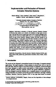
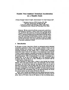
Further details on the TRIPS processor architecture may be found in Burger et. al. [10]. The OCN network is Y-X dimension-order, worm hole routed; flow control is credit-based, meaning that each node keeps track of the number of empty buffers in all of its neighbors’ input FIFOs to determine when it is safe to send more data. Packets travel on one of four virtual channels, designated “Primary Request” (Q1), “Secondary Request” (Q2), “Secondary Reply” (P2), and “Primary Reply” (P1) in order of increasing priority. The packets range in size from 16 bytes to 80 bytes long broken up into between one and five, 16 byte flits. OCN clients connect directly to N-Tiles and include 10 ports for instruction and data traffic to/from the two on-chip processors, two on-chip DMA controllers, two on-chip SDRAM controllers, one slow external bus controller, and one highspeed chip-to-chip (C2C) controller. The C2C port is a direct extension of the OCN (albeit at one-eighth the bandwidth per channel), and enables TRIPS chips to be connected gluelessly to one another in a larger system. The OCN can be scaled by either increasing the mesh dimensions (more M and N tiles) or by utilizing the spare client connections on the east side. OCN Router: Figure 2 shows an M-Tile along with its embedded OCN router. The OCN router is typical of virtual channel router designs. Incoming packets are latched into one of the input FIFOs in one of five input directions, North, South, East, West or Local for the L2 bank itself. There is enough incoming packet storage available for two flits of data per direction, per virtual channel. A 4x4 crossbar network connects each input to every other possible output; a 5x5
crossbar is unnecessary since a packet coming in from one direction (i.e. north) cannot depart in that same direction. In cases of contention the crossbar selects the higher priority channel. The router uses a round-robin arbitration scheme to resolve contention among requests at the same priority level. The direction of the last packet sent in each direction is stored and used on the next arbitration cycle to ensure routing fairness and livelock avoidance. A credit-based flow control scheme tracks the number of available buffers in neighboring receiver FIFOs. When a receiver removes a flit from an incoming FIFO, the receiver sends a credit signal back to the sender to signify more FIFO buffer space is available for future flits. Network Address Translation: Figure 3 contains a detailed block diagram of the Network tile. The N-Tile forms a gateway to the OCN for clients, such as the TRIPS processors and IO units, to inject packets. The N-Tile contains an OCN router similar to that discussed in the previous section. The main difference is that the local interface is connected to an OCN client instead of an L2 cache bank. Virtual-to-system address translation is performed within processors using standard TLBs, but TRIPS supports an additional level of translation to enable reconfiguration of the memory system. An N-Tile translates the system physical address to a network address using a simple table when the OCN client transmits a packet header to an N-Tile. This table consists of 16 entries of 8 bits each and is indexed using 4 bits from the system physical address. Each table entry contains the X-Y coordinates of the M-Tile to which the address region is mapped. The table itself is memory mapped and can be modified on-the-fly by the runtime system. Further details on valid address mappings are described below. B. Capabilities and Characteristics Bandwidth and Latency: The OCN provides sufficient bandwidth to service both processor cores’ first level cache fills and spills. In a given cycle, each processor core can initiate a peak of five L1 cache fill or spill requests. The OCN has 128-bit (16-byte) wide links between routers. Its peak injection bandwidth is 74 GB/sec at its architected frequency of 500MHz when both processors inject packets on all links simultaneously. Measuring bandwidth differently, the OCN has a bisectional bandwidth of 64 GB/sec from north to south and from south to north across the middle of the network. The OCN also ensures a low latency on requests. The L1 data cache is 32KB and its hit latencies are on the order of 5-12 cycles. The L2 cache is organized as a static NUCA style cache [11]. Because OCN incurs one cycle per hop of latency, in the best case the OCN can provide a 3 cycle latency each way for requests to the nearest L2 cache bank not counting the L2 access time itself. In the worst case there could be 13 cycles of latency each way to go from the top or bottom processor connection to the furthest Memory tile. Adding in the actual L2 bank access time the L2 hit latencies range from 7 to 27 cycles assuming no contention in the network or for the bank.
Component Router input FIFOs Router crossbar Router arbiter logic Total for single router
% Router Area 75% 21% 4% 100%
% M-Tile Area 10.2% 2.9% 0.6% 13.8%
TABLE II A REA USED BY VARIOUS COMPONENTS OF THE OCN ROUTERS
Component Latency Control Path Virtual channel arbitration 600ps Direction arbitration 640ps Input FIFO Control 590ps Latch setup + clock skew 370ps Total 2.2ns Data Path Out of FIFO through VC Mux 430ps Through output mux 180ps Latch into input FIFO 120ps Latch setup + clock skew 370ps Total 1.1ns
% Path 27% 29% 27% 17% – 38% 16% 11% 33% –
TABLE III T IMING FOR CONTROL AND DATA PATH IN THE OCN ROUTERS
Area and Timing: The TRIPS processor is manufactured using a 130nm IBM ASIC technology. Table II shows the breakdown of the area consumed by the components of the OCN router as well as the total overhead of the all OCN routers and N-Tiles. The router input FIFOs dominate the router with 75% of the router area. The crossbar interconnect comes next with 21% of the router area. The router arbitration and routing logic only consumes 4% of the total area of the router. A single OCN router takes up approximately 14% of the M-Tile. All of the OCN routers and N-Tiles put together consume 32.5% and 10.9% of the area of the OCN and TRIPS chip respectively. The area consumption of the routers was higher than initially projected largely due to design tradeoffs discussed in section IV-C. Synopsys Primetime was used to evaluate the critical paths for the TRIPS chip. Table III shows a component based breakdown of the critical path for the data and control paths of an OCN router or N-Tile. In this table the component latencies were generated with Synopsys Primetime using the “worstcase” corner of the 130nm IBM ASIC standard libraries and have been scaled by 2/3 to estimate nominal timing. Of note is that the control path is much more constrained than the data path in these routers. Also note that there is very little cycle time left over for wire delay. In 130nm, wire delay is not as much of a design constraint as it will be in future technologies. Flexibility: The OCN provides a mechanism for remapping system memory addresses to different OCN network nodes. Any system address normally cached by the L2 banks may be mapped to any M-Tile or directly routed to the SDRAM controller, allowing the OCN to have a mode where some
M-Tiles are in scratch pad/direct addressed mode. The L2 requests that are displaced are redirected towards other tiles that are still operating in L2 mode or directly to the SDRAM controllers. Alternatively, all the tiles may be mapped in scratch pad mode and all L2 traffic can then be forwarded to the SDRAM controllers directly. These different mappings are effected by modifying the N-Tiles’ address translation tables. These tables control the mapping between address region and physical M-Tile. The N-Tiles also control the interleaving of addresses across the M-Tiles. In shared cache mode, addresses are interleaved (on cache line boundaries) across all the M-Tiles evenly to provide the full set of 16 64KB cache banks for the use of both on-chip processors. The N-Tiles have a second mode, called the private cache mode, in which the full address space of a given TRIPS chip is split on 2GB boundaries. The L2 cache banks are also split in half, the top eight banks cache the first 2GB block, the bottom eight banks cache the second 2GB block. This allows the each processor to use a private subset of the L2 independently without interfering with the other assuming the OS page mapping is setup appropriately. Chip-to-Chip Communication: A key design requirement of the TRIPS processor system is the ability to link several TRIPS processor chips into a larger system. The chip-to-chip (C2C) network was designed to fulfill this requirement. The C2C is a simple extension of the OCN protocol to off-chip connections, consisting of a 32 bit wide, 2D mesh network with two virtual channels and credit based flow control. Its clock frequency may be set at 1/2 to 1/4 the system clock of the OCN. C2C packets are simply OCN packets broken up into 32 bit chunks. The first 32 bits of the OCN packet contains routing information for the C2C network and serves as the C2C packet header. The design of the memory system ensures that only two of the OCN virtual channels will be used on the C2C so only those two channels are provisioned. Two stages of synchronization are used between the OCN and C2C as well as between each C2C router to allow each C2C to operate asynchronously from the OCN and from other C2Cs. A total of three cycles of latency for each C2C router is required for synchronization and pipelining. C. Design Tradeoffs Virtual Channels: We realized early on that dependency between replies and requests could cause a protocol deadlock with dimension order routing. This problem was exacerbated by the potential fill or spill requests that would also be dependent on the final reply. While one could solve the problem with an adaptive routing algorithm and deadlock breaking, the TRIPS processor clock frequency did not allow enough cycle time for much work in a single cycle. Instead of slowing the clock frequency, pipelining the design would allow for adaptive routing and deadlock breaking. A deeper pipeline would have increased the number of cycles per hop in each router, multiplying the round trip cycles for L2 accesses. Alternate to deadlock breaking, we chose to implement enough virtual channels to ensure deadlock avoidance. The
Fig. 4. Accepted traffic verses offered traffic as a percentage of maximum input bandwidth for bit-complement and random traffic
total of four virtual channels quadrupled the amount of FIFO buffering needed. This was a direct tradeoff of area for cycle time and low request latency. Credit Based Flow Control: We choose to implement the credit based flow control for the OCN (as opposed to on/off flow control) because the credit based algorithm takes the flow control off the packet transmission critical path. It allows pipelining of the flow control because the sender does not have to react to the returned credit until the following cycle. In order to avoid flit pipeline bubbles with the one cycle lag in returned credits however, we needed at least two flits of buffering in the receiver. This was another case of trading off area for cycle time. V. E XPERIMENTS In this section, we evaluate the OCN network experimentally to gain an understanding of its performance under different types of traffic. We first examine the OCN using standard network characterization techniques. We then evaluate the network’s performance with expected traffic derived from benchmarks. Finally we examine the effect on network performance of changing the baseline link bandwidth and router FIFO capacity. A cycle-accurate network simulator was used for all network latency and bandwidth measurements. For SPEC CPU2000, we used a cycle-accurate TRIPS processor simulator to generate OCN request traces, which we then ran through the network simulator. In all cases the effect of having both processors running was emulated to approximate traffic loads found in CMP operation without memory sharing. A. Synthetic Statistical Loads Mesh networks are typically evaluated by examining their performance on statistically random generated loads. One common load is “bit complement” traffic in which each node exchanges packets with a node on the opposite side of the network at a uniform random distributed offered rate. Figure 4 shows the offered vs. accepted bandwidth. In the figure the accepted bandwidth tracks the offered bandwidth for bitcomplement traffic perfectly up to 20%, at which point the accepted bandwidth degrades slightly and levels off at just
Fig. 5. Latency in cycles verses offered traffic as a percentage of maximum input bandwidth for bit-complement and random traffic
under 20%. Figure 5 shows the average packet latency in cycles for increasing offered bandwidth rates. In the figure the average latency gradually increases from 9 to 15 cycles for offered rates of 1% to 16%. The latency then increases exponentially as the network becomes saturated. Bit-complement traffic does not closely match the actual traffic of the OCN because not all nodes are equal senders or receivers of traffic. One approach to get more accurate bandwidth and latency measurements than the bit-complement traffic is more realistic modeling of the traffic on the OCN. The “random” traffic model attempts to realistically model network traffic by randomly generating request–reply pairs between the processor links and the MT’s. In figure 4 the accepted bandwidth tracks the offered bandwidth up to approximately 32%. In Figure 5 the average latency in cycles for random traffic increases from 6 to 12 cycles for offered rates from 1% to 24% before increasing dramatically. The latency for random traffic follows a similar curve as the bit-complement traffic although it has a lower starting point of approximately 6.5 cycles. The curves shown in Figure 4 and Figure 5 are fairly typical for a 2D mesh network of this shape.
Fig. 6. Histogram of the percentage of the sixtrack and twolf benchmarks with various offered rates
B. Benchmark-Generated Traffic One known issue with uniformly distributed injection time, synthetic traffic is that it does not accurately model the nonuniform injection times found in real traffic. Non-uniform or “bursty” traffic can have a strong effect on the actual average packet latencies relative to idealized uniform traffic loads due to the non-linear response of latency to offered rate when the network becomes congested. To evaluate the effect of realistic loads we generated memory system traces from a cycleaccurate TRIPS processor simulator for the Minne-SPEC [12] suite of reduced input set SPEC CPU2000 benchmarks. These traces were then analyzed to determine their “burstiness”. We propose histograms of the percentage of all packets injected with given instantaneous offered rates as a metric of the burstiness of a network trace. The principle of this measure is traces that are more bursty should have a wider set of offered rates than non-bursty. We generated these histograms for each trace to measure their burstiness. Figure 6 shows
Fig. 7. Offered rate and average latency for a sample from the middle of sixtrack
this histogram for the sixtrack and twolf benchmarks. The histogram shows sixtrack to have wide array of offered rates have significant quantities of requests, from near 0% to 20% of max bandwidth. By contrast twolf shows almost all requests have an offered rate of between 2% and 7%. These results imply that sixtrack is burstier than twolf. These traces were also run through the OCN simulator to determine the instantaneous offered rate and latency. Figure 7 shows these statistics for a small, million-cycle sample, taken from the middle of sixtrack. In the offered rate portion of the figure there are three regions, that may be associated with
7*��I
7�
]�
]*��I
]�
ê*��I
ê�
¼*��I
¼�
5CC|¤|DL?c
�
ê m1¤�
ê� ¼� w� I�
�
�
�
�
�
�
�
�
�7C* �
¼¬5÷L
¼� w� I� *�
�
�
�
Dm�D� C
;[1Cs
;�1
D�ì
D[úl
�s17 |
÷C*?ì71|
�71 C1
ì1�E
ìC 7
ì l
��
7�
17l
CQm7|C
¤Ò��I
71
�
�
�
�
�
[ ú[1�Q
.;¤QD
.ú
¤[;m
�[1�
�1D¤ìl
úì�Q
�E1s
I¬5÷L
ê�
7��úm
FIFO buffer depth: While Section IV-C discussed the tradeoffs among area, cycle time and latency, this section
*¬5÷L ]�
7� �
C. Parameter Exploration
�Q�ì
Q?l��ì
Fig. 9. Latency of packets for various SPEC CPU2000 benchmarks with different router FIFO buffer depths
7ìì�
sixtrack program phases. The first region has a relatively low average offered rate of 2.5% and starts at the beginning of the sample. This region corresponds to a very high average latency of around 100 cycles. The second region starts around cycle 250000 and extends to approximately cycle 400000. This region has an average offered rate of 5.25% and an associated average latency of 40 cycles. The final region starts at approximately 400000 and continues throughout the rest of the trace. The region has an average offered rate of 1% and average latency of 15 cycles with some exceptions. The first region only has a 2.5% offered rate however the latency is extremely high. Further investigation into that region showed that although the offered rate is relatively low, a large majority of the accesses are reads all destined to a small number of L2 banks causing heavy congestion in portions of the network. In the second region, the latency is much higher than the third despite an offered rate that is only 4% higher. Figure 8 shows the average offered rate and latency of each of the 20 SPEC CPU2000 benchmarks we can currently run on our system. For many benchmarks there does not appear to be a strong correlation between offered bandwidth and average latency, an observation that differs from the results from bit-complement and random traffic shown in dashed lines superimposed on the histograms. The benchmark sixtrack in particular has the highest average latency, nearly double the next highest latency, while it has only the fourth-highest offered rate. The benchmarks having offered rates greater than 1% all have an average latency higher than the offered bandwidth would imply. One exception is twolf, which has a slightly higher latency than bit-complement traffic would for the amount of offered traffic that it provides. These results, compared with those from Figure 6, imply that the OCN’s latency is generally higher under benchmark loads than under statistical loads and it is likely that the burstiness of the load is a measure of the degree to which the latency is higher.
�l
Fig. 8. Average offered rate and latency of packets for various SPEC CPU2000 benchmarks
E 1ú
Eìú
Q| ìQ
lì ¤C
Ò 1úI
ì¤
ìú�1
�
á��D.úL Ò¤�CC L �÷|¤�s|L �Ò|� Q
ìúúm
�
ì��ú
;�m;1|
÷.¤Ò|[
÷m¤
Ò;. C
1[Ҥ� E
1;ú
?|�¬ú�¤E1
m�¤1|¤
ús¤D
ú|1�
ú C
slm
|��E|
s�m
lm¼
¤�CÒQ
�¤Ò
�m1
�úúm
�mm �
�*��I
�
�
�
w*��I
I m1¤�
*�
�
?Ò¶Í.úm Ò¤�CC L w� �÷|¤�s|L �Ò|� QL
¬.QìEQ5Lì¤Q?lC
7�
¨÷|¤�s|L¿�Ò|�Q
ì�
�
* m1¤
�
¿�Ò|� Q �
5CC|¤|DL?cLI
ì*��I
Fig. 10. Latency of packets for various SPEC CPU2000 benchmarks with different OCN bit widths
evaluates the effect of these parameters on the performance of the network. Figure 9 shows the average latency for packets from the SPEC CPU2000 benchmark suite when the OCN routers’ FIFO depth is set at 1, 2 (the baseline), and 5 flits. The figure shows that decreasing the FIFO depth from 2 to 1 adds an average of 42% to the latency across all benchmarks. Going from 2 flits to 5 flits per FIFO however only reduces the latency by 2.1% on average. These results confirm our expectation, as only one flit available per channel cannot provide enough buffer depth to hide the credit pipelining latency. With more than 2 flits the extra buffering does not appear to make a significant difference in the network’s performance. We expect that more than 2 flits of buffering would only have an effect on a wormhole routed network when that network is congested with packets that are larger than 2 flits. One possible reason that we do not see much improvement with greater than 2 flits of buffering is that the congested portions of the benchmarks are dominated by traffic that is averaging around 2 flits in length. Channel width: Figure 10 shows the effect of doubling and quadrupling the OCN bandwidth by increasing the network’s channel bit width. The effect of increasing the network band-
width is minimal. Doubling the bandwidth only yields 7.1% average improvement and quadrupling it yields a 9.1% average improvement. The small effect’s likely cause is that as the bandwidth increases the proportion of overhead to payload goes down. Even at 4X the bandwidth there must be at least three total flits for the largest request reply pairs (one flit for request and two for reply in a read for example), as opposed to the 6 flits for a request and reply at the normal bandwidth. Smaller packets see even less improvement. The results of these parameter studies indicate that the channel width and FIFO depth in the OCN are appropriate for SPEC CPU2000like workloads. VI. C ONCLUSIONS AND F UTURE W ORK In this paper, we presented the design, implementation, and evaluation of the TRIPS on-chip network, a chip-level communication fabric that links the processor to the secondary cache banks and to I/O controllers. The OCN represents a step toward the replacement of on-chip busses by on-chip networks that can provide better bandwidth and scalability. Our design experience illustrated several tradeoffs including increased virtual channels rather than adaptive routing to increase routing speed at a cost of larger router area. Similarly, the credit based flow control traded off a higher area usage for improved cycle time. The cost in area for integrated networks such as the OCN is significant; 11% of the total area of the TRIPS chip is devoted to the OCN routers and Network tiles. The OCN was designed to provide single cycle per hop router latency for the second level cache while operating at the system clock frequency. The OCN achieved a single cycle hop latency by trading off the complexity of the router for cycle time. Our evaluation showed that on-chip networks should not be examined using only simple statistical workloads because real workloads tend to be bursty and not evenly distributed in destination, altering the desired network operating parameters. In particular we examined traffic generated by several of the SPEC CPU2000 benchmarks. We found that in benchmark generated traffic not all benchmarks showed the expected correlation between offered rate and latency shown in the synthetic workloads. Modifications of network design parameters were also explored. We found that, for the workload examined, the default FIFO depth of 2 was optimal and that increasing the bandwidth did not have a significant effect on the network performance. In our future work we intend to evaluate further the behavior of the network under different traffic loads and to examine means of reducing network area overheads without sacrificing latency or bandwidth. ACKNOWLEDGMENTS We thank the anonymous reviewers for their suggestions that helped improve the quality of this paper. This research is supported by the Defense Advanced Research Projects Agency under contracts F33615-01-C-4106 and NBCH30390004 and an NSF instrumentation grant EIA-0303609.
R EFERENCES [1] R. Crisp, “Direct Rambus Technology: The New Main Memory Standard.” IEEE Micro, vol. 17, no. 6, pp. 18–28, 1997. [2] C. N. Keltcher, K. J. McGrath, A. Ahmed, and P. Conway, “The AMD Opteron Processor for Multiprocessor Servers,” IEEE Micro, vol. 23, no. 2, pp. 66–76, 2003. [3] D. Flynn, “AMBA: Enabling Reusable On-Chip Designs,” IEEE Micro, vol. 17, no. 4, pp. 20–27, 1997. [4] W. J. Dally and B. Towles, “Route Packets, Not Wires: On-Chip Interconnection Networks,” in DAC, 2001, pp. 684–689. ¨ [5] S. Kumar, A. Jantsch, M. Millberg, J. Oberg, J.-P. Soininen, M. Forsell, K. Tiensyrj¨a, and A. Hemani, “A Network on Chip Architecture and Design Methodology.” in ISVLSI, 2002, pp. 117–124. [6] M. B. Taylor, W. Lee, S. P. Amarasinghe, and A. Agarwal, “Scalar Operand Networks: On-Chip Interconnect for ILP in Partitioned Architecture,” in HPCA, 2003, pp. 341–353. [7] S. S. Mukherjee, F. Silla, P. J. Bannon, J. S. Emer, S. Lang, and D. Webb, “A Comparative Study of Arbitration Algorithms for the Alpha 21364 Pipelined Router.” in ASPLOS, 2002, pp. 223–234. [8] J. M. Tendler, J. S. Dodson, J. S. F. Jr., H. Le, and B. Sinharoy, “POWER4 System Microarchitecture.” IBM Journal of Research and Development, vol. 46, no. 1, pp. 5–26, 2002. [9] D. Pham, T. Aipperspach, D. Boerstler, M. Bolliger, R. Chaudhry, D. Cox, P. Harvey, P. Harvey, H. Hofstee, C. Johns, J. Kahle, A. Kameyama, J. Keaty, Y. Masubuchi, M. Pham, J. Pille, S. Posluszny, M. Riley, D. Stasiak, M. Suzuoki, O. Takahashi, J. Warnock, S. Weitzel, D. Wendel, and K. Yazawa, “Overview of the architecture, circuit design, and physical implementation of a first-generation cell processor,” IEEE Journal of Solid-State Circuits, vol. 41, no. 1, pp. 179–196, January 2006. [10] D. Burger, S. W. Keckler, K. S. McKinley, M. Dahlin, L. K. John, C. Lin, C. R. Moore, J. Burrill, R. G. McDonald, W. Yoder, and the TRIPS Team, “Scaling to the end of silicon with EDGE architectures,” IEEE Computer, vol. 37, no. 7, July 2004. [11] C. Kim, D. Burger, and S. W. Keckler, “An adaptive, non-uniform cache structure for wire-delay dominated on-chip caches,” in ASPLOS, 2002, pp. 211–222. [12] A. J. KleinOsowski and D. J. Lilja, “MinneSPEC: A New SPEC Benchmark Workload for Simulation-Based Computer Architecture Research.” Computer Architecture Letters, vol. 1, 2002.