used to implement a two-dimensional 33 grid scroll chaotic attractor. The implementation of complex dynamics with low cost circuits is very appealing; moreover, ...
CHAOS 16, 013121 共2006兲
Implementation and synchronization of 3 Ã 3 grid scroll chaotic circuits with analog programmable devices Marian Hulub Faculty of Electronics and Telecommunications, Technical University “Gh. Asachi,” Bd. Carol I nr. 11, 700506 Iasi, Romania
Mattia Frasca, Luigi Fortuna, and Paolo Arena Dipartimento di Ingegneria Elettrica Elettronica e dei Sistemi, Università degli Studi di Catania, Viale Andrea Doria 6, 95125 Catania, Italy
共Received 11 November 2005; accepted 14 December 2005; published online 8 March 2006兲 The implementation of circuits with complex dynamics is a very challenging problem. In this paper we present a new chaotic circuit based on the dynamical equations introduced in IEEE Trans. Circuits Syst., I: Fundam. Theory Appl. 51, 2476–2490 共2004兲. This circuit has been realized by using programmable analog devices, and, in particular, field programmable analog arrays have been used to implement a two-dimensional 3 ⫻ 3 grid scroll chaotic attractor. The implementation of complex dynamics with low cost circuits is very appealing; moreover, the implementation of the chaotic attractor discussed in this paper is not present in the literature. The experimental results including the synchronization between two chaotic circuits show complete agreement with the simulation results reported in IEEE Trans. Circuits Syst., I: Fundam. Theory Appl. 51, 2476–2490 共2004兲. © 2006 American Institute of Physics. 关DOI: 10.1063/1.2164811兴 Recently, a new type of device called FPAA (field programmable analog array) has emerged. These devices are analog programmable circuits that allow the user to program them and thus to implement custom analog circuits. For this reason FPAA provides a useful tool for fast prototyping. On the other hand, chaotic circuits have an important role in the experimental study of chaos. Many chaotic circuits are indeed derived from well-known mathematical models based on nonlinear differential equations and permit their experimental characterization. In this paper we apply the approach based on FPAA to implement a new chaotic system in order to build up a new analog circuit with chaotic dynamics. I. INTRODUCTION
Analog computation is a fascinating paradigm in complexity studies and bioinspired electronic applications. However, the main drawback of analog computers is the difficulty of programming them. In the last decade a new type of device has emerged, called FPAA 共field programmable analog array兲, providing analog computation based on the switched-capacitor technique. Even though these devices include a small number of programmable blocks, called CAB 共configurable analog block兲, with few configurable modules 共CAMs兲 per CAB, they are ideal for rapid and reprogrammable analog design. This type of circuits has been chosen to implement a twodimensional 3 ⫻ 3 grid scroll chaotic attractor, designed based on the saturated function series method presented in Ref. 1. Multiscroll chaotic attractors have been extensively studied and it is no longer a difficult task obtaining them. Starting with Chua’s circuit,2 implementations based on it or 1054-1500/2006/16共1兲/013121/5/$23.00
other different approaches have been reported. N scrolls have been realized by using simple circuits in Refs. 3 and 4, CNNs in Refs. 5–7, or sine-function-based circuits in Ref. 8. Also, two-dimensional 共2-D兲 or three-dimensional 共3-D兲 multiscroll chaotic attractors have been obtained in Ref. 9 or Ref. 10. Stair circuit, hysteresis circuit, and saturated circuit are the three kinds of basic circuits used for creating multiscroll chaotic attractors. Saturated function series are used in this work for implementing the grid scroll. In fact, this approach has several advantages: a desired number of scrolls and their spatial positions and orientations can be arbitrarily selected by using the methodology developed in Ref. 1; moreover, saturation-based nonlinearities can be very efficiently implemented in electronic circuits. Beyond the well-known applications of chaos 共for instance, secure communications11 and chaos-based sensors12兲, the particular attractor chosen in this work can be applied in other recently developed chaos-based devices. In particular, it has been recently used to build up the navigation control system of a roving robot.13 The underlying idea of the navigation system, based on neurophysiological studies on perception, is to represent perception by chaotic attractors whose dynamical evolution depends on sensorial stimuli. To this aim, two-dimensional m ⫻ n grid scroll chaotic attractors are used because of their rich dynamics characterized by several scrolls, which may be the representation of perception under different sensorial stimuli. The paper is organized as follows: in Sec. II the design of the circuit is presented, the issue of the synchronization of two circuits is discussed in Sec. III, and in Sec. IV we conclude this paper with a brief conclusion.
16, 013121-1
© 2006 American Institute of Physics
Downloaded 15 Mar 2010 to 134.58.253.55. Redistribution subject to AIP license or copyright; see http://chaos.aip.org/chaos/copyright.jsp
013121-2
Chaos 16, 013121 共2006兲
Hulub et al.
II. CIRCUIT IMPLEMENTATION AND EXPERIMENTAL RESULTS A. The 3 Ã 3 grid scroll equations
The starting point of our circuit is the third-order n ⫻ m grid scroll chaotic attractor described by the following equations:1 x˙ = y −
d2 f共y;k2,h2,p2,q2兲, b 共1兲
y˙ = z, z˙ = − ax − by − cz + d1 f共x;k1,h1,p1,q1兲 + d2 f共y;k2,h2,p2,q2兲, with
f共x;k,h,p,q兲 =
冦
k共2q + 1兲,
if x ⬎ qh + 1,
k共x − ih兲 + 2ik, if 兩x − ih兩 艋 1,
− p 艋 i 艋 q,
k共2i + 1兲,
if ih + 1 ⬍ x ⬍ 共i + 1兲h − 1, − p 艋 i 艋 q − 1,
− k共2p + 1兲,
if x ⬍ − ph − 1,
where k is the slope of the saturated slope, h is the distance between two consecutive saturated slopes, p, q are integer constants controlling the number of scrolls in negative and positive directions of the variable. To obtain a 3 ⫻ 3 grid scroll chaotic attractor the following values for a, b, c constants and k, h, p, q were adopted: a = b = c = 0.7; d1 = d2 = 0.7; k1 = k2 = 10; h1 = h2 = 20; p1 = p2 = 0; q1 = q2 = 1. Since the dynamic range of the system variables 共x and y variables have peak-to-peak oscillations equal to 40 units, while the z variable to 10 units兲 is larger than that allowed by the FPAA device, a rescaling was necessary in order to accommodate with the permitted swing voltage. The following rescaling factors were chosen:
X=
x ; kx
Y=
y ; ky
Z=
z ; kz
kx = ky = 10;
kz = 5.
By applying this rescaling the system described by Eqs. 共1兲 becomes X˙ = Y − 5f共Y ;k2,h2,p2,q2兲,
Y˙ = 0.5Z,
共3兲
Z˙ = − X − Y − 0.5Z + 5f共X;k1,h1,p1,q1兲 + 5f共Y ;k2,h2,p2,q2兲, where
f共X;k1,h1,p1,q1兲 =
冦
− 0.1,
if X ⬍ − 0.1,
X,
if 兩X兩 艋 0.1,
X − 0.8, if 0.9 艋 X 艋 1.1, 0.3,
if X ⬎ 1.1.
冧
共4兲
冧
共2兲
B. Circuit implementation and experimental results
The FPAA used is the AN221E04, mounted on the Development Board AN221K04.14 These FPAA devices are composed of four programmable blocks, called CAB, each of them containing two configurable modules 共CAMs兲. The software used for programming them, AnadigmDesigner 2, has a friendly Graphical User Interface, well documented, where the user can place the desired CAMs into a preprocessed area called chip, representing the used FPAA, then wire them together and download the configuration directly to the FPAA through a serial port of the computer. CAMs may contain multiple circuit parameters and architectures that can be selected though CAM configuration. However, the user is not required to know the underlying fundamental circuits that are incorporated into the CAMs because they have been abstracted to a functional level at the user interface. It should be noticed that all blocks have switching characteristics, due to the switching capacitor technique used by FPAAs, and all signals are differential 共inputs and outputs, as well as interconnecting wires inside FPAAs兲. Due to this switched-capacitor technique many parameters of a CAM depend on the frequency of the clock driving the switched capacitors, the user having to its disposition an interval of values, which is function of the selected clock frequency. The adopted schematic for implementing system 共4兲 is presented in Fig. 1. Two FPAAs have been used to implement system 共4兲, both are represented in the schematic of Fig. 1. The three integrators, indicated as I2, I3, and SI2 from FPAA2 are the main blocks of our system. The integration constant for the integrators is 0.001 V / s. The sum block SD4 sums the two terms needed for the x variable: y and f共y ; k2 , h2 , p2 , q2兲. The gains for these inputs are unitary. The second input is an inverting input and its output is an input for the integrator I2, where the x variable is obtained. GH1 multiplies z variable by a factor equal to 0.5 and its output is
Downloaded 15 Mar 2010 to 134.58.253.55. Redistribution subject to AIP license or copyright; see http://chaos.aip.org/chaos/copyright.jsp
013121-3
FPAA 3 ⫻ 3 Grid scroll chaotic circuits
Chaos 16, 013121 共2006兲
FIG. 1. The adopted FPAA schematic for the implementation of the 3 ⫻ 3 scroll chaotic circuit.
an input for the integrator I3, where the y variable is obtained. The blocks SD1 and SD5 are summing the five terms needed for the z variable: in SD5 the x, y, and z terms are summed 共they have all negative gains兲, and in SD1 the f共x ; k1 , h1 , p1 , q1兲 and f共y ; k2 , h2 , p2 , q2兲 terms are summed. According to Eqs. 共3兲 all the inputs of these two CAMs have unitary gains, except for the third input of SD5 共which corresponds to the z variable兲, where the gain is 0.5. Their outputs are summed in the SumIntegrator SI2. There are two user-defined transfer functions, indicated as TF5 and TF4 in the schematic, which are implementing the two nonlinear functions, f共x ; k1 , h1 , p1 , q1兲 and f共y ; k2 , h2 , p2 , q2兲. These CAMs implement a user-specified voltage transfer function with 256 quantization steps. They
produce an output voltage in response to the value of the sampled input voltage, specified through a Lookup Table edited by the user. So, when the sampled input voltage is within a range given by the full-scale input range of + / −3 V 共based on the internal reference voltage兲 and the 256 quantization steps, the output voltage during the next switched capacitor clock period will be the output voltage specified by user in the Lookup Table. Since two CABs may have slightly different parameters, even if the nominal parameters are equal, for a better matching with the model parameters, the CAMs were grouped inside CABs from FPAA1 correspondingly: SD4 and I2 in the same CAB, SD5 and SD1 in the same CAB, GH1, and SI2 in the same CAB and TF4 and I3 in the same CAB.
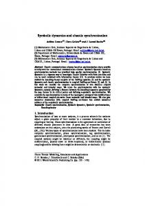
FIG. 2. The experimental chaotic attractor obtained using programmable analog devices 共FPAA兲.
Downloaded 15 Mar 2010 to 134.58.253.55. Redistribution subject to AIP license or copyright; see http://chaos.aip.org/chaos/copyright.jsp
013121-4
Chaos 16, 013121 共2006兲
Hulub et al.
FIG. 3. Experimental results: 共a兲 slave attractor; 共b兲 master attractor; 共c兲 error xm − xs.
Moreover, in order to overcome the inaccuracies due to the analog implementation, some slight modifications were made with respect to system 共4兲: the z variable is being multiplied by 0.46 when subtracted in the block SD5 and by 0.45 in the block GH1 instead of 0.5. These were determined experimentally, since we have observed that with the theoretical values of these parameters, the scrolls corresponding to the negative saturated plateau of f共y ; k2 , h2 , p2 , q2兲 were not present. These modifications are needed to compensate offset and inaccuracies of the analog device. All four CABs within FPAA2 were used, for this reason it was necessary to use a second FPAA, indicated as FPAA1. Here, the transfer function TF5 implementing f共x ; k1 , h1 , p1 , q1兲 was included. The sampling frequency chosen is 100 kHz, except for the two CAMs TF4 and TF5, which are driven by two clocks: one equal to 100 kHz and the second equal to 1.6 MHz. The experimental chaotic attractor obtained is shown in Fig. 2, which shows 160 000 recorded samples with a sampling frequency of 100 kHz 共which correspond to 1.6 s兲.
III. SYNCHRONIZATION BETWEEN TWO FPAA CIRCUITS
Synchronization between two 3 ⫻ 3 scroll chaotic circuits has been implemented by using a linear feedback topology. It is well known in fact that this master-slave technique allows two chaotic circuits to be synchronized, despite the dependency of chaotic systems on their initial conditions. Let us consider two 3 ⫻ 3 chaotic systems. The master system is described by Eqs. 共3兲, while the slave system is described by the following equations including the feedback error terms:15,16 x˙s = y s − 5f共y s ;k2,h2,p2,q2兲 + xm − xs , y˙ s = 0.5zs + y m − y s ,
共5兲
z˙s = − xs − y s − 0.5zs + 5f共xs ;k1,h1,p1,q1兲 + 5f共y s ;k2,h2,p2,q2兲 + zm − zs , where the subscripts m and s refer to master and slave, re-
FIG. 4. Experimental results: 共a兲 xm vs xs without feedback of the error; 共b兲 xm vs xs with feedback of the error; 共c兲 trend of the signal xm.
Downloaded 15 Mar 2010 to 134.58.253.55. Redistribution subject to AIP license or copyright; see http://chaos.aip.org/chaos/copyright.jsp
013121-5
FPAA 3 ⫻ 3 Grid scroll chaotic circuits
spectively. The phase-plane projections of the attractors of master and slave systems and the synchronization error are shown in Fig. 3. Figure 4共a兲 shows xm versus xs for the case in which the error is not fed back in the slave system, while Fig. 4共b兲 shows xm versus xs when the two circuits are synchronized. Fig. 4共c兲 shows the trend of xm. It can be noticed that the error signal has values less than 50 mV. IV. CONCLUSIONS
Based on equations presented in Ref. 1, a new chaotic circuit has been introduced in this paper. This circuit is a 3 ⫻ 3 grid scroll chaotic attractor. With the same approach based on FPAA, other grid scroll chaotic attractors could be easily implemented. Their ease in programming and their reprogrammability make FPAA a good platform for testing and immediate implementation of dynamic circuits. ACKNOWLEDGMENTS
This work was partially supported by the Italian “Ministero dell’Istruzione, dell’Università e della Ricerca” 共MIUR兲 under the Firb project RBNE01CW3M and by EU under the COST ACTION B27 ENOC. 1
J. Lü, G. Chen, X. Yu, and H. Leung, “Design and analysis of multiscroll chaotic attractors from saturated function series,” IEEE Trans. Circuits Syst., I: Fundam. Theory Appl. 51, 2476–2490 共2004兲. 2 L. O. Chua, “The genesis of Chua’s circuit,” Arch. Elektr. Uebertrag. 46, 250–257 共1992兲. 3 J. A. K. Suykens and J. Vandewalle, “Generation of n-double scrolls 共n = 1 ; 2 ; 3 ; 4 ; . . . 兲,” IEEE Trans. Circuits Syst., I: Fundam. Theory Appl. 40, 861–867 共1993兲.
Chaos 16, 013121 共2006兲 4
J. A. K. Suykens, A. Huang, and L. O. Chua, “A family of n-scroll attractors from a generalized Chua’s circuit,” AEU, Int. J. Electron. Commun. 51, 131–138 共1997兲. 5 P. Arena, S. Baglio, L. Fortuna, and G. Manganaro, “Chua’s circuit can be generated by CNN cells,” IEEE Trans. Circuits Syst., I: Fundam. Theory Appl. 42, 123–125 共1995兲. 6 P. Arena, S. Castorina, L. Fortuna, M. Frasca, and A. Rizzo, “An integrated Chua’s cell for the implementation of Chua’s array,” Int. J. Bifurcation Chaos Appl. Sci. Eng. 14, 93–106 共2004兲. 7 P. Arena, S. Baglio, L. Fortuna, and G. Manganaro, “Generation of n-double scrolls via cellular neural networks,” Int. J. Circuit Theory Appl. 24, 241–252 共1996兲. 8 K. S. Tang, G. Q. Zhong, G. Chen, and K. F. Man, “Generation of n-scroll attractors via sine function,” IEEE Trans. Circuits Syst., I: Fundam. Theory Appl. 48, 1369–1372 共2001兲. 9 M. E. Yalcin, J. A. K. Suykens, J. Vandewalle, and S. Ozoguz, “Families of scroll grid attractors,” Int. J. Bifurcation Chaos Appl. Sci. Eng. 12, 23–41 共2002兲. 10 J. Lü, F. Han, X. Yu, and G. Chen, “Generating 3-D multiscroll chaotic attractors: A hysteresis series switching method,” Automatica 40, 1677– 1877 共2004兲. 11 G. Kolumbàn, M. P. Kennedy, and L. O. Chua, “The role of synchronization in digital communications using chaos—Part I: Fundamentals of digital communications,” IEEE Trans. Circuits Syst., I: Fundam. Theory Appl. 44, 927–936 共1997兲. 12 L. Fortuna, M. Frasca, and A. Rizzo, “Chaotic pulse position modulation to improve the efficiency of sonar sensors,” IEEE Trans. Instrum. Meas. 52, 1809–1814 共2003兲. 13 P. Arena, L. Fortuna, M. Frasca, G. Lo Turco, L. Patané, and R. Russo, “Perception-based navigation through weak chaos control,” Proceedings of the IEEE 44th Conference on Decision and Control, 2005. 14 Anadigm 2005, available on-line, www.anadigm.com 15 M. Hasler, “Synchronization principles and applications,” Circuits and Systems Tutorials, IEEE ISCAS’94 共IEEE Press, New York, 1994兲, pp. 314–327. 16 S. Boccaletti, J. Kurths, G. Osipov, D. L. Valladares, and C. S. Zhou, “The synchronization of chaotic systems,” Phys. Rep. 366, 1–101 共2002兲.
Downloaded 15 Mar 2010 to 134.58.253.55. Redistribution subject to AIP license or copyright; see http://chaos.aip.org/chaos/copyright.jsp