INTERNATIONAL JOURNAL OF SCIENTIFIC & TECHNOLOGY RESEARCH VOLUME 3, ISSUE 5, May 2014
ISSN 2277-8616
Implementation Of An Automatic Induction Motor Starter With Delay Using Microcontroller Agbo D. O., Kureve D. T, Shittu D. H Abstract: It is well understood that induction motors draw higher currents during their starting operations than is the case under full load running conditions. Since the early days of induction motor availability, starting methods other than Direct-on-Line have been used, and in some cases mandated by Utilities, to reduce the effect of these high starting currents on the electrical distribution network. What is generally not recognized is the existence of short duration inrush currents, which greatly exceed these starting currents. Furthermore, the introduction of complex starting methods to reduce starting currents is often compromised by other unanticipated inrush currents introduced by the starting system itself, unless special precautions are taken. This paper implements a device that protects three phase induction motor from inrush currents on the distribution system, as well as on the motor protection components using PIC16F84A Microcontroller. Keywords: Induction Motor, Microcontroller, motor protection, currents, MPLAB, Direct on line, distribution system. ————————————————————
1. INTRODUCTION Induction motors are popular due to their low-cost, sturdy construction, fast pick-up, low maintenance expenditure and good efficiency. The DOL (direct-on-line) starters and star/delta starters used for starting and running of induction motors provide coarse type of protections against voltage fluctuations and single phasing. Induction motors are very sensitive to low voltage and single phasing during which they draw a heavy current and can burn out unless switched of within few seconds of occurrence of such conditions. This makes the requirement of a sensitive protective device essential to avoid burning of induction motors under such conditions. The circuit of an automatic starter, incorporating the important features given below, is described here. It is meant to be used in conjunction with a DOL starter. Automatic start on resumption of proper conditions Single phasing prevention 24-hour programmable off timer (on completion of actual runtime of the motor). An induction or asynchronous motor is a type of AC motor where power is supplied to the rotor by means of electromagnetic induction, rather than a commutator or slip rings as in other types of motor. These motors are widely used in industrial drives, particularly poly-phase induction motors, because they are rugged and have no brushes. Single-phase versions are used in small appliances. Their speed is determined by the frequency of the supply current, so they are most widely used in constant-speed applications, although variable speed versions, using variable frequency drives are becoming more common. The most common type is the squirrel cage motor.
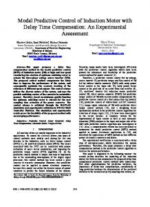
2. METHOD The block diagram of the system is depicted in Fig. 1.0. The embedment of a microcontroller into the system makes it a standalone system that is capable of taking decisions to keep the system functioning properly. The microcontroller receives inputs signals from the three phase mains which is been step down by step-down transformers, depending on the input the microcontroller receives, it either takes decision to switch on the relays or switch off the relays. Three Phase A.C Power Supply
Relay Switch
Three Rectifier
Induction motor
Programmable Timer (555 timer or Microcontroller)
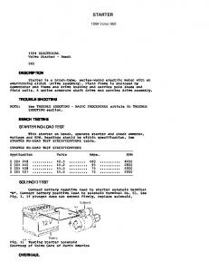
Fig.1.0: The automatic induction motor starter with programmable timer When the system is first switched on, it waits for 30 seconds to make sure the power source is stable and starts monitoring. By switching ON or OFF of the relays, the microcontroller also turn on LEDs and the color of LED, being lit ON, indicates which the three phases is ON or OFF. The schematic diagram of the automatic three phase direct starter controller system is given in Fig. 2.0. The microcontroller used for the project is the PIC16F84A [5]. The microcontroller takes inputs from the three mains continuously via step-down transformer. Under the control of the program written in the microcontroller’s memory, the microcontroller turns either Red or Green LEDs and turns the three relays ON or OFF.
__________________________
Agbo D. O., Kureve D. T, Shittu D. H Department of Electrical and Electronics Engineering, University of Agriculture, P.M.B. 2373, Makurdi, Nigeria. Email:
[email protected] 47 IJSTR©2014 www.ijstr.org
INTERNATIONAL JOURNAL OF SCIENTIFIC & TECHNOLOGY RESEARCH VOLUME 3, ISSUE 5, May 2014
ISSN 2277-8616
V1
1
TR1
D1
C0
D4
2
TRAN-2P2S
VI 7805
D2
VO
3
GND
V3PHASE
F1
C1
F2
F3
U3
D3 C0(1)
D5 TR2
D8
D8(K)
VI
C5
2
TRAN-2P2S
TRAN-2P2S
7812
D6
D7
D9
D12
VO
3
GND
1
R_Phase
R1
Phase_Y
D12(K)
R3
Phase_B
R2
R5
Phase_R
R4
R6
D11
C3
R_Phase
XTAL
R10
R11
Y_Phase
4
OSC1/CLKIN OSC2/CLKOUT MCLR
R15
RA0 RA1 RA2 RA3 RA4/T0CKI
RL3
D13
17 18 1 2 3 6 7 8 9 10 11 12 13
Phase_R Phase_Y Phase_B
R7
R8 R9
Q2
Q3 Q1 +88.8
RB0/INT RB1 RB2 RB3 RB4 RB5 RB6 RB7
RM D14
RL2
U1 16 15
R13
B_Phase
R12 RL1
C2
B_Phase
U2
TR3 D10
Y_Phase
C4
PIC16F84A
THREE-PHASE INDUCTION MOTOR Q4
Q5 R16
R14
Fig. 2.0: Complete Circuit diagram of a Three phase Induction Motor
48 IJSTR©2014 www.ijstr.org
INTERNATIONAL JOURNAL OF SCIENTIFIC & TECHNOLOGY RESEARCH VOLUME 3, ISSUE 5, May 2014
The transistors are turned on depending on the state of each AC supply phase. The voltage at each phase determines which of the transistor will trigger on. Using the requirements for the saturation of the BJT expressed as
F I B IC ..............(1) Under the condition in equation 1, the transistors (Q1, Q2, Q3, Q4, Q5, Q6, Q7) will turn on. The transistor (Q) will turn on when
Rg Rb
F R1 VCC VBEsat VCC VCEsat
.............(2)
3.
RESULTS AND DISCUSSIONS
The program for the microcontroller was written in Assembly Language which is attached as Appendix 1 and was then built into an executable Hex file using the MPLAB IDE Version 8.50 and the embedded MPASM assembler [6], [7]. A software simulation was carried out with the simulator built into the MPLAD IDE to ensure that the program variables and registers changed as desired. The program required few registers but the output ports (PORTA and PORTB) were observed to have the correct values. The circuit shown in Fig. 2.0 was then built in Vero board, which was tested using three phase ac mains and the output was connected to 220 V, 100 Watts bulb. The microcontroller program was observed and it gave the required outputs. Table 1: Sensor Conditions and Microcontroller Decisions
Since we are using transformer of 240/12 volts and need a voltage of 5volts (nominal input voltage of microcontroller) Figure 3.0 gives the flow chart of the program executed by the microcontroller. As indicated in the flow chart the microcontroller polls the input.
Phase Conditions P1 P2 P3
Check for port pin of the Microcontroller
L
L
Only one phase is on
H
H
L
Two phases are on
H
H
H
All the three phases are on
4.
Red LED ON and the relays are turned off Red LED ON and the relays are turned off Green LED ON and the relays are turned off
CONCLUSION
An automatic over and under voltage protector system has been implemented using induction motor starter which is neccessitated by the need to monitor the voltage supply to equipments and appliances and consequently protect them from the danger of being damaged due to voltage fluctuation. Based on the theoretical analysis, design and testing of this work, the following conclusions are made: 1. Since switching is automatic, the device is no doubt being used as an automatic voltage protector. 2. The display of the monitored voltage is indicated simply by LEDs, which can be easily seen and understood by all. 3. The assembly unit is very compact and portable and can be easily incorporated into appliancies or equipments. 4. The cost of constructing this project is relatively low as compared to the important function it performs. It can therefore be easily commercialised.
NO
Yes
Is pin_2 ON ?
Output
Note that in Table 1, L = Low Logic Level Signal and H = High Logic Level Signal, P1 = Phase 1, P2 = Phase 2, P3 = Phase 3
NO
Yes
Is pin_1 ON ?
Indication
H
Start
Is pin_0 ON ?
ISSN 2277-8616
NO
Yes Delay start of induction motor by 20seconds
Turn ON relays
Fig.3.0: Flow chart of the three induction motor starter with automatic programmable timer 49 IJSTR©2014 www.ijstr.org
INTERNATIONAL JOURNAL OF SCIENTIFIC & TECHNOLOGY RESEARCH VOLUME 3, ISSUE 5, May 2014
5. REFERENCES [1].
Agbo, O. D and G. J. Liambee, Design And Construction Of An Automatic Overvoltage And Under voltage, Electrical and Electronic Engineering Department, University Of Agriculture, Makurdi (Unpublished).
[2].
http//www.opamp.htm.Operational Amplifier Basics (01/11/2008).
[3].
MPLAB IDE User’s Guide, 2004. Microchip Technology Inc, 2355 West Chandler Blvd., Chandler, Arizona, U.S.A.
[4].
MPASM Assembler, MPLINK Object Linker, MPLIB Object Librarian, Microchip Technology Inc, 2355 West Chandler Blvd., Chandler, Arizona, U.S.A.
[5].
User’s Guide, 2005. Microchip Technology Inc, 2355 West Chandler Blvd., Chandler, Arizona, U.S.A.
[6].
MPLAB PM3 Programmer User’s Guide, 2006. Microchip Technology Inc, 2355 West Chandler Blvd., Chandler, Arizona, U.S.A.
__CONFIG _CP_OFF & _WDT_OFF & _PWRTE_ON & _XT_OSC ORG 0x00 BCF STATUS, RP0 CLRF PORTA clearing output data latches BSF STATUS, RP0 MOVLW B'11111111' data direction MOVWF TRISA
;
Set
RA
as
; ; Initialize PORTB by
BSF STATUS, RP0 MOVLW B'00000000' data direction
; Select Bank 1 ; Value used to initialize
MOVWF TRISB
;
Set
RB
BSF STATUS,5 MOVLW 0x00 MOVWF PORTB BCF STATUS,5
;Turn to Bank 1 ; ; ;Return to Bank 0
as
outputs START
[8].
PIC16F84A datasheet, 2006. Microchip Technology Inc, 2355 West Chandler Blvd., Chandler, Arizona, U.S.A.
MAIN
[9].
Theraja, B. L and A. K. Theraja, A Text Book Of Electrical Technology. S. Chand Company Ltd. New Delhi, pp. 851-918, 2001.
SWITCH1 BTFSC PORTA, 0 GOTO SWITCH2 GOTO OUTPUT1
[10].
Fernando, E. V, Peres and P. A. Ramon,. Microcontrollers “Fundamental and Applications with PIC.” CRC Press, Taylor and Francis Group, New York, 2009.
[11].
2SC4204 NPN transistor datasheet, 2005. Sanyo Electric Co. Ltd, Tokyo, Japan.
PROCESSOR PIC16F84A #Include "p16f84A.inc"
; Select Bank 1 ; Value used to initialize
BCF STATUS, RP0 CLRF PORTB clearing output data latches
Okolo I. K. Design And Construction Of A Digital Distance Device Using A Microcontroller, Electrical/Electronic Engineering Department, University Of Agriculture, Makurdi, (Unpublished).
Assembly Programming Language ;Author : AGBO ;File Name : A_IM_STARTER.asm ;TITLE : "INDUCTION MOTOR STARTER WITH AUTOMATIC TIME DELAY " ;Date : 3RD NOV. 2012 ;Version : 1.0 ;Debugged : 29 NOV. 2012 ;********************************************************* ;********Processor Declaration and Configuration*************
; ; Initialize PORTA by
inputs.
[7].
6. APPENDIX 1
ISSN 2277-8616
NOP
SWITCH2 CALL DELAY ; CALLING DEBOUNCE BTFSC PORTA, 1 GOTO SWITCH3 GOTO OUTPUT1 SWITCH3 CALL DELAY ; CALLING DEBOUNCE BTFSC PORTA, 2 GOTO OUTPUT GOTO OUTPUT1 OUTPUT CALL DELAY20MSEC DEBOUNCE BSF PORTB, 1 ON(UNRESET) BSF PORTB, 2 ENGINE BSF PORTB, 3 ENGINE BSF PORTB, 6 ENGINE
; ;
CALLING LED
GREEN
;
ENGAGING
CAR
;
ENGAGING
CAR
;
ENGAGING
CAR
50 IJSTR©2014 www.ijstr.org
INTERNATIONAL JOURNAL OF SCIENTIFIC & TECHNOLOGY RESEARCH VOLUME 3, ISSUE 5, May 2014
BCF PORTB, 7 OFF(UNRESET) GOTO START instruction
;
LED
GREEN
IS
; if it is 1 skip this
OUTPUT1 CALL DELAY20MSEC BSF PORTB, 7 OFF(UNRESET) BCF PORTB, 1 ON(UNRESET) BCF PORTB, 2 ENGINE BCF PORTB, 3 ENGINE BCF PORTB, 6 ENGINE GOTO START
GOTO deld DECFSZ
; 0x1C,1
;Decrment file 1C till
GOTO deld DECFSZ
; 0x1A,1
;Decrement file 1A till
GOTO deld
;
zero
zero ; ; ;
LED
GREEN
LED
IS
GREEN
;
ENGAGING
CAR
;
ENGAGING
CAR
;
ENGAGING
CAR
DELAY MOVLW .2 MOVWF
ISSN 2277-8616
;Make deld repeat two times 0x1A ;
DELAY20MSEC MOVLW 0x02 times MOVWF deld1 DECFSZ 1B till zero GOTO deld1 DECFSZ 1C till zero GOTO deld1 DECFSZ 1A till zero GOTO deld1 RETURN
;Make deld repeat two 0x1A
;
0x1B,1
;Decrement file ;
0x1C,1
;Decrment file ;
0x1A,1
;Decrement file ;
deld DECFSZ
0x1B,1
;Decrement file 1B till
END
zero
The Automatic Induction Motor Starter With With Programmable Timer
51 IJSTR©2014 www.ijstr.org