Tarek BENMILOUD, Abdelhafid OMARI University of Sciences and Technology of Oran (1), (2)
Improved Adaptive Flux Observer of an Induction Motor with Stator Resistance Adaptation Abstract. In this paper, an improved scheme of adaptive flux observer of induction motor is proposed. This adaptive observer is used with fieldoriented control of induction machine. It is based on using induction motor model with the estimation of the load torque besides the estimation of the stator resistance. The robustness of this observer with respect to the variation of the stator resistance. The performances of the proposed adaptive observer were compared to those of the classical one via numerical simulation. The obtained results show the effectiveness of the proposed scheme. Streszczenie. Zaproponowano ulepszony adaptacyjny system obserwatora strumienia w silniku indukcyjnym. Bazuje on na modelu w którym określa się moment obciążenia i rezystancję stojana. jest proponowane dla pola zorientowanych kontroli indukowanie maszyny. (Ulepszony obserwator strumienia w silniku indukcyjnym z pomiarem rezystancji stojana)
Keywords: induction motor, adaptive flux observer, direct field-oriented control. Słowa kluczowe: obserwator strumiena, silnik indukcyjny.
Introduction At the present time, the direct field oriented control (FOC) technique is widespread used in high performance induction motor (IM) drives [1], [2]. It allows, by means of coordinate transformation, to separate the electromagnetic torque control from the rotor flux one, and, hence to manage induction motor as dc motor. Such control method needs the knowledge of the rotor flux, which is not directly measurable. In order to avoid expensive sensors, rotor flux observers are commonly used [3]. Given that the effectiveness of the control strategy is based on right rotor flux detection, the drive performance is strictly connected to these of the rotor flux observer [4]. Therefore, the performances of the observer, in terms of stability, accuracy and robustness, critically influence those of the drive. In this work, we propose to improve the robustness and performances of the adaptive flux observer of induction motor, using the estimation of the load torque as an added input for the adaptive observer. The estimation of the load torque will give best estimation of the rotor flux, because the adaptive observer will have more similarity to the real model of the induction motor. This paper is organised as follows. In Section II, the state model of IM is presented. Section III presents the improved adaptive flux observer. In Section IV, the effectiveness of the proposed scheme is discussed via simulation results. Section V presents the final remarks. Direct Field Oriented Control Modern control techniques often require a state-space model [5].
K 1 isd s i sq T rd p r K rq L u sd r s isd 1 K u sq i isq p r K rd rq i s sd T L r s (1) sq 1 M i sd rd ( s p r ) rq rd Tr Tr rq 1 M i sq ( s p r ) rd rq Tr Tr r p 2 M f p (rd isq rq isd ) r TL J Lr J J
The state-space representation of the IM depends on the choice of the reference frame ( , ) or (d,q) and on the state variables selected for the electric equations. We write the equations in the frame (d, q) because it is the most general and most complex solution, the frame ( , ) being only its one particular case. The IM mathematical model [2, 3, 6, 7, 8] in space vector notation, established in d-q coordinate system rotating at synchronous speed s is given by the Eq (1). Where (2)
1
M2 , R r 1 1 R s K L r , M Ls Ls Lr
The matrix representation of the state model of IM is [9, 10]: (3)
x A x B u ,
y C x
Here A is the motor parameter matrix, B is the input matrix C the output matrix, and Y is the output vector. The state variables are the two components of stator current, (isd, isq) the two components of the rotor flux (rd, rq), and the electrical rotor speed r. The vector input u is represented by the stator voltages vsd, vsq and the load torque TL which can be considered as the third input of the IM. We have therefore: (4)
u sd u u sq T L
There are many categories of vector control strategies. We are interested in this study to the so-called DFOC. We have shown in Eq (1), that the electromagnetic torque expression, in the dynamic regime, presents a coupling between stator current and rotor flux. The main objective of the vector control of is, to independently control the torque and the flux. This is done by using a d-q rotating reference frame synchronously with the rotor flux space vector. The daxis is aligned with the rotor flux space vector. Under this condition we have: rd r and rq 0 . The torque equation becomes: (5)
Te p
M rd isq Lr
PRZEGLĄD ELEKTROTECHNICZNY (Electrical Review), ISSN 0033-2097, R. 87 NR 9a/2011
325
It is right to adjust the flux while acting on the component ids of the stator current and to adjust the torque while acting on the isq component. We have two variables of action then as in the case of a DC machine. Combining equations (1) and (2), we obtain the following d and q-axis stator currents : (6) i ds 1 Tr s r , i Tr qs sl r M M L
r where Tr is the rotor constant; Tr R , M and r
sl are
mutual inductance and sleeping pulsation. Using Eq (1), we obtain the voltage equations [1]:
M p r Ls s isq Lr M usq Rs Ls s isq Ls s isd s r Lr
usd Rs Ls s isd
(7)
Rˆ s (e is iˆis e is iˆis ) Rˆ s
(14)
Therefore, the following proportional and integral adaptive scheme is used practically in order to improve the response of the rotor resistance estimation.
(15) Rˆ s K p (e i s iˆis e i s iˆis ) K i (e i s iˆi s e i s iˆi s )
The rotor resistance is made proportional to the stator resistance which is identified adaptively, because both resistances change with the operating temperature.
s wr
From Eq (13), we can find the following adaptive scheme for rotor resistance estimation.
where K p , K i are arbitrary positive gains.
These equations are functions of some structural electric parameters of the IM (Rs, Rr, Ls, Lr, Lm), which are in reality approximate values. We will come back thereafter to the influence of the bad knowledge of most interest parameter (Tr=Lr/Rr) on the control of the machine [3]. The rotor flux amplitude can be obtained by solving Eq. (1), and its spatial position is given by: (8)
where e i s i s iˆs , e i s i s iˆs
M isq dt Tr r
R r nom ˆ Rˆ r Rs R s nom
(16)
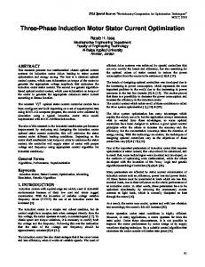
R r nom , R s nom nominal values of rotor and stator resistances. b. Proposed Adaptive flux observer In this work, we propose to add the estimation of the load torque TˆL to the scheme of the adaptive flux observer given by Eq (9). As it is shown in Fig. 1, the estimation of the load torque (presented in dotted line) is realised by the product of the error
Improved Adaptive Flux Observer a. Adaptive flux observer The adaptive state observer [9, 11, 12], which estimates the rotor flux, is given by the following equation: (9)
xˆ Aˆ (Rˆ r ) xˆ B u s G (i s iˆs )
,
estimated speed of the IM) with an appropriated gain K 0 : ˆm TˆL K0 e with e m
(17)
u us sd usq
R s I 0 2 X2 A Aˆ A Ls 0 2X 2 0 2 X 2
e x xˆ and
R
2 s
is a positive constant. The time derivative of V becomes: (13) V 2 e T ( A G C ) e 2
326
B
Rs
Ls
ˆr ˆm
is
C iˆs
Rˆ s
Rs e i s iˆs e i s iˆs 2 Rˆ s
-
-
e m
ei
Aˆ Rˆ s estimat
Improved Adaptive flux observer
e ( A G C ) e A xˆ
V eT e
Induction Motor
G
Now, we define the following Lyapunov function candidate [8] (12)
m
us
TˆL
In order to derive the adaptive scheme, Lyapunov’s theorem is utilized. From Eq (3), the error of the stator current is described by the following equation [10, 13]:
where
m
m
adjustment of the value of rotor resistance. The input vector of this observer is composed by the two stator voltages:
(11)
(between the real and the
yˆ C xˆ
where means the estimated value and G is the observer gain matrix which is chosen to allow stability of (9). This adaptive observer gives the estimation of the rotor flux using the estimation of the stator currents iˆs and the
(10)
em
K0
Fig.1. Scheme of improved adaptive flux observer
The estimated load torque TˆL will be the third input of the state observer of rotor flux. The equation of the new proposed adaptive state observer is: usd (18) xˆ Aˆ ( Rˆ s ) xˆ B usq G (is iˆs ) , yˆ C xˆ Tˆ L
s
PRZEGLĄD ELEKTROTECHNICZNY (Electrical Review), ISSN 0033-2097, R. 87 NR 9a/2011
20
0
-20
0
1
2
3
4
5
6
7
8
Figure 6 shows, good performances of observation of the electromagnetic torque; we note limited peaks after applications of load torque. As shown in Fig. 7, the drive torque follows the load torque when the speed is constant. During an increase or decrease in the speed, a difference of 0.3 Nm appears between the two torques. 0.5 0.4
Speed error tracking [rad/s]
Speed [rad/s]
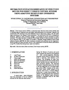
Simulation results Simulations, using MATLAB Software Package, have been carried out to show the effectiveness of the proposed observer. Direct field oriented control with the proposed adaptive flux observer is illustrated by a computer simulation shown in the block diagram of Fig. 3. Classical Proportional-Integral controllers are used for speed, flux and stator current loops. The sampling time of simulation is set to 1 ms. The IM parameters used in simulation are given in Table I. The reference trajectories of speed, flux, and stator currents are given in Fig. 3. Flux reference is set to its rated value of 1 Wb.
0.1 0 -0.1 -0.2 -0.3 -0.4 -0.5 0
1.5
1
2
3
4
6
7
8
9
Fig.3. Speed error tracking (improved adaptive observer)
0.5 0
5
Time [s]
1
0
1
2
3
4
5
6
7
8
9
1.5
0 0
1
2
3
4
5
6
7
8
9
Time [s]
Fig.2. Reference trajectories
This benchmark shows that the load torque appears at the low speed (15.7 rad/sec), and the load torque is varied at 1.3 s from 0 to 10 Nm. Thus we have a positive torque for both cases; for positive speed and a negative speed. We study sensitivity to stator resistance disturbances for an increase of 100 % on the stator resistance Rs. Table 1. The parameters of the induction motor Paramter Notation Value Rotor resistance 3.805 Ω Rr Stator resistance 4.85 Ω Rs Mutual inductance 0.258 H M Stator inductance 0.274 H Ls Rotor inductance 0.274 H Lr 2 Rotor inertia 0.31 Kg/m Jm Pole pair 2 p -1 Viscous friction coef 0.008 Nm sec rad fm Mechanical power 1.5 KW Pmax Nominal voltage 220 V Vn Nominal current 3.1 A Isn Nominal speed 1500 Nm Ωn
First, we use the proposed adaptive flux observer given by equation (24), associated to the direct oriented control of IM, with the increase of 100 % in the value of the stator resistance Rs. The increase in stator resistance is made in form of ramp at the time t = 1.5 s. Secondly, we use a classic observer (without the adaptation of the stator resistance) with the same increase of the stator resistance at the same time (t = 1.5 s). Fig. 4 shows that speed tracks perfectly the reference without overtaking. The drop in speed after the application or the elimination of the load torque is almost zero. The control strategy allows keeping the same regulation performances despite the change of the value of the stator resistance. Figure 5 shows high performance of the tracking of the flux. The desired flux remains constant in the IM to satisfy the objectives of the field-oriented control.
1
0.5
0
-0.5
-1
-1.5
0
1
2
3
4
5
6
7
8
9
Time [s]
Fig.4. Rotor flux error tracking (improved adaptive observer) 5
Torque estimation [Nm]
5
Rotor flux correction error [Wb]
10
0
-5
-10
-15
0
1
2
3
4
5
6
7
8
9
Time [s]
Fig.5. Observation error of ELM torque (improved observer) real torque load torque
14 12 10
Torque [Nm]
Flux [Wb]
0.2
9
2
Torque [Nm ]
0.3
8 6 4 2 0 -2
0
1
2
3
4
5
6
7
8
9
Time [s]
Fig.6. Motor and load torques (improved adaptive observer)
PRZEGLĄD ELEKTROTECHNICZNY (Electrical Review), ISSN 0033-2097, R. 87 NR 9a/2011
327
Fig.7. Schematic diagram of Direct field oriented control of IM with improved adaptive flux observer
Rotor flux estimation error [Wb]
1.5
1
0.5
0.5 0.4
Speed error tracking [rad/s]
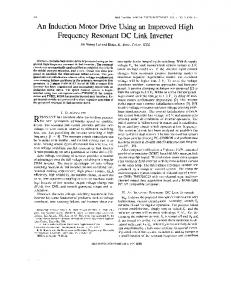
Figure 8 shows, a high performance of estimation of the rotor flux using the proposed adaptive observer; the observation error of flux is almost zero. Figure 9 illustrate a good estimation of the value of the stator resistance with rapidity and precision, we note a considerable drop to the start of the control.
0.3 0.2 0.1 0 -0.1 -0.2 -0.3 -0.4
0
-0.5 -0.5
0
1
2
3
4
5
6
7
8
9
Time [s]
Fig.10. Speed error tracking (classical observer)
-1
1.5
-1.5 0
1
2
3
4
5
6
7
8
9
Fig.8. Observation error of the rotor flux (improved adaptive observer)
Figure 10 show that speed tracks perfectly the reference without overtaking. The drop in speed after the application or the elimination of the load torque is almost zero. In Figure.11 shows high performance of the tracking of the flux. The desired flux remains constant in the IM
Rotor flux correction error [Wb]
Time [s] 1
0.5
0
-0.5
15
Stator resistance estimation [Ohm]
Rr Rr est
-1
0
1
2
3
4
5
6
7
8
9
Time [s] 10
Fig.11. Rotor flux correction error (classical observer)
Figure 12 shows a good tracking of the electromagnetic torque. Figure 13 shows a bad estimation performances of estimation of the flux with considerable estimation error when we hace variation in the value of the stator resistance (after t=1.5 s).
5
0 0
1
2
3
4
5
6
7
8
9
Time [s]
Fig.9. Observation of the rotor resistance (improved adaptive observer)
328
PRZEGLĄD ELEKTROTECHNICZNY (Electrical Review), ISSN 0033-2097, R. 87 NR 9a/2011
REFERENCES real torque load torque
14 12
Torque [Nm]
10 8 6 4 2 0 -2
0
1
2
3
4
5
6
7
8
9
Time [s]
Fig.12. Motor and load torques (classical observer)
Rotor flux estimation error [Wb] Rotor flux estimation error [Wb]
0.5
0
-0.5
-1
0
1
2
3
4
5
6
7
8
9
Time [s]
Fig.13. Rotor flux estimation error (classical observer)
Conclusion In this paper, we presented a new scheme of adaptive flux observer of induction motor, based on the correction of the value of the stator resistance and the estimation of the load torque. The estimation of the torque is based on the use of the error between real and estimated speed of induction motor, this will have to improve the performances of the adaptive flux observer. The results show that the proposed adaptive observer offers better performances while tracking the speed and the flux, even in presence of stator resistance variation. Future works concern real true implementation of the proposed scheme to validate these theoretical results.
[1] J.P. Caron, J.P. Hautier. (1995): Modeling and Control of Induction Machine. Technip Edition [2] M. A. Ouhrouche and C. Volat. (2000): Simulation of a Direct Field-Oriented Controller for an Induction Motor Using Matlab/ Simulink. Proceeding of the IASTED International Conference Modelling and Simulation - Pittsburgh, Pennsylvania, USA. [3] M. Alamir. (2002): Sensitivity analysis in simultaneous state/ parameter estimation for induction motors. Int. J. of Control, vol. 75, n°10, pp. 753-758. [4] M. Alexandru , R. Bojoi, G. Ghelardi, S.M.Tenconi. (2002): An AC motor closed loop performances with different rotor flux observers. MCFA Annals, Vol III, pp.1-3. [5] T. Van Raumer J.M. Dion, L. Dugard and J.L.Thomas (1994): Applied nonlinear control of an induction motor using digital signal processing. IEEE Trans. Contr. Syst. Technol, Vol. 2, No. 4, pp. 327–335.J. [6] Soltani, Y.Abdolmaleki and M. Hajian. (2005): Adaptive fuzzy sliding-mode control of speed sensorless universal field oriented induction motor drive. Iranian Journal of Science & Techno-logy, Transaction B, Engineering, Vol. 29, No. B4. [7] A. Bouhenna, A. Mansouri, M. Chenafa, A. Belaidi. (2008): Feedback Gain Design Method for the Full-Order Flux Observer in Sensorless Control of Induction Motor. Int. J. of Computers, Communications & Control, IJCCC, Vol. III , No. 2, pp. 135-148. [8] A. Mansouri, M. Chenafa, A. Bouhenna and E. Etien. (2004): Powerfull nonlinear observer associated with field-oriented control of an induction motor. Int. J. Appl. Math. Comput. Sci, Vol. 14, No.2, 209–220. [9] F. Khoucha, K. Marouani, A. Kheloui, K. Aliouane. (2004): A DSP-based Discrete Space Vector Modulation Direct Torque Control of Sensorless Induction Machines. NORPIE, Nordic Workshop on Power and Industrial Electronics, Trondheim, Norway. [10] H. Kubota and K. Matsuse. (1994): Speed sensorless fieldoriented control of induction motor with rotor resistance adaptation. IEEE Trans. Ind. Appl., vol. 30, no. 5, pp. 1219– 1224. [11] T. Pana and C. Rusu. (2002): Speed and rotor flux estimation in speed sensorless control of induction motor. The annals of "Dunarea Dejos" University of Galati Fascicle III, ISSN 1221454X. Electrothecnics, Electronics, Automatic Control, Informatics. [12] G. C. Verghese. and S.R. Sanders. (1988): Observers for flux estimation in induction machines. IEEE Trans. Ind. Electron., Vol. 35, No. 1, pp. 85–94. [13] M. O. Sonnaillon, G Bisheimer, Cristian De Angelo, G. García and J. Solsona. (2004): State estimation in electric motor drives with a reduced number of sensors. In Proc. VI International Conference of Industrial applications (INDUSCON), code COE_53, Joinville, Brazil. Authors: Mr. Benmiloud Tarek, University of Sciences and Technology of Oran, Departement of Electrotechnic, BP 1505, ElMnaouar, Oran Ageria. E-mail:
[email protected]; dr Omari. Abdelhafud, University of Sciences and Technology of Oran,Departement of Automatic, BP 1505, El-Mnaouar, Oran Ageria. E-mail:
[email protected].
PRZEGLĄD ELEKTROTECHNICZNY (Electrical Review), ISSN 0033-2097, R. 87 NR 9a/2011
329