Implementation of Interactive Database System for STEP-Geometric Data from Express Entities Chinta Someswara Rao
K Suresh Babu
Assistant Professor, Computer Science and Engineering, SRKR Engineering College, Bhimavaram, Andhra Pradesh, INDIA. E-mail:
[email protected]
Associate Professor, Mechanical Engineering, SRKR Engineering College, Bhimavaram, Andhra Pradesh, INDIA.
Dr.Adavi Balakrishna
Dr. D Nageswara Rao,
Professor, Mechanical Engineering, SRKR Engineering College, Bhimavaram, Andhra Pradesh, INDIA. E-mail:
[email protected]
Professor, Mechanical Engineering, AU College of Engineering, Andhra University, Visakhapatnam. INDIA.
Prof G V Padma Raju Professor Computer Science and Engineering, SRKR Engineering College, Bhimavaram, Andhra Pradesh, INDIA reason for this is because engineering applications have unusually complex information models. Often, the information models exist only as program language structures taken from a primary application, usually Computer Aided Design (CAD) systems. Without a welldefined model, subsequent applications must be modified whenever the primary application changes [1]. In practice, only small, highly focused, applications are ever developed by anyone other than the primary application vendor. The resulting situation is that only special-purpose databases, controlled by CAD vendors, are used to describe complex products. Designer and manufacturing engineers do not have any control over these product databases, which is clearly undesirable for strategic reasons. Also, applications that improve segments of a market cannot be applied to an industry that is locked into vertical applications. The dominance of special-purpose databases and verticallyintegrated applications is a major reason why the generalpurpose engineering database market remains small. Industry has begun to address this problem by developing standard engineering information models. The Standard for Product Data Exchange (STEP) contains formal descriptions of the information used by the engineering activities in a product lifecycle [2]. These models are the result of significant investments of time and expertise, and represent the agreement of many interested parties on the scope, content, and correctness conditions of the information. Due to above mentioned requirement, documenting engineering information models requires a formalism that can store and manage data from EXPRESS entities. This
Abstract— Today information systems have become the key factor of current computer based engineering applications. So database are designed to support data storage, processing, and retrieval activities related to data management, and they are the key to implementing engineering information models. However, the current mainstream databases are mainly used for business applications, some new engineering requirements challenge today’s database technologies and promote their evolvement. The main focus of this paper is to determining the requirements of a database for STEP-Geometry entities that supports integrity validation of versioned design artifacts through effective management of evolving constraints. In this paper develop a tool for separate and store the geometric data from STEP file using EXPRESS entities. Finally this tool operates around a version model that uses a well-defined configuration management strategy to manage and storage of geometric data. Keywords- Database, EXPRESS entity, Geometric Data, STEP
I.
INTRODUCTION
Design and manufacturing companies eager to integrate their engineering processes around product databases, but engineering databases are expensive and difficult to create. Integration around product databases can enable concurrent engineering, a process where multiple engineers work on different facets of a product concurrently. However, integrated product databases are yet to be common in industry in the EXPRESS entities perspective [1]. One
_____________________________________ 978-1-4244-5539-3/10/$26.00 ©2010 IEEE
285
•
paper presents a pleasant interactive environment to separate and store the geometric data from STEP file. II. BACKGROUND Databases in collaborative product development can be of different nature. Roughly a distinction can be made between (virtually) central (but actually heterogeneous) shared database, and distributed and non-shared databases. Shah et al. [3] use database technology to achieve integration. Engineering data have complex structures and are usually large in volume. But engineering design objects and their components are not independent. In particular, they are generally organized into taxonomical hierarchies. The specialization association is the well-known association. Also the part-whole association, which relates components to the compound of which they are part, is another key association in engineering settings. Database systems are the key to implementing information modeling. Engineering information modeling requires database support [4]. Engineering information modeling in databases can be carried out at two different levels: conceptual data modeling and logical database modeling. A. Conceptual data models Much attention has been directed at conceptual data modeling of engineering information [5]. Product data models, for example, can be viewed as a class of semantic data models (i.e., conceptual data models) that take into account the needs of engineering data [6]. Recently, conceptual information modeling of enterprises such as virtual enterprises has received increasing attention [7]. Generally speaking, traditional ER (entity-relationship) and EER (extended entity-relationship) can be used for engineering information modeling at conceptual level [8]. Features of conceptual data model include: • Includes the important entities and the relationships among them. • No attribute, primary key is specified.
All attributes, primary key for each entity are specified. • Foreign keys are specified. • Normalization occurs at this level. Nadjib Bouikni, et.al, [14] presented paper on multiple views management system for Concurrent Engineering (CE) and Product Lifecycle Management (PLM). PLM is an approach for controlling and exploiting product-related information throughout its lifecycle as needed by various business functions. CE integrates several disciplines contributing to product design. Both PLM and CE involve information sharing amongst disciplines having a specific point of view regarding the product. M. Hardwick and D. Loffredo discussed [15] the dominance of special-purpose databases and why vertically-integrated applications are a major reason for the general-purpose engineering database market to remain small. Industry has begun to address this problem by developing standard engineering information models. Databases are designed to support data storage, processing, and retrieval activities related to data management, and database systems are the key to implementing engineering information modeling. But the current mainstream databases are mainly designed for business applications not for STEP geometric data. III. DATABASE DESIGN Conceptual data models are generally used for engineering information modeling at a high level of abstraction. However, engineering information systems are constructed based on logical database models. So at the level of data manipulation, that is, a low level of abstraction, the logical database model is used for engineering information modeling. Here, logical database models are often created through mapping conceptual data models into logical database models. In this conversion uses a conceptual design for stores the geometric data from EXPRESS entities. A. Database Systems The implementations built using the MS Access, Oracle, DB2 database systems. In this section we present the characteristics of MS Access database systems. MS Access is the most widely used of the systems examined here. MS Access other relational systems such as Oracle and DB2 are used by engineering organizations to store and manage configuration control data. The strength of relational systems is in their ability to store large amounts of data in a highly normalized, tabular form, and to perform efficient queries across large data sets. Relational systems use SQL for both data definition and data manipulation.
B. Logical Database model Generic logical database systems used in engineering information modeling such as relational databases, nested relational databases, and object-oriented databases. Ahmed [9] proposed in his paper a KSS (Kraftwerk Kennzeichen System) identification and classification system was used to develop database system for plant maintenance and management. Arnalte and Scala [10] were built on top of a relational DBMS, an EXPRESS oriented information system for supporting information integration in a computerintegrated manufacturing environment. Goh et al [11] have studied Object-oriented databases for STEP/EXPRESS. Based on the comparison with relational databases, the selections and characteristics of the object-oriented database and database management systems (OODBMS) in manufacturing were discussed in Zhang [12]. Also, the formal transformation of EER and EXPRESS-G was developed in Ma et al. [13]. Features of a logical data model include: • Includes all entities and relationships among them.
B. Geometric Data Mapping To Ms Access The MS Access implementation uses the mapping from geometric data from EXPRESS entities to the relational model. Each entity is mapped to a table with columns for attributes. Each table has a column with a unique identifier for each instance. Attributes with primitive values are stored in place, and composite values like entity instances, selects, and aggregates are stored as foreign keys containing the unique instance identifier.
286
TABLE III.
The MS Access primitive data types are not as extensive as those of EXPRESS. Booleans and logical are approximated as Yes/No values; enumerations are stored as Text; The corresponding EXPRESS and MS Access types are shown in Tables I,II,III.
Field Name id entity entity_data0 entity_data1 entity_data2 ….. entity_data m
C. Design of EXPRESS Entity Database This database is important in this storage management of geometric data from STEP entities. This EXPRESS Entity database is designed with the help of EXPRESS schema supported by different designs. EXPRESS schema entities are developed and maintained by National Institute of Standard and Technology(NIST,US) these are available in reference[16].This EXPRESS database has the so many GEOMETRIC data entities supported by almost all designs. Design of EXPRESS Entity database is shown in the Table I and Entries are shown in Table II D. Design of Geometric entity Database Geometric database having fields id, entity, entity_data0, entity_data1,…., entity_data m as shown in Table III. purpose of this database is to store Geometric data after separating the data from EXPRESS entities. The first field id has the information of the entity, entity has the information of entity, and entity_data0 have information of the entity data, and so on. TABLE I.
EXPRESS ENTITY DATABASE DESIGN Field Name entity Data1 Data_type1 Data2 Data_type2 …. …. Data m Data_type m
TABLE II. Entity ACTION ACTION_ASSIGNM ENT ACTION_DIRECTIV E ….. …… VECTOR VERSIONED_ACTIO N_REQUEST …… …… VIEW_VOLUME …… …… WIRE_SHELL
Data Type Text Text Text Text Text
Text Text
DATA IN THE EXPRESS DATABASE data1 name assigned_ac tion
data_type 1 string
name
string
name
string
id
string
Data m
data_ty pe m
projection_t ype
name
GEOMETRIC ENTITY DATABASE DESIGN
string
287
Data Type Text Text Text Text Text Text
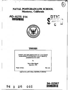
IV. IMPLEMENTATION In this paper an interactive user interface program is developed to extract STEP - Geometry data from neutral format STEP file using VB language as shown in Figure 1. EXPRESS Schema entity definitions for Geometry data are stored in MS Access (as database in this paper) and these are used in backend for validation. The Geometry data as vertex point, Cartesian point and axis-placement information etc, used in model design, information are extracted from STEP file as per the Express Schema entities in database. The extracted data is entered into the geometry database. A. Implementation procedure Step1: Choose the .stp file and save it in variable STEPFILE Step2: Open the file STEPFILE in read mode Step3: Read a line from STEPFILE into variable STEPLINE Step4: If STEPLINE equals to null GOTO Step 8 Step5: Separate the entity, entitydata1,entitydata2,…., entitydatam from STEPLINE in following manner. i Read character by character from STEPLINE ii Extract the entity to variable ENTITY iii Extract the entity data to variable ENTITYDATA1 iv Extract the next entity data to variable ENTITYDATA2 v And So on extract next entity data to variable ENTITYDATAM until end of the STEPLINE Step 6: Search the EXPRESS entity database for ENTITY in column “entity”. Step 7: If found store the ENTITY along with the ENTITYDATA1, ENTITYDATA2, . ., ENTITYDATAM in the Database “Geometric entity Database”. Step8: Otherwise increment the counter in STEPFILE and GOTO Step 3 Step9: STOP
It separates Geometric data from STEP file
Input the STEP file which is generated by modeling package
STORE Geometric data in the DATABASE
Creates TEXT file which includes Geometric data
Figure 1. Translator for separate and store STEP-Geometric
Sample VB code for Separation of STEP-Geometric data is given here Private Sub cmd_step_open_Click() .. comdlg.Filter = "STEP|*.stp|All STEP Files|*.stp;*.step" comdlg.ShowOpen step_file_name = comdlg.FileName If step_file_name = vbokcalncel Then End End If i=0 Set step_open = step_file_open_sys.OpenTextFile(step_file_name, 1, False, False) STEP_Translator.Refresh Do While step_open.AtEndOfStream = False step_file_data_line = Trim$(step_open.ReadLine) b=1 sEntityData$ = step_file_data_line sdata$ = RightOfChar(sEntityData$, "=") sEntityname$ = Trim$(LeftOfChar(sdata$, "(")) .. Loop Set step_open = Nothing k=0 step_file_data_line = "" Do While Not k = i step_file_data_line$ = step_dup.List(k) sEntityId$ = LeftOfChar(step_file_data_line$, "=") sEntityId$ = Replace(sEntityId$, "#", "_") If StrComp(sEntityId$, "") = 0 Then sEntityId$ = "_" + StrConv(k, vbLowerCase) End If Adodc1.Recordset.AddNew "id", Trim$(sEntityId$) sdata$ = RightOfChar(step_file_data_line$, "=") sEntityname$ = LTrim(LeftOfChar(sdata$, "(")) .. End If entity_data(j) = "entity_Data" + StrConv(j, vbLowerCase) Adodc1.Recordset.Update Array("id", "entity", entity_data(j)), Array(Trim$(sEntityId), Trim$(sEntityname$), Trim$(Replace(Replace(Replace(sdatainfo$, "#", "_"), "(", ""), ")", ""))) Loop If Not StrComp(Trim$(entity_data(j)), "") = 0 Then .. End If End If k=k+1 Loop End Sub
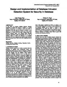
Figure 2. 3D Modeling of shaft used in under feeder
Figure 3. Assembly of under feeder
Sample STEP file for shaft model is given here ISO-10303-21; HEADER; FILE_DESCRIPTION(('CATIA V5 STEP Exchange'),'1'); FILE_NAME('F:\\shaft.stp','2000-12-31T18:41:08+00:00',('none'),('none'),'CATIA Version 5 Release 4 (IN-4)','CATIA V5 STEP AP203',' none'); FILE_SCHEMA(('CONFIG_CONTROL_DESIGN')); ENDSEC; DATA; #4=PRODUCT('Part',' ',' ',(#2)) ; #1=APPLICATION_CONTEXT('configuration controlled 3D design of mechanical parts and assemblies') ; #14=PRODUCT_DEFINITION(' ',' ',#5,#3) ; #16=SECURITY_CLASSIFICATION(' ',' ',#15) ; #15=SECURITY_CLASSIFICATION_LEVEL('unclassified') ; #49=CARTESIAN_POINT(' ',(0.000000000000,0.000000000000,0.000000000000)) ; ... 22098.0000000,1117.07079741)) ; #69=CARTESIAN_POINT('Control Point',(1618.10795774,-22098.0000000,1280.93729392)) ; #70=CARTESIAN_POINT('Control Point',(1487.44582125,-22098.0000000,1430.61766060)) ; ... #533=CARTESIAN_POINT('Control Point',(2324.10000000,18669.0000000,292.055522785)) ; #430=ORIENTED_EDGE('Oriented Edge',$,$,#401,.F.) ; ... #894=EDGE_CURVE('Edge Curve',#891,#893,#814,.T.) ; #959=EDGE_CURVE('Edge Curve',#893,#891,#895,.T.) ; #985=EDGE_CURVE('Edge Curve',#893,#984,#970,.T.) ; .. #48=(GEOMETRIC_REPRESENTATION_CONTEXT(3)GLOBAL_UNCERTAINTY_ASSIG NED_CONTEXT((#47))GLOBAL_UNIT_ASSIGNED_CONTEXT((#42,#43,#46))REPRESEN TATION_CONTEXT(' ',' ')) ; ENDSEC; END-ISO-10303-21;
In this paper, the model of shaft is created using CATIA V5 R16, as shown in Figure 2. A shaft used in under feeder consider for testing the interface program. The final assembly of crushing unit is shown in Figure 3.
After Separation of Geometric data from above STEP file by using Translator we get the following geometric data.
288
#133=CARTESIAN_POINT('Control Point',(-960.249188584,-22098.0000000,-1826.76869958)) ; #134=CARTESIAN_POINT('Control Point',(-840.938585266,-22098.0000000,-1884.67097418)) ; #135=CARTESIAN_POINT('Control Point',(-655.778535140,-22098.0000000,-1956.79143470)) ; …… #831=CARTESIAN_POINT('Control Point',(-3002.80476652,16764.0000000,-2982.63070619)) ; #832=CARTESIAN_POINT('Control Point',(-2854.19475913,16764.0000000,-3121.82126292)) ; ……. #1109=CARTESIAN_POINT('Control Point',(-2186.45783578,18669.0000000,-866.554242825)) ; #1110=CARTESIAN_POINT('Control Point',(-2278.22824516,18669.0000000,-584.110092083)) ; ……. #1014=ORIENTED_EDGE('Oriented Edge',$,$,#959,.F.) ; #1015=ORIENTED_EDGE('Oriented Edge',$,$,#985,.T.) ; #1016=ORIENTED_EDGE('Oriented Edge',$,$,#1007,.T.) ; ………. #190=EDGE_CURVE('Edge Curve',#113,#189,#187,.F.) ; #212=EDGE_CURVE('Edge Curve',#211,#189,#191,.F.) ; #220=EDGE_CURVE('Edge Curve',#111,#211,#213,.F.) ; …….. #1310=FACE_OUTER_BOUND('Face Bound',#1305,.T.) ; #1342=FACE_OUTER_BOUND('Face Bound',#1337,.T.) ; #1352=FACE_OUTER_BOUND('Face Bound',#1349,.T.) ; …… #440=TOROIDAL_SURFACE('homeo Torus',#439,4229.10000000,1905.00000000) ; #495=TOROIDAL_SURFACE('homeo Torus',#494,4229.10000000,1905.00000000) ; ……. #1273=VERTEX_POINT('Vertex Point',#1272) ; #1295=VERTEX_POINT('Vertex Point',#1294) ;
A. Future work More complete mechanism need to be developed for the modern prototype systems, thereby addressing complicated issues caused by viewing, and distributing of 3D models at any place. Instead of transferring the models in VRML format in internet explorer, if models can be transferred in the XML, and further to 3D XML, these models can be seen in internet explorer itself. ACKNOWLEDGMENT This work is partially supported by Department of Science and Technology, Government of INDIA, Technology Bhavan, New Delhi-110016, No.SR/S3/MERC81/06-SERC Engg. Dated 6 th March, 2007 REFERENCES [1]
Data Base have no information before separate the GEOMETRIC data from STEP file as shown in Table IV. TABLE IV. id
entity
entity_data0
[2]
GEOMETRIC ENTITY DATABASE …..
entity_data1
[3]
entity_datam
[4]
After completion of separation process above empty database filled with geometric data as shown in Table V. This information is useful for further processing. TABLE V.
DATA IN THE GEOMETRIC ENTITY DATABASE
id
entity
entity_data0
entity_data1
133
CARTESIAN _POINT
'Control Point'
831
CARTESIAN _POINT
'Control Point'
-960.249188584,22098.0000000,1826.76869958 3002.80476652,1676 4.0000000,2982.63070619
ORIENTED_ EDGE ORIENTED_ EDGE
'Oriented Edge'
$,$,#959,.F
'Oriented Edge'
$,$,#985,.T
EDGE_CUR VE EDGE_CUR VE
'Edge Curve'
#113,#189,#187,.F
'Edge Curve'
#211,#189,#191,.F
FACE_OUT ER_BOUND FACE_OUT ER_BOUND
'Face Bound'
#1305,.T
'Face Bound'
#1337,.T
TOROIDAL_ SURFACE
'homeo Torus'
#439,4229.10000000 ,1905.00000000
… 101 4 101 5 … 190 212 … 131 0 134 2 …. 440
[5]
…
[6]
entity_ data m
[7]
[8]
[9]
[10]
[11]
[12]
…
[13]
V.
CONCLUSIONS AND FUTURE WORK
In this paper concentrates on the extraction, storage and management of STEP-Geometric data from STEP file using EXPRESS schema entities are in the backend. This implementation provides flexible environment to the users, who are using STEP Geometry and manage the EXPRESS entity data. And also provide GUI which is easily understand by the even normal user. This tool useful to computer aided design and analysis industry, especially in downstream applications.
[14]
[15]
[16]
289
Loffredo, David, “Efficient Database Implementation of EXPRESS Information Models”. PhD Thesis, Rensselaer Polytechnic Institute, Troy, New York, May 1998. Schenck, D. and Wilson, P., “Information modeling: the EXPRESS way” Oxford University press, ISBN 0-19-508714-3,1994. ShahJ.J.,Rogers,M.T. and Urban,S.D. Engineering data management: achieving integration through database technology, Computing and Control Engineering Journal, 1993, pp. 9-26. Z. M. Ma, “Databases Modeling of Engineering Information” Northeastern University, China,2005. Mannisto, T., Peltonen, Soininen, & Sulonen. “Multiple abstraction levels in modeling product structures”. Date and Knowledge Engineering,36(1),2001, pp. 55-78. Shaw, N. K., Bloor, M. S., & de Pennington, A. “Product data models”. Research in Engineering Design, 1, 1989, pp. 43-50. Zhang, W. J., & Li, Q. “Information modeling for made-to-order virtual enterprise manufacturing systems”. Computer-Aided Design, 31(10),1999, pp. 611-619. Chen, G. Q., & Kerre, E. E.. “Extending ER/EER concepts towards fuzzy conceptual data modeling”. In Proceedings of the 1998 IEEE International Conference on Fuzzy Systems, Alaska,vol. 2,1998, pp. 1320-1325. Ahmed, S. “Classification standard in large process plants for integration with robust database”. Industrial Management & Data Systems, 104(8), 2004,pp. 667-673. Arnalte, S., & Scala, R. M. “An information system for computer integrated manufacturing systems”. Robotics and ComputerIntegrated Manufacturing, 13(3), 1997, pp. 217-228. Goh, A., et al. “A STEP/EXPRESS to object-oriented databases translator”. International Journal of Computer Applications in Technology,10 (1-2), 1997, pp. 90-96. Zhang, Q. Y. “Object-oriented database systems in manufacturing: selection and applications”. Industrial Management & Data Systems,101 (3), 2001, pp. 97-105. Ma, Z. M., et al. “Conceptual data models for engineering information modeling and formal transformation of EER and EXPRESS-G”. Lecture Notes in Computer Science, Vol. 2813,2003, pp. 573-575. Nadjib Bouikni, Louis Rivest and Alain Desrochers, “A Multiple Views Management System for Concurrent Engineering and PLM”, Concurrent Engineering, Vol. 16, No. 1,2008, pp. 73-87. M. Hardwick and D. Loffredo, “Using EXPRESS to Implement Concurrent Engineering Databases,” Proc. of the Ninth Annual ASME Engineering Database Symposium, Boston, Mass., September 17-21, 1995. http://www.nist.gov