National Astronomical Observatory of Japan, 2-21-1, Osawa, Mitaka, Tokyo, 181-8566, Japan. ABSTRACT .... decomposition of incident wave-front. The second ...
Implementation of modal optimization system of Subaru-188 adaptive optics Masayuki Hattori*a, Taras Golotaa, Guyon Oliviera, Matthew Dinkinsa, Shin Oyaa, Stephen Colleya, Michael Eldreda, Makoto Watanabea, Meguru Itoha, Yoshihiko Saitoa, Yutaka Hayanoa,b, Hideki Takamia,b, Masanori Iyeb a
Subaru Telescope (NAOJ), 650 North A’ohoku Place, Hilo, Hawaii, 96720, USA ; National Astronomical Observatory of Japan, 2-21-1, Osawa, Mitaka, Tokyo, 181-8566, Japan
b
ABSTRACT Subaru AO-188 is a curvature adaptive optics system with 188 elements. It has been developed by NAOJ (National Astronomical Observatory of Japan) in recent years, as the up grade from the existing 36-element AO system currently in operation at Subaru telescope. In this upgrade, the control scheme is also changed from zonal control to modal control. This paper presents development and implementation of the modal optimization system for this new AO-188. Also, we will introduce some special features and attempt in our implementation, such as consideration of resonance of deformable mirror at the lower order modes, and extension of the scheme for the optimization of the magnitude of membrane mirror in wave front sensor. Those are simple but shall be useful enhancement for the better performance to the conservative configuration with conventional modal control, and possibly useful in other extended operation modes or control schemes recently in research and development as well. Keywords: Adaptive Optics, Modal control, Optimization, Curvature Adaptive Optics
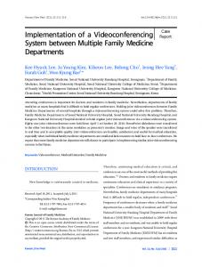
1. INTRODUCTION Adaptive optics is a system by which dynamically compensate the aberration on optical wave fronts and improves the quality of the convergence of the rays onto the image plane. As for recent astronomical telescopes with large diameter on the ground, use of adaptive optics to get rid of the degradation by the atmosphere, is essential to archive the good resolution expected by their large aperture size over the scale of the air turbulence. Subaru telescope, a one of such recent 'very large' telescope, located on the top of the Mauna-kea in Hawaii Island, actually utilize adaptive optics, as one of its enhanced feature, to archive a high resolution in infra-red imaging and spectroscopy. That first generation adaptive optics for Subaru telescope has 36-elements (we often call it 'Subaru AO-36') , and designed with the basis of curvature sensing and controlled by rather simple zonal method. Until now, we have been planning and constructing next generation AO system for Subaru Telescope, as the enhanced successor of this AO-36, based on the curvature system with bimorph mirror, but the number of the elements is increased up to 188 (it is often called Subaru AO-188), aiming the improved performance much closer to the resolution limit of the telescope itself. As the number of the elements in the adaptive optics increases, the control scheme of the real-time loop should be also improved in order to obtain the best performance of its ability, at the site of the actual observation. For Subaru AO-188, we are planning to develop and utilize the automated modal control scheme to achieve the best performance at anytime, which adapts the system's band-width to the change of air turbulence on time. For this purpose of the optimization of control system, a kind of control schemes often called 'modal optimization' is well known, and variation of similar methods can be seen in the textbooks[1] and papers[2-5], In this article, we are going to present our implementation of the modal optimization scheme in Subaru AO-188 on Subaru Telescope. Basically, our implementation is based on the modal control scheme, and optimization is done for the each modal servo gain. Fig.1 shows the location of such optimization scheme in the system of Subaru AO-188. The optimization function will be implemented on a computer called DHS that analyses amount of data coming from the real time control system. Advances in Adaptive Optics II, edited by Brent L. Ellerbroek, Domenico Bonaccini Calia, Proc. of SPIE Vol. 6272, 62725G, (2006) · 0277-786X/06/$15 · doi: 10.1117/12.671027
Proc. of SPIE Vol. 6272 62725G-1
.
Atmospheric Turbulance
Data Handling System (DHS) Computer
BS
Optimization routine • Data logging • Statistic query
Deform -able mirror
•
Auto commands APD/DM logs
DAC
Wave front sensor
To the Instruments
Wave front distortion
To the Telescope
Real Time Sytem Co mputer (RTS)
Fig. 1 The location of the optimization system in adaptive optics
Actually, we have already developed prototype of such optimization algorithm. To develop and test this optimization routine, we have appended data logging function to the AO-36 and captured data from APD and DM in the real observation. By using that data, we confirmed that the optimization scheme is basically applicable in our configuration of system. In this optimization algorithm, several advanced features are planned to be implemented, as well as the conventional functions of the modal servo optimization control. Among those extended functions, there are rather simple but possibly very useful ones; one is the optimization of magnitude of stroke of membrane mirror in curvature wave front sensor, another is the use of higher order response function in the temporal frequency analysis, and also is the statistic processing in estimation of modal power spectrum, etc. These extensions are aiming the complement of the basic scheme of the modal optimization, and make the system fully automatic, or extend the range of the optimization up to higher servo gains especially when the guide star is bright, i.e., the photon noise become less problem but the temporal response of the system may deviates from simple servo loop and become more serious problem, or may be attempt to keep the accuracy of the estimation of input power spectrum when the guide star is very dark and the signals are very noisy.
2. MODAL OPTIMIZATION METHOD Modal control is well known as a basic scheme for controlling the real time servo process in the closed loop of adaptive optics. The adaptive optics, which aiming to compensate the error of optical path distributed over the pupil plane, should be necessarily a multi-dimensional vector system by its nature. There have always been a lot of arguments when control of such multi-dimensional systems is considered. One may want to control adaptive optics more accurate, without losing the flexibility and robustness to the external conditions, while the capacity of the controller may be in any way limited; however fast the control computers may become, we still want to control the system in a faster cycle as possible in order to reduce the system's error from the temporal retardation. Modal control method is very popular one in recent adaptive optics. This is a range of control methods, in which, the real-time control loop of the adaptive optics is regarded as a servo loop up on a vector space; those vectors are related to the set of signals from wave-front sensor (WFS) and signals to the deformable mirror (DM) or more general types of wave front manipulators. The control rule is often described as a matrix multiplication from the signal of WFS to the control signal sent to DM. This control matrix C, is often used in a form of orthogonal decomposition as a pseudo-inverse form the response matrix, using such algorithm as SVD.
Proc. of SPIE Vol. 6272 62725G-2
∆ dm = C wfs = U S V wfs ∆t
(1)
where, dm and wfs describe the vector of signals in DM and WFS, and ∆ means a fraction for a single step of control. U, V represents a pair of orthogonal matrix, and the servo gain should be the multipliers to the elements of the diagonal matrix S, and its optimization is main concern in this paper. This simple modal decomposition control scheme is sometimes said to be too simple. Actually, it should be a case if the DM or WFS has nonlinearity, and this simple modal decomposition may be suffered from crosstalk among decomposed vector spaces. In spite of such possible problems, a good feature of the modal optimization is it provides a freedom to adapt the system's response to the operating condition with a very little increase of calculation in the real-time control loop, as far as the control matrix can be pre-configured before control loop is activated. This freedom of adjustment is usually used to adapt the system’s response to the condition of the turbulence of atmosphere, whose major characteristic is known to obey Kolgomorov's low. Or possibly, applied to some other phenomena that may be a major concern to the system's performance in particular cases. Another good point of this modal optimization is, that with use of the modal optimization, multi-dimensional vector feed back system can be decomposed into a very simple closed loop with the single scalar element, and the optimum loop gain of each of such simple servo loops can be estimated by a deterministic calculation [1-3] , as the optimum balance of total amount of the errors comes from the photon noise on the wave front sensor, and net amount of residual error that comes from the temporal response of the servo operation. The most simply, according Ref.1, this can be described in the mathematical form for each control mode. 2
σ
2
res
=∫
cntrl _ freq
0
2
cntrl _ freq 1 1 2 2 ε ( f ) df + ∫ N ( f ) df 0 1 + G( f ) W ( f ){1 + G ( f )}
(2)
Here, G is the circular (open-loop) transfer function and W is transfer function of the wave front sensor. And the two terms of the right hand side correspond to the residual error ε , and error from photon noise N.
Proc. of SPIE Vol. 6272 62725G-3
3. THE IMPLEMENTATION OF OPTIMIZATION SCHEME ON SUBARU AO SYSTEM The basic implementation of optimization routine is done as the schematic diagram in Fig.2. In general, the entire sequence of algorithms is divided into two parts. Fist part is the estimation of the temporal power spectrum of modal decomposition of incident wave-front. The second part is the least error search algorithm for servo gain among the possible range of their settings. In our implementation, the modal decomposition matrix is externally provided in relation to the one used in main control loop, and the optimization routine works separately but in accordance with real time control loop. This principle of implementation gives flexibility to test the various kind of modal decomposition and find its best parameters promptly.
Temporal Power- spectrum Analysis Accumulate APD/DM data Estimate temporal power spectrum of incident wave front Minimum error search for best setting Estimate wave front error at various setting of servo gain Search for the best servo gain and set one in the real time control loop Fig.2 Schematic diagram of the servo gain optimization routine for Subaru Adaptive optics
The next fig.3 is the schematic diagram of algorithm in more detail. This detailed diagram may look somewhat complicated. One may notice not only that the implementation of photon noise estimation have a separate branch in the algorithm, but also, rooms for the extensions of the algorithm are embedded already in its design. Actually, for the extension of the optimization of the stroke of membrane mirror in wave front sensor, the optimum search algorithm is slightly more complicated than a simple minimum search. This part of best search algorithm is designed to be capable of zonal optimization in order to do a test with AO-36. Also, statistic routine can be placed after the estimation of input power spectrum. This feature is expected to improve the performance with dark stars, since the photon noise may become intense as the guide star become dark, and statistic method may be useful to enhance the system’s stability and accuracy. These items made the actual implementation slightly more complicated than the original concept of modal optimization seen in the text book. The response function of AO control loop can be configured including second order harmonic terms
Proc. of SPIE Vol. 6272 62725G-4
Set APD/DM data on input buffer by function call Irradiance/Curvature decomposition
Input Buffer
Modal decomposition
curvature
Photon noise Estimation
i rradiance
Calculate modal Noize transfer Modal noise level
Multiply sytem constant fot the estimation of photn noise level
Statistic processing (optional) Modal tublance spectrum
Estimate modal error for the range of servo gains and membrane magnitude modal
Best search for each mode
FFT analysis to recover the spectum of signals on loop (with noise)
zonal
Sum up modal errors for each possible stroke magnitude of menbrane
Subtract photon noise to extract portion of input spectrum Input estimation Optimum search Best search with average of all modal errors
Best search Optimum modal servo gains
Optimum stroke of membrane
best searcdh among possible magnitude of membrane Optimum zonal servo gain
Output function call to AO main system Fig. 3 Detailed diagram of the configuration of the optimization routine.
The computer source code is written with C language, and is done so that is can be commonly used between AO-36 and AO-188. The intention of this feature is that testing of this optimization routine can be done with AO-36 under realistic condition of observation, before the AO-188 currently in development comes up. In this paper, the results of those tests with AO-36 will be shown in the next section. 4.
Proc. of SPIE Vol. 6272 62725G-5
4. TESING BASIC FUNCTIONS OF OPTIMIZATION ROUTINE WITH SUBARU AO-36 In this section, several results of testing of optimization routine with AO-36 will be shown. AO-36 is currently in operation at Subaru telescope, and test of the optimization routine are done with the data obtained under realistic condition with natural guide star and natural seeing. The data are stored to the files and test is done offline with reading those files. But, these results are still very meaningful, since the basic characteristics of the optimization routine can be tested before the new AO-188 comes up; the testing of optimization routine needs an AO system being already tuned up and working in good shape, while this might not be always a case as far as the AO-188 is still on the way of development. Fig.4 is an example of the result of the estimation of the temporal power spectrum of the input wave front. The modal decomposition matrix used with this test is one simply inverted from response matrix by singular-value decomposition algorithm, and in which, a term identical to the defocus was included at mode number 34. (Here, the mode numbers with nonzero singular value was in the order as m=0, 1, … 33, 34.) The result shows that the calibration of the transfer functions looks done well, and as a result, the solid line shows a cut-off characteristic to the noise floor cased by the photon noise in wave front sensor. The noise level, estimated from the photon number and its modal transfer, shows a good coincidence in the high-frequency end.
Sp,um R.sonst .34(Sfoais)
le+ll
Reconstucted Input turbulence DMirror signal WFSensor signal Photon Nois
le+lO
—
-
I
le+09 N
N
le+08
I
= E
1;
le+07
100000
10000
10
100
1000
Fiequency [Hz]
Fig.4 Reconstruction of the temporal power spectrum of the input wave front. The graph is the result for the defocus mode. The estimation of the photon noise level (straight dotted line) shows a good coincidence with the high frequency region of the signal from wave front sensor and that of the reconstructed power spectrum.
Next, Fig.5 shows the result of error estimation and minimum error search. Since the AO-36 use simple zonal control with one common servo gain, we tried to test if such single total gain can be estimated by best search with the average of error of all the modes. The relation between such zonal error and modal errors would be more complicated than a simple average, and the covariance between the modes should be taken into account. But at this time, simple average of the errors is used for the testing purpose as the beginning. For the reference, the best the servo gain at that time by the experimental estimation was 0.11, at which the Strehl ratio of the actual PSF on the imaging became the best. The
Proc. of SPIE Vol. 6272 62725G-6
estimation by the optimization routine was slightly smaller than that so far, but it seems that such deviation can be reduced by doing fine calibration, and the accuracy should be much improved from the result shown here..
Gain Estim totSzonal :svg :0.1208 Best gain estimation, / defocus
ResE,, Defocu-
le+09
ResE,,Totvs svg best
0
C
+
Estimated Op joS (wavefrontI Error [Relatiw
/
le+07
I
I
0.01
al Servo GSn
Fig.5 The result of minimum error search. The plots with square are the average of the residual error on all the modes. The averaging procedure was necessary because Subaru AO-36 has simple zonal control with single servo gain. At the test observation, the best servo-gain was found around 0.11 experimentally, and that was slightly larger than the estimation by the optimization algorithm (plotted by x on the graph.) The dotted line is a single-mode error curve for the defocus mode. The error curvature of such single mode also looks stable enough to do the minimum search.
The calculation speed of the basic estimation routine was more than 100 modes par seconds, by using a computer with Pentium4 2.4GHz. when the integration time length of the temporal power spectrum was 8.2 sec while the operation cycle of the closed loop was at 2000Hz. At this speed, all the control modes on 188-elemts adaptive optics can be calculated within 2 seconds, and it will provide enough speed to do the optimization of the stroke of membrane mirror in the wave front sensor.
5. EXTENTIONS OF THE OPTIMIZATION ROUTINE In this section, the extensions of the optimization routine and their current status are summarized. 5.1 Optimization of vibration on membrane mirror in curvature wavefront sensor The magnitude of stroke of membrane mirror changes sensitivity of the curvature wave front sensor. But, it should be noted that, this change of the sensitivity does not only changes the servo gain, but more importantly, changes the signal to noise ratio between the curvature signal and the photon noise. At this point of view, the change of the membrane
Proc. of SPIE Vol. 6272 62725G-7
stroke is essentially different from a simple multiplier imposed on the control computer, which we usually call as ‘servo gain.’ Another special point of changing the membrane stroke is that the change of this only one variable has effect to every the control mode. Also, this increase of the sensitivity may saturate, or may even decrease, for the spatially high frequency modes. Since, increase of membrane mirror generally improves the sensitivity to the wave front curvature but also reduces spatial resolution. Thinking of those factors, search of the optimum magnitude of membrane stroke is somewhat complicated, but still should be able to be done as an extension of the optimization algorithm. Our optimization routine have already been designed and implemented to be capable of this feature. For this purpose, the minimum error search algorithm has extra looping, and can incorporate estimation of wave front error at variation of magnitude of membrane stroke. To make this function useful, calibration with realistic value should be necessary. We are also planning tests of this feature by numerical simulator, since most of phenomena arise from the change of the membrane stroke as above, can be well reproduced by the numerical simulation. 5.2 Use of higher order response function in estimation of temporal signal power spectrum As for AO-36, the weak resonance of deformable mirror is sometimes seen when the servo gain is set high. Although the resonance are well controlled and intense resonance is well suppressed, so it may not do any harm on the optical parts, but still very weak resonance may deviates the system’s response from simple servo loop. It can possibly be one limit to the performance with a bright reference starts. As a simplest method to avoid this effect, we are planning to incorporate the higher order response function including up to harmonic resonance. The more than 2000Hz of time resolution in the Subaru AO is sufficient to capture the resonance frequency of deformable mirror. As for this feature, the harmonic resonance is already incorporated in the response function in the optimization routine. But, still more studies are necessary; such method can be really effective with some kind of modal decomposition matrix. Also, accurate calibrations will be necessary for realistic test and practical use. 5.3 Statistic calculation in estimation of input power spectrums The estimation of the power spectrum of input wave front contains a lot of noise especially in the high frequency region, as is seen in the Fig.4. That is because the photon noise is dominant in those regions of the signals from the wave front sensor. But, it is known that, the turbulence of the air obeys the power low of Kolmogorov. Therefore, the Fourier coefficient of the modal signal can be mathematically calculated; that means there should be a good method to estimate the input spectrum by function fitting, while possible problem in doing so would be a amount of numerical calculation to do so. We are currently investigating the best method with our case, with using the results obtained from AO-36. 5.4 Other extensions The optimum search algorithm in optimization routine is currently written with the basis of direct search of best error with second order interpolation as is shown in Fig.4. Fortunately, this seems enough accurate and speedy, and gives good perspective to the operators; about what setting may cause how much error. But of cause, we may replace that error search method with other differential search schemes for further improvement of speed. [5] Another extension comes from the discussion about the spatial resolution of wave front sensor in the section 5.1, and it will comes to another idea, optimization with the extended reference source; such sources with finite extent may reduce the essential sensitivity in high spatial frequency by the image blur in the wave front sensor, as well as a large stroke of membrane does. This extension will be useful for the use of extended object as a guide star, and also may be useful with a laser guide star, that has a finite spatial extent by its nature. .
6. SUMMARY The implementation and first tests results of the optimization system for the modal closed loop control in the 188 element next generation adaptive optics for Subaru Telescope (Subaru AO-188) is shown. The basic function for the estimation of the best servo gain was achieved in the fist test. That was done with actual observation data with current 36-element Subaru AO system (Subaru AO-36). Also, the plans of extensions and their current status are introduced. The source code of optimization routine is so written that those extensions may be done efficiently. We are continuing the efforts to complete the system. The precise calibration of the system and more detailed investigation of the system’s performance are yet to be done. For example, robustness for the dark guide star should be one of the important items to be confirmed.
Proc. of SPIE Vol. 6272 62725G-8
REFERENCES 1. F. Roddier Ed., “Adaptive Optics in Astronomy”, Cambridge University Press, (1999) 2. E. Gendron and P. Lena, “Astronomical adaptive optics: I. Modal control optimization”, Astron. Astrophys. 337347 (1995) 3. E. Gendron and P. Lena, “Astronomical adaptive optics: II. Experimental results of an optimized modal control”, Astron. Astrophys. Suppl. Ser. 111, 153-167 (1995) 4. B. L. Ellerbroek, C. Van Loan, N. P. Pitsianis, R. J. Plemmmons, “Optimizing closed-loop adaptive-optics performance with use of multiple control banwidths”, J.Opt.Soc.Am. A 11(11), 2871-2786 (1994) 5. M. J. Smith and J.P.Veran, “Implementation of the Altair optimization processes”, Proc SPIE vol.4839. 964-971 (2003)
Proc. of SPIE Vol. 6272 62725G-9