Fernuniversität Hagen. D-58084 Hagen. GERMANY thomas.deridder@fernuni-
hagen.de. Markus Schneider. Praktische Informatik IV. Fernuniversität Hagen.
Implementation of the ROSE Algebra: Efficient Algorithms for Realm-Based Spatial Data Types
Ralf Hartmut Güting
Thomas de Ridder
Markus Schneider
Praktische Informatik IV Fernuniversität Hagen D-58084 Hagen GERMANY
[email protected]
Praktische Informatik III Fernuniversität Hagen D-58084 Hagen GERMANY
[email protected]
Praktische Informatik IV Fernuniversität Hagen D-58084 Hagen GERMANY
[email protected]
Abstract: The ROSE algebra, defined earlier, is a system of spatial data types for use in spatial database systems. It offers data types to represent points, lines, and regions in the plane together with a comprehensive set of operations; semantics of types and operations have been formally defined. Values of these data types have a quite general structure, e.g. an object of type regions may consist of several polygons with holes. All ROSE objects are realm-based which means all points and vertices of objects lie on an integer grid and no two distinct line segments of any two objects intersect in their interior. In this paper we describe the implementation of the ROSE algebra, providing data structures for the types and new realm-based geometric algorithms for the operations. The main techniques used are (parallel) traversal of objects, plane-sweep, and graph algorithms. All algorithms are analyzed with respect to their worst case time and space requirements. Due to the realm properties, these algorithms are relatively simple, efficient, and numerically completely robust. All data structures and algorithms have indeed been implemented in the ROSE system; the Modula-2 source code is freely available from the authors for study or use. Keywords: Spatial data types, algebra, realm, finite resolution, numerical robustness, efficient algorithms, plane sweep, ROSE.
This work was supported by the DFG (Deutsche Forschungsgemeinschaft) under grant Gu 293/1-2.
−
1
−
1 Introduction We consider a spatial database system to be a full-fledged database system with additional capabilities for representing, querying, and manipulating geometric data (for a survey see [Gü94]). Such a system provides the underlying database technology needed to support applications such as geographic information systems and others. Spatial data types like point, line, and region provide a fundamental abstraction for modeling the structure of geometric entities, their relationships, properties, and operations. Their definition and implementation is probably the most fundamental issue in the development of spatial database systems. There have been quite a few proposals for systems of spatial data types and operations, or spatial algebras; they have been embedded into query languages, implemented in prototype systems, and some of them have been defined formally. For a discussion and references see [GüS93b, Gü94]. This paper continues the development of one such proposal, the ROSE algebra [GüS93b], which has a number of interesting features: (i) it offers (values of) data types of a very general structure, (ii) has a complete formal definition of the semantics of types and operations, (iii) has a discrete geometric basis (socalled realms, see below) which allows for a correct and robust implementation in terms of integer arithmetics, (iv) treats consistency between distinct geometric objects with common parts, and (v) has a general object model interface which allows it to cooperate with different kinds of database systems. The development of the ROSE algebra so far consists of three steps: (1) the concept of a realm [GüS93a] as a discrete geometric basis, (2) the formal definition of the ROSE algebra itself offering realm-based spatial data types and operations [GüS93b], and (3) the ROSE system as an implementation of the ROSE algebra, which realizes its types and operations by providing efficient data structures and algorithms defined over a discrete grid. This third step is the subject of this paper. Let us briefly review the first two steps. A realm conceptually describes the complete underlying geometry of a particular application space in two dimensions. Formally, a realm is a finite set of points and line segments over a discrete grid (see Figure 1(a)) such that (i) each point and each end point of a line segment is a grid point, (ii) each end point of a realm segment is also a point of the realm, (iii) no realm point lies within a realm segment (which means on it without being an end point), and (iv) no two realm segments intersect except at their end points. The idea is now to construct the geometries of spatial objects by composing them from realm primitives (see Figure 1(b)). The realm concept solves numerical robustness and topological correctness problems, enforces geometric consistency of related spatial objects, and enables one to formally define spatial data types or algebras on top of it that enjoy nice closure properties not only in theory but also in an implementation.
C A
B D
(a) Example of a realm
(b) Realm objects over the realm in (a) Figure 1
−
2
−
The ROSE algebra [GüS93b] offers three data types called points, lines, and regions whose values are realm-based, i.e. composed from elements of a realm, together with a comprehensive set of operations. Figure 2 illustrates these data types.
a points value
a lines value
a regions value
Figure 2: Examples of spatial values The structure of spatial objects is defined in terms of the notions of an R-point, an R-block and an R-face. For a given realm R, an R-point is a point of R. An R-block is a connected set of line segments of R. An R-face is essentially a polygon with holes that can be defined over realm segments. Then a value of type points is a set of R-points, a value of type lines is a set of disjoint R-blocks, and a value of type regions is a set of edge-disjoint R-faces (where edge-disjoint means that two faces may have a common vertex, but no common edge). There are four classes of spatial operations: (1) spatial predicates expressing topological relationships (e.g. inside, intersects, meets), (2) operations returning atomic spatial data type values (e.g. intersection, plus, minus, contour), (3) spatial operators returning numbers (e.g. dist, perimeter, area), and (4) spatial operations on sets of database objects (e.g. sum, closest, fusion). The signature of the first three groups of operations of the ROSE algebra can be found in the Appendix, for the meaning of operations see [GüS93b]. The operations of the fourth group have not yet been implemented because they require the implementation of the object model interface (described in [GüS93b]) which is not yet available. The topic of this paper is the implementation of the ROSE algebra. To be precise, we must distinguish between a descriptive and an executable algebra [Gü89, BeG92]. A descriptive algebra offers types and operations at a conceptual level which can be used to formulate queries; its semantics are given by defining a “carrier” set of objects for each sort of the algebra and a function for each operator. An executable algebra describes the actual representations and query processing algorithms present in a system; hence in such an algebra there is a data structure associated with each sort (or type) and an algorithm, or a procedure realizing it, with each operator. In a database system, it is the task of the optimizer to translate an expression of the descriptive algebra into an equivalent, efficiently evaluable expression of the executable algebra. The ROSE algebra, as defined in [GüS93b], is a descriptive algebra. Hence in this paper we first describe a corresponding executable algebra - essentially polymorphic descriptive operators are decomposed into several executable operators - and then data structures and algorithms to implement it. The main new aspects of this design and paper are the following: • We describe at a very high level, yet precisely, robust and efficient algorithms dealing with the complex geometric entities available in the ROSE algebra. They can be grouped into parallel traversal, plane sweep, and graph algorithms. For each paradigm, we show a few “prototype” operators and their algorithms and discuss which other operators can be realized similarly and which modifications are necessary. Many algorithms require only linear time, the remaining ones O(n log n) time where n is a bound on the size of the operand objects.
−
3
−
• All spatial objects processed by the operations are realm-based, i.e., they are defined over a discrete basis and in particular no two segments intersect within their interiors and no point lies within a segment. These properties can be exploited for designing efficient geometric algorithms. For example, many operations can now be realized through a simple parallel traversal for which otherwise more complex and expensive plane sweep algorithms would be needed. When plane sweep is needed, it is simpler because no intersection points of segments can be discovered during the sweep (e.g., a static sweep event structure can be used). • In contrast to traditional papers on algorithms, the focus is not on finding the most efficient algorithm for one single problem (operation), but rather on considering a spatial algebra as a whole, and on reconciling the various requirements posed by different algorithms within a single data structure for each type. We are not aware that implementations of complete spatial algebras have been described before in a similar manner. • The implementation is designed for use in a spatial database system. In particular, representations for spatial data types do not use pointer data structures in main memory, but are all embedded into compact storage areas which can be efficiently transferred between a main memory buffer and disk. Data structures are also designed to allow for realm updates. • The ROSE system has actually been implemented and is running; the complete source code is available from the authors for study or use [Ri95]. The implementation was done in Modula-2 for UNIX systems. We feel it is important to make such well-designed “modules” for spatial DBMS systems available to the research community. The importance of a finite-precision / finite-resolution computational geometry, as described in this paper, defined on a uniform, discrete grid such that points, end points of line segments, vertices of polygons etc. have integer coordinates instead of arbitrary floating-point coordinates, has been emphasized by Greene and Yao [GrY86] as well as Yao [Ya92]. Finite-precision geometry has so far only been studied by a few researchers (overviews can be found in [KeK81, Ov88b, Ov88c]). Problems considered are, for example, the nearest neighbour searching problem [KaM85], range searching on a grid [Ov88a, Ov88b], the point location problem [Mü85], the computation of rectangle intersections and maximal elements by divide-and-conquer [KaO88b], computing the convex hull of a set of points, reporting all intersections of a set of arbitrarily oriented line segments, and the calculation of rectangle intersections and maximal elements by using the plane-sweep technique [KaO88a, Ov88b]. To our knowledge, geometric algorithms over a discrete domain for more complex structures like those of the ROSE algebra have not been described in the literature. The paper is structured as follows: In Section 2 an executable algebra is designed for the given descriptive ROSE algebra. In Section 3 we give a high-level specification of data structures for the representation of ROSE objects which provides a basis for the subsequent description of algorithms. Section 4 introduces realm-based geometric algorithms for the implementation of ROSE operations. Section 5 shows the actual data structures used and discusses some important implementation concepts.
2
Descriptive and Executable ROSE Algebra
In this section we develop an executable algebra for the given descriptive ROSE algebra. Essentially this means that we have to decompose each polymorphic descriptive operator into corresponding executable operators for the possible combinations of data types. Both algebras use second-order signature [Gü93] as the underlying formalism. Second-order signature allows one to define a type system together with an algebra over that type system. In particular, it is possible to describe polymorphic
−
4
−
operations by quantification over kinds. For the purpose of this paper it suffices to view kinds just as type sets; the two relevant sets are EXT = {lines, regions} and GEO = {points, lines, regions}. Here are a few examples of spatial predicates of the ROSE algebra: ∀ geo in GEO. ∀ ext1, ext2 in EXT. ∀ area in regionsarea-disjoint. geo × geo → bool =, ≠, disjoint geo × regions → bool inside ext1 × ext2 → bool intersects area × area → bool adjacent, encloses Here geo is a type variable ranging over the three types in kind GEO so that the first three operations can compare two values of equal type and the inside operation can compare a points, a lines, or a regions value with a regions value. The intersects operation can be applied to two values of the same or different type within kind EXT. The notation regionsarea-disjoint is an attempt to capture the structure of partitions of the plane (into disjoint regions) in the type system. It ensures that the two operands given to the adjacent or encloses operator are two regions taken from the same partition of the plane, hence they are either disjoint or equal; for details see [GüS93b]. For the executable algebra this is not relevant and we can introduce executable operators with functionality regions × regions → bool. In the executable algebra, we generally need different algorithms for the different data types. For example, it is obvious that an algorithm which examines the disjointness of two points objects will be different from an algorithm which determines whether two regions objects overlap. Hence the descriptive operator disjoint is mapped to the three executable operators: points × points lines × lines regions × regions
→ bool → bool → bool
pp_disjoint ll_disjoint rr_disjoint
The Appendix lists the signature of the ROSE algebra and shows its translation into executable operators. For example, the first line of the ROSE signature shown above is represented as follows: Descriptive Operator geo × geo → bool
Executable Operator
PT
PS
G
TC
=
pp_equal, ll_equal, rr_equal
x
O(n)
≠
pp_unequal, ll_unequal, rr_unequal
x
O(n)
pp_disjoint, ll_disjoint
x
O(n)
disjoint
rr_disjoint
x
O(n log n)
The last four columns of this table describe the algorithmic technique used to implement this (group of) executable operators (PT = parallel traversal, PS = plane sweep, G = graph algorithm) and the worst case time complexity. The algorithms are discussed below. There is a gap in the table because we have not yet studied efficient algorithms for distance problems (operator dist of the third group).
3
Specification of Data Structures for the Types
Algorithms for the executable ROSE operators need to access, and sometimes to build, the data structures representing values of the three types points, lines, and regions. Rather than describing these data structures directly in terms of arrays, records, etc., we first introduce a higher level description
−
5
−
which offers suitable access and construction operations to be used in the algorithms. Basically, we define a little abstract data type for each of the three data structures. In a second step, one can then design and implement the data structure itself. The specification of an abstract data type consists of a many-sorted signature together with a set of laws, or equations, defining the behaviour of operations. To be precise, we use a slightly different specification method sometimes called “denotational specification” (e.g. [Kl83]). It simply means that we assign semantics to the sorts and operations of the many-sorted signature directly by defining carrier sets for the sorts and functions for the operations on these carrier sets, i.e., we define a little algebra for each of the three data structures representing points, lines, or regions values, respectively. In other words, we give a concrete mathematical model for the data type instead of a set of laws. In fact, the whole ROSE algebra itself has been defined by the same method. For most executable operators it turns out to be sufficient to regard a spatial object as an ordered sequence of elements where it is possible to access these elements consecutively and to insert a new element into the sequence. Hence this is our basic strategy for modeling the three data structures. Before we can introduce the algebra points, a few notations are needed. Realms and realm-based spatial objects are defined over a finite discrete space N × N with N = {0, ..., m − 1} ⊆ N. PN = {(x, y) | x ∈ N, y ∈ N} denotes the set of all N-points. Furthermore, an (x, y)-lexicographic order is assumed on PN which is defined as p1 < p2 ⇔ x1 < x2 ∨ (x1 = x2 ∧ y1 < y2). algebra points sorts
points, PN, bool
ops
new select_first select_next end_of_pt get_pt insert
sets
: : : : : :
points points points points points × PN
→ points → points → points → bool → PN → points
points = {(pos, < p1, ..., pn >) | pos ≥ 0; n ≥ 0; for 1 ≤ i ≤ n, pi ∈ PN; for 1 ≤ i < n, pi < pi+1}
functions Let P = (i, < p1, ..., pn >) ∈ points and p ∈ PN. new() = (0, ◊) (1, < p1, ..., pn >) if n ≥ 1 select_first(P) = (0, ◊) otherwise (i + 1, < p1, ..., pn >) if 1 ≤ i < n select_next(P) = (0, < p1, ..., pn >) otherwise end_of_pt(P) = (i = 0) pi if 1 ≤ i ≤ n get_pt(P) = undefined otherwise (j, < p1, ..., pn >) insert(P, p) = (1, < p, p1, ..., pn >) (n + 1, < p1, ..., pn, p>) (j + 1, < p1, ..., pj, p, pj+1, ..., pn >) end points.
if ∃ j ∈ {1, ..., n}: p = pj if p < p1 if p > pn if ∃ j∈{1, ..., n-1}: pj < p < pj+1
−
6
−
The sorts and ops parts describe the syntax of the algebra, i.e., the signature. The sets and functions parts give the semantics in terms of carrier set and function definitions. The algebra points contains the sorts points (to be defined), PN, and bool. The carrier set of the sort points is defined as the set of all ordered sequences < p1, ..., pn > of n N-points together with a pointer indicating a position within the sequence. The symbol ◊ denotes the empty sequence. Functions manipulate such values, for example, select_first positions the pointer pos on the smallest element of the point sequence, and get_pt yields the point at the current position. A crucial idea for the representation of the relatively complex lines and regions values, which is the basis for most of our algorithms, is to regard them as ordered sequences of halfsegments. Let SN = {(p, q) | p ∈ PN, q ∈ PN} denote the set of N-segments. The equality of two N-segments s1 = (p1, q1) and s2 = (p2, q2) is defined as s1 = s2 ⇔ (p1 = p2 ∧ q1 = q2) ∨ (p1 = q2 ∧ p2 = q1). W. l. o. g. we normalize SN by the assumption that ∀ s ∈ SN : s = (p, q) ⇒ p < q which enables us to speak of a left and a right end point of a segment. Let further HN = {(s, d) | s ∈ SN, d ∈ {left, right}} be the set of halfsegments. A halfsegment h = (s, d) consists of an N-segment s and a flag d emphasizing one of the Nsegment’s end points which is called the dominating point of h. If d = left then the left (smaller) end point of s is the dominating point of h, and h is called left halfsegment. Otherwise, the right end point of s is the dominating point of h, and h is called right halfsegment. Hence, each N-segment s is mapped to two halfsegments (s, left) and (s, right). Let dp be the function which yields the dominating point of a halfsegment. For two distinct halfsegments h1 and h2 with a common end point p, let α be the enclosed angle such that 0 < α ≤ 180° (an overlapping of h1 and h2 is excluded by the realm properties). Let a predicate rot be defined as follows: rot(h1, h2) is true iff h1 can be rotated around p through α to overlap h2 in counter-clockwise direction. We can now define a complete order on halfsegments which is basically the (x, y)-lexicographic order by dominating points. For two halfsegments h1 = (s1, d1) and h2 = (s2, d2) it is: h1 < h2 ⇔ dp(h1) < dp(h2) ∨ (dp(h1) = dp(h2) ∧ ((d1 = right ∧ d2 = left) ∨ (d1 = d2 ∧ rot(h1, h2)))) We now define the algebra regions (the algebra lines is almost the same, see below). The carrier set of the sort regions is defined as the set of ordered sequences < h1, ...., hn > of halfsegments where each halfsegment hi has an attached set of attributes ai whose elements are values of some new sort attr. Attribute sets are used in algorithms to attach auxiliary information to segments. algebra regions sorts
regions, HN, attr, bool
ops
new select_first select_next end_of_hs get_hs get_attr update_attr insert
: : : : : : : :
→ regions regions → regions regions → regions regions → bool regions → HN regions → attr regions × attr → regions regions × HN → regions
− sets
7
−
regions = {(pos, < h1, ..., hn >, < a1, ..., an >) | (1) pos ≥ 0, n ≥ 0 (2) ∀ i ∈ {1, ..., n} : hi ∈ HN, ai ⊆ attr (3) ∀ i ∈ {1, ..., n-1} : hi < hi+1 }
functions Let Rh = < h1, ..., hn >, Ra = < a1, ..., an >, R = (i, Rh, Ra) ∈ regions, and h ∈ HN. new() = (0, ◊, ◊) (1, Rh, Ra) if n ≥ 1 select_first(R) = (0, ◊, ◊) otherwise (i + 1, Rh, Ra) if 1 ≤ i < n select_next(R) = (0, Rh, Ra) otherwise end_of_hs(R) = (i = 0) hi if 1 ≤ i ≤ n get_hs(R) = undefined otherwise ai if 1 ≤ i ≤ n get_attr(R) = undefined otherwise (i, Rh, < a1, ..., ai-1, a, ai+1, ..., an >) if 1 ≤ i ≤ n update_attr(R, a) = undefined otherwise (j, Rh, Ra) if ∃ j ∈ {1, ..., n}: h = hj (1, < h, h1, ..., hn >, < ∅, a1, ..., an >) if h < h1 insert(R, h) = (n + 1, < h1, ..., hn, h>, < a1, ..., an, ∅>) if h > hn (j + 1, < h1, ..., hj, h, hj+1, ..., hn >, < a1, ..., aj, ∅, aj+1, ..., an >) if ∃ j ∈ {1, ..., n-1}: hj < h < hj+1 end regions. Note that the algebra regions just offers manipulation of halfsegment sequences; it does not ensure that a sequence indeed represents a correct regions value as defined in the ROSE algebra. The algorithms using this structure are responsible for constructing only sequences that indeed represent regions values. The algebra lines (not presented here) is identical to the algebra regions except for all the parts related to attributes which are not needed. Simple implementations for each of the three data types (algebras) would represent a sequence of n points or halfsegments in a linked list or sequentially in an array; the latter representation would also be compatible with the “compact storage area” requirement needed for efficient database loading/storing. In this case, all operations except for insert need O(1) time; insert requires O(n) time for arbitrary positions and O(1) time for appending an element at the end of the sequence. Such a representation would in fact be quite good for all “parallel traversal” algorithms of the ROSE algebra, because result objects are always constructed in the lexicographic point or halfsegment order and can therefore be built in linear time. The actual implementation in the ROSE system uses for all three structures an AVL-tree embedded into an array (the array serving as a storage pool for nodes); the elements, i.e. points or halfsegments, are additionally linked in sequence order. With this representation, all operations except insert need O(1) time and insert O(log n) time. The requirement to support insertion in O(log n) time actually does not come from the ROSE algebra but from the connection with realms; realm updates due to insertion of points or segments into the realm must be propagated to ROSE objects residing in a database [GüS93a]. This means that the data structures should support replacement of a segment in a lines or
−
8
−
regions object by a chain of segments, i.e., the segment must be deleted and the replacement segments be inserted into the structure. Unfortunately, a consequence of this is that the parallel traversal algorithms cannot construct the result objects in linear time any more, but need O(k log k) for this where k is the size of the result object. This is a case of conflicting requirements, as mentioned in the introduction. On the other hand, deriving the internal structure of a lines or regions object (e.g. faces and holes) which is needed to complete the construction (see Section 5) requires O(k log k) time anyway.
4
Algorithms for the Executable Algebra
This section introduces realm-based geometric algorithms whose characteristic features are numerical robustness, topological correctness, closure properties, and efficiency. Realm-based algorithms are more efficient than their Euclidean counterparts. The design of these algorithms is based on traversal techniques, on the plane-sweep paradigm, and on graph theory. Realm-based geometry deals with spatial objects that are defined over the same discrete domain and assumes that no two segments intersect within their interiors and that no point lies within a segment. Executable operators are grouped by the applied algorithmic technique. For each group we show and explain some example algorithms.
4.1 Algorithms with Simple or Parallel Object Traversal A number of operators of the executable ROSE algebra can be realized by a simple or parallel traversal (scan) through the point or halfsegment sequence of one or two objects. To simplify the description of algorithms, for each possible combination of two spatial data types two operations are introduced which allow for a parallel traversal through two ordered sequences of elements (halfsegments, points). As an example, we consider the two operations for two regions objects. The operation rr_select_first(R1, R2, object, status) selects the first halfsegment of each of the regions objects R1 and R2 (compare to the function select_first of algebra regions) and positions a logical pointer on both of them. The parameter object with possible values {none, first, second, both} indicates which of the two object representations contains the smaller halfsegment. If the value of object is none, no halfsegment is selected, since R1 and R2 are empty. If it is first (second), the smaller halfsegment belongs to R1 (R2). If it is both, the first halfsegments of R1 and R2 are identical. The parameter status with possible values {end_of_none, end_of_first, end_of_second, end_of_both} describes the state of both halfsegment sequences. If the value of status is end_of_none, both objects still have halfsegments. If it is end_of_first (end_of_second), R1 (R2) is empty. If it is end_of_both, both object representations are empty. The operation rr_select_next(R1, R2, object, status) searches for the next smaller halfsegment of R1 and R2; parameters have the same meaning as for rr_select_first. Obviously, this is realized by select_next operations of the two objects. Both operations together allow one to scan in linear time two object representations like one ordered sequence. Analogous operations can be defined for two lines objects (ll_select_first, ll_select_next) and a lines and a regions object (lr_select_first, lr_select_next). For the comparison of halfsegments with points, the dominating points of the halfsegments are used so that points and lines objects
−
9
−
(pl_select_first, pl_select_next) as well as points and regions objects (pr_select_first, pr_select_next) can be treated in a similar way. In the sequel we discuss algorithms for the operations (see algorithms below): points × regions points × points lines × lines
→ bool → points → bool
pr_on_border_of pp_plus ll_intersects
Operator pr_on_border_of determines whether all points of a points object lie on the faces’ boundaries of a regions object. Hence the algorithm checks whether for each point p of a points object P (denoted as p ∈ P(P)) a halfsegment h of a regions object R (denoted h ∈ H(R)) exists whose dominating point is equal to p. The while-loop of the algorithm is executed as long as no point is found which is in P but not a dominating point of a halfsegment of R and as long as none of the object sequences is exceeded. For the predicate to be true, termination of the while-loop must not have occurred because a point was found which is not on the boundary of R (object ≠ first). This implies that termination is due to reaching the end of one or both sequences, and the predicate is true if this was not the regions sequence alone (status ≠ end_of_second). Operator pp_plus forms the union of two points objects. The algorithm just scans the point sequences of the two objects and merges them into a new points object. algorithm pr_on_border_of input: A points object P and a regions object R output:true, if ∀ p ∈ P(P) ∃ h ∈ H(R) : p = dp(h) false, otherwise begin pr_select_first(P, R, object, status); while (object ≠ first) and (status = end_of_none) do pr_select_next(P, R, object, status); end-while; return (object ≠ first) and (status ≠ end_of_second) end pr_on_border_of.
algorithm pp_plus input: Two points objects P1 and P2 output:A points object Pnew containing all points begin Pnew := new(); pp_select_first(P1, P2, object, status); while status ≠ end_of_both do if object = first then p := get_pt(P1) else if object = second then p := get_pt(P2) else if object = both then p := get_pt(P1) end-if; Pnew := insert(Pnew, p); pp_select_next(P1, P2, object, status); end-while; return Pnew end pp_plus.
algorithm ll_intersects input: Two lines objects L1 and L2 output:true, if no common segment exists, but a common point which is not a meeting point false, otherwise begin ll_select_first(L1, L2, object, status); if object = first then act_dp := dp(get_hs(L1)) else if object = second then act_dp := dp(get_hs(L2)) end-if; act_obj := object; found := false; count := 0; while (status = end_of_none) and (object ≠ both) do ll_select_next(L1, L2, object, status); if (status ≠ end_of_both) and (object ≠ both) and not found then if object = first then new_dp := dp(get_hs(L1)) else if object = second then new_dp := dp(get_hs(L2)) end-if; if new_dp ≠ act_dp then (* new point *) act_dp := new_dp; count := 0; act_obj := object; else if object ≠ act_obj then (* object switch *) count := count + 1; act_obj := object; found := found or (count > 2); end-if; end-if; end-while; return found and (object ≠ both); end ll_intersects.
−
10
−
Operator ll_intersects examines whether two lines objects L1 and L2 intersect. According to the definition of the ROSE algebra it yields true if both objects have no common (half)segments but at least one common point which is not a meeting point but an intersection point. Point p is a meeting point if the angularly sorted list of halfsegments of L1 and L2 with the same dominating point p can be subdivided into two sublists so that one list contains only halfsegments of L1 and the other list only halfsegments of L2. The idea is now to walk around p, scanning the segments, and to count the number of “object changes” in this ordered list of halfsegments of L1 and L2. Point p is a meeting point if this number is less than or equal to two; otherwise an intersection point has been found. The while-loop of the algorithm terminates if either the end of one of the objects has been reached or a common halfsegment has been found. In the latter case the result value is false (object ≠ both), in the first case the decision is based on whether at least one intersection point has been found or not (found). The algorithms for the other operators are similar. The complete list of operators that can be treated by (parallel) traversal is indicated by column PT in the Appendix. For all predicates and for operations returning numbers (e.g. l_length) realized by PT algorithms, the worst case time complexity is O(n), where n is the total number of points or halfsegments in the one or two operands. For operations returning new spatial objects the time bound is O(n + k log k) where k is the number of points or halfsegments in the result object; O(n) time is needed for scanning the operands and O(k log k) for constructing the result. Since k = O(n), this is always bounded by O(n log n).
4.2 Algorithms Using the Plane-Sweep Paradigm Plane-sweep [PrS85, Me84] is a popular technique of computational geometry for solving geometric set problems which transforms a two-dimensional problem into a sequence of one-dimensional problems which are easier than the original two-dimensional one. A vertical sweep line sweeping the plane from left to right stops at special points called event points, which are generally stored in a queue called event point schedule. The event point schedule must allow one to insert new event points discovered during processing; these are normally the initially unknown intersections of line segments. The state of the intersection of the sweep line with the geometric structure being swept at the current sweep line position is recorded in vertical order in a data structure called sweep line status. Whenever the sweep line reaches an event point, the sweep line status is updated. Event points which are passed by the sweep line are removed from the event point schedule. Note that in general an efficient fully dynamic data structure is needed to represent the event point schedule and that in many plane-sweep algorithms an initial sorting step is needed to produce the sequence of event points in x-order (or xylexicographic order). In the special case of realm-based geometry where no two segments intersect within their interiors, the event point schedule is static (because new event points cannot exist) and given by the ordered sequence of points or halfsegments of the operand objects. No further explicit event point structure is needed. Also, no initial sorting is necessary since the plane-sweep order of points and segments is our base representation of objects anyway. If a left (right) halfsegment of a regions object is reached during a plane-sweep, its segment component is stored into (removed from) the segment sequence of the sweep line status sorted by the order relation above. A segment s lies above a segment t if the intersection of their x-intervals is not empty and if for each x of the intersection interval the y-coordinate of s is greater than the one of t (except possibly for a common end point where the y-coordinates are equal). Points and halfsegments of lines objects are used to query the sweep line status.
−
11
−
The sweep line status can be described as an algebra (a formal description is omitted here) with an ordered sequence of segments as a carrier set where each segment has an attached set of attributes and a pointer indicates the position within the sequence. The operation new_sweep produces and initializes the sweep line status. The operation add_left (del_right) inserts (removes) the segment component of a left (right) halfsegment into (from) the ordered segment set of the sweep line status. The operations pred_of_s and pred_of_p yield the position of the greatest segment that is smaller than a reference segment and point, respectively. The operations current_exists and pred_exists allow one to check whether a current segment and the predecessor of the current segment, resp., exists in the sweep line status. The operation set_attr sets the attribute set for the current segment, and the operations get_attr and get_pred_attr yield the attribute set of the current and the preceding segment, respectively. For the sweep line status an efficient internal dynamic structure like the AVL tree can be employed (and is used in the ROSE system) which realizes each of the operations add_left, del_right, pred_of_s, and pred_of_p in worst case time O(log n) and the other operations in constant time. In the sequel for all algorithms we assume that all those halfsegments of a regions object R have an associated attribute InsideAbove where the area of R lies above or left of its segment. This segment classification can be computed by a plane-sweep algorithm (not shown here) which views all segments intersecting the current sweep line from bottom to top. It is obvious that the lowest segment obtains the attribute InsideAbove, the following does not, the third again obtains it, etc. Whether the attribute InsideAbove is associated with a segment depends on the assignment of the attribute to the immediate preceding segment in the sweep line status. This segment classification is called at the end of the construction of a regions object and the attribute stored with each halfsegment. It requires O(n log n) time for an object with n halfsegments. The first class of plane-sweep algorithms considers the relationships between a points or lines object and a regions object. The algorithm scheme is to insert only the segments of the regions object into the sweep line status and to use the elements of the points and lines object, resp., as query elements. The operations of this class have the following signature: points × regions lines × regions regions × lines regions × lines
→ → → →
bool bool bool lines
pr_inside lr_inside, lr_intersects, lr_meets rl_intersects, rl_meets rl_intersection
As examples, we show the algorithms for pr_inside and rl_intersection (see algorithms on the next page). The algorithms for the other operations are similar. The algorithm pr_inside checks whether all points of a points object P lie within the areas of a regions object R. A point of P may coincide with an endpoint of a segment of R. Both objects are traversed in parallel during a plane-sweep. The segment components of the left halfsegments of R together with the associated attribute InsideAbove are inserted into the sweep line status, the segment components of the right halfsegments are removed. If a point p of P does not coincide with a dominating point of a halfsegment of R, the existence of a segment in the sweep line status immediately below p is checked. If no segment is found, then p definitely lies outside of R. Otherwise, it must be checked if the attribute InsideAbove has been assigned to the segment. If this is the case, then p lies inside of R, otherwise outside. The while-loop of the algorithm is executed at most l+m times (l the number of points of P, m the number of halfsegments of R). The loop terminates when all points of P have been examined or when a point has been found which does not lie in R. The insertion of a left halfsegment into and the removal of a right halfsegment from the sweep line status needs O(log m) time. A point which coincides with the dominating point of a halfsegment can be ignored, since it lies definitely within R. For all other points the preceding
−
algorithm pr_inside input: A points object P and a regions object R output:true, if all points of P lie in the area of R false, otherwise begin S := new_sweep(); inside := true; pr_select_first(P, R, object, status); while (status ≠ end_of_first) and inside do if (object = both) or (object = second) then h := get_hs(R); (* Let h = (s, d) . *) attr := get_attr(R); if d = left then S := add_left(S, s); if InsideAbove ∈ attr then S := set_attr(S, {InsideAbove}); end-if else S := del_right(S, s); end-if else S := pred_of_p(S, get_pt(P)); if current_exists(S) then inside := (InsideAbove ∈ get_attr(S)) else inside := false end-if end-if; pr_select_next(P, R, object, status); end-while; return inside; end pr_inside.
12
−
algorithm rl_intersection input: A lines object L and a regions object R output:A new lines object Lnew containing all halfsegments of L whose segment components lie in R begin Lnew := new(); S := new_sweep(); lr_select_first(L, R, object, status); while status = end_of_none do if object = second then h := get_hs(R); (* Let h = (s, d) . *) attr := get_attr(R); if d = left then S := add_left(S, s); if InsideAbove ∈ attr then S := set_attr(S, {InsideAbove}); end-if else S := del_right(S, s); end-if else if object = both then h := get_hs(L); Lnew := insert(Lnew, h); else h := get_hs(L); (* Let h = (s, d) . *) S := pred_of_s(S, s); if current_exists(S) and (InsideAbove ∈ get_attr(S)) then Lnew := insert(Lnew, h); end-if; end-if; lr_select_next(L, R, object, status); end-while; return Lnew; end rl_intersection.
segment in the sweep line status has to be searched which also needs O(log m) time. Altogether, the worst case time complexity of pr_inside is O((l + m) log m). The algorithm for rl_intersection produces in a similar way a new lines object which contains all segments lying within R. It is crucial for the correctness of this algorithm that we can be sure that a complete (half)segment lies within R, if its dominating point lies within an area of R. This is because the boundary of R cannot intersect the interior of the segment due to the realm properties. This algorithm requires O((l + m) log m + k log k) where k is the size of the result object and l and m the size of the lines and regions operand, respectively. For all other operations of this class, the time complexity is O((l + m) log m) if m is the size of the regions operand and l the size of the other operand. Of course, for n = l + m, O(n log n) is a simpler upper bound for all operations. The second class of plane-sweep algorithms considers the relationships between two regions objects. regions × regions
→ bool
regions × regions
→ regions
rr_disjoint, rr_inside, rr_area_disjoint, rr_edge_disjoint, rr_edge_inside, rr_vertex_inside, rr_intersects, rr_meets, rr_adjacent, rr_encloses rr_intersection, rr_plus, rr_minus
−
−
13
Note that here the immediate application of the technique introduced above is impeded by the fact that regions objects may have holes. Hence, for the algorithms of this class we introduce the concepts of overlap numbers and segment classification. A point of the realm grid obtains the overlap number k if it is covered by (or part of) k regions objects. For example, for two intersecting simple polygons the area outside of both polygons gets overlap number 0, the intersecting areas get overlap number 2, and the other areas get overlap number 1. Since a segment of a regions object separates space into two parts, an inner and an exterior one, each segment is associated with a pair (m/n) of overlap numbers, a lower (or right) one m and an upper (or left) one n. The lower (upper) overlap number indicates the number of overlapping regions objects below (above) the segment. In this way, we obtain a segment classification of a fixed set of regions objects and speak of (m/n)-segments. For two regions objects (we only consider binary operators here) m, n ≤ 2 holds; of the nine possible combinations only seven describe valid segment classes. This is because a (0/0)-segment contradicts the definition of a regions object, since then at least one of both regions objects would have two holes or an outer cycle and a hole with a common border. Similarly, (2/2)-segments cannot exist, since then at least one of the two regions objects would have a segment which is common to two outer cycles of the object. Hence, possible (m/n)-segments are (0/1)-, (0/2)-, (1/0)-, (1/1)-, (1/2)-, (2/0)-, and (2/1)-segments. Examples of (m/n)-segments are given in Figure 3. 1
2 1 0
2 0
0
2 1 0
0 1
1 1
1 1
Figure 3: Segment classification As an example for the plane-sweep algorithms of the second class we show the algorithm for rr_inside (see algorithm below) which tests whether a regions object R1 is completely contained in a regions object R2. This means that all segments of R1 must lie within the area of R2 but no segment (and hence no hole) of R2 may lie within R1. If we consider the objects R1 and R2 as halfsegment sequences together with the segment classes, the predicate rr_inside is true if (1) all halfsegments that are only element of R1 have segment class (1/2) or (2/1), since only these segments lie within R2, (2) all halfsegments that are only element of R2 have segment class (0/1) or (1/0), since these definitely do not lie within R1, and (3) all common halfsegments have segment class (0/2) or (2/0), since the areas of both objects lie on the same side of the halfsegment. In the case of a (1/1)-segment the areas would lie side by side so that R1 could not be contained by R2. In the algorithm, whenever a segment is inserted into the sweep line status, first the pair (mp/np) of overlap numbers of the predecessor is determined (it is set to (*/0) if no predecessor exists). Then the overlap numbers (ms/ns) for this segment are computed. Obviously ms = np must hold; ns is also initialized to np and then corrected. If R1 has l and R2 m halfsegments, the while-loop is executed at most n = l + m times, since each time a new halfsegment is visited. The most expensive operations within the loop are the insertion and the removal of a segment into and from the sweep line status. Since at most n elements can be contained in the sweep line status, the worst case time complexity of the algorithm is O(n log n) which is also valid for all other operations of this class. The other operations mostly require slight modifications of the algorithm above. The algorithm for rr_edge_inside forbids common segments, the algorithm for rr_vertex_inside even common points,
− algorithm rr_inside input: Two regions objects R1 and R2 output:true, if R1 lies within R2 false, otherwise begin S := new_sweep(); inside := true; rr_select_first(R1, R2, object, status); while (status ≠ end_of_first) and inside do if (object = first) or (object = both) then h := get_hs(R1); (* Let h = (s, d) . *) else h := get_hs(R2); (* Let h = (s, d) . *) end-if; if d = right then S := del_right(S, s); else S := add_left(S, s); if not pred_exists(S) then mp/np := */0 else mp/np := get_pred_attr(S) end-if; ms := np; ns := np;
14
− if ((object = first) or (object = both)) and (InsideAbove ∈ get_attr(R1)) then ns := ns + 1 else ns := ns − 1 end-if; if ((object = second) or (object = both)) and (InsideAbove ∈ get_attr(R2)) then ns := ns + 1 else ns := ns − 1 end-if; S := set_attr(S, (ms/ns)); if object = first then inside := ((ms/ns) ∈ {(1/2), (2/1)}) else if object = second then inside := ((ms/ns) ∉ {(1/2), (2/1)}) else inside := ((ms/ns) ∈ {(0/2), (2/0)}) end-if; end-if; rr_select_next(R1, R2, object, status); end-while; return inside; end rr_inside.
a problem which to treat is a little bit more complicated. The operation rr_area_disjoint yields true if both objects have no common areas and only allows (0/1)-, (1/0)-, and (1/1)-segments. The operation rr_edge_disjoint additionally forbids common segments (no (1/1)-segments) and rr_disjoint even common points which needs a little bit more effort. The operation rr_adjacent which checks the neighbourhood of two regions objects is equal to rr_area_disjoint but additionally requires the existence of at least one (1/1)-segment. The operation rr_meets which checks whether two regions objects meet in a point is equal to rr_edge_disjoint but additionally requires the existence of at least one common point. The operation rr_intersects is true if two regions objects have a common area which means that there exist some segments of segment class (0/2), (1/2), (2/0), or (2/1). The following three operations produce a new regions object. The intersection of two regions objects (operation rr_intersection) implies the search for all segments with segment classification (0/2), (1/2), (2/0), and (2/1). For the union of two regions objects (operation rr_union) all (0/1)-, (1/0)-, (0/2)-, and (2/0)segments are collected. The computation of the difference of two regions objects R1 and R2 (operation rr_minus) requires all (0/1)- and (1/0)-segments of R1, all (1/2)- and (2/1)-segments of R2, and all common (1/1)-segments. The operation rr_encloses yields true for two regions objects R1 and R2 if each face and hence each segment of R2 is contained in a hole of R1. Note that this condition does not mean that R1 and R2 are area-disjoint, since it is possible that another face of R1 lies within R2. Here a method is used which gives the overlap numbers a different interpretation: We do not consider the overlapping of object areas but the overlapping of the single cycle areas of an object. In this way, the exterior of R1 gets the number 0, the area of a face of R1 the number 1, and a hole the number 2. If a hole of R1 contains another face of the same object, this face gets the number 3 and a hole of this face the number 4, etc. If we compute such a segment classification for R1, then R1 encloses R2 if all segments of R2 lie on a level with even overlap number (greater than 0).
−
15
−
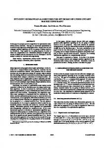
4.3 Graph Algorithms A realm can be interpreted as a spatially embedded planar graph [GüS93a]. Hence, a lines or a regions object defined over such a realm can also be regarded as a planar graph G = (V, E) where the vertex set V is the set of all end points of the segments and the edge set E is the set of all segments of the object. Note that such an embedded planar graph represents not only the usual incidence relationships between nodes and edges, but also the neighbourhood relationship among segments incident to the same node. This graph-theoretic view offers two primitive operations, illustrated in Figure 4, that are crucial for the algorithms discussed in this section: For a given halfsegment, (i) find its two neighbours incident to the same node w.r.t. the counter-clockwise order, and (ii) find the “partner halfsegment” representing the same segment (which is equivalent to following an edge of the graph).
Figure 4: Relationships in a graph Basically, the data structure needed to support these two primitives in O(1) time is an adjacency list for each node containing the outgoing edges in counter-clockwise order. As it happens, the halfsegment sequence representing a lines or regions object is already close to the desired structure because it contains all halfsegments with the same dominating point as a compact subsequence in counterclockwise order (this fact has already been used in algorithm ll_intersects). What is needed additionally is a pointer from each halfsegment to the partner halfsegment. For convenience, we also doubly link the halfsegments around a node. Figure 5 shows a lines object and its graph representation in two arrays Edge and Node. Array Node
Array Edge
p8 p6
p1
p4
s1 p2
s3 s2 p3
s6
s5 p7
s4 p5
Figure 5: Graph Representation of a lines object
pred succ link node_index
index on_stack
index
h
1
h 1l
1
1
5
1
1
false
2
h 2l
3
3
4
2
2
false
3
h 3l
2
2
6
2
3
false
4
h 2r
4
4
2
3
4
false
5
h 1r
8
6
1
4
5
false
6
h 3r
5
7
3
4
6
false
7
h 4l
6
8
9
4
7
false
8
h 5l
7
5
10
4
8
false
9
h 4r
9
9
7
5
10
h 5r
10
10
8
6
11
h 6l
11
11
12
7
12
h 6r
12
12
11
8
−
16
−
This is essentially the temporary representation of a lines or regions object used in the ROSE system as a basis for graph algorithms. In array Edge, field h contains the halfsegment. The fields pred and succ contain the indexes of the preceding and succeeding halfsegments in the counter-clockwise order; link is the index of the partner halfsegment. The field node_index points into the second array Node. The data structure definition and an algorithm for creating this temporary representation are shown at the bottom of this page. In algorithm init_edge_and_node_array, the while-loop is executed once for each halfsegment. All operations within the loop need constant time except for linking a right with its corresponding left halfsegment which requires O(log n) time where n is the number of halfsegments of the lines or regions object. Hence the whole algorithm has time complexity O(n log n). After initialization of the arrays, for an index of an element we can find its predecessor, successor, opposite halfsegment, and node information in constant time. This graph-theoretic view is used to realize the executable operators l_interior, r_contour, l_count, and r_count which have the following signature: lines regions lines regions
→ → → →
regions lines int int
l_interior r_contour l_count r_count
Here l_interior determines a regions object formed from the areas enclosed by segments of a lines object, r_contour returns a lines object formed from the segments of only the outer cycles of the faces of a regions object (holes are omitted). The other two operations return the number of components const type
var
MaxComp = ...; EdgeRec = record h : HN; pred, succ : cardinal; link, node_index : cardinal; end; NodeRec = record on_stack : boolean; end; Edge = array [1..MaxComp] of EdgeRec; Node = array [1..NoOfPoints] of NodeRec;
algorithm init_edge_and_node_array input: A lines object L (or a regions object R) output:The two arrays Edge and Node begin topV := 0; topE := 0; old_dp := (m, m); (* outside of the realm *) L := select_first(L); while not end_of_hs(L) do topE := topE + 1; h := get_hs(L); (* Let h = (s, d). *) Edge[topE].h := h; act_dp := dp(h); if (act_dp ≠ old_dp) or (topV = 0) then
(* New or first point reached. *) topV := topV + 1; Node[topV].on_stack := false; Edge[topE].node_index := topV; Edge[topE].succ := topE; Edge[topE].pred := topE; else (* The same dominating point. *) Edge[topE].node_index := topV; (* Produce doubly-linked ring. *) Edge[topE].pred := topE − 1; Edge[topE].succ := Edge[topE − 1].succ; Edge[topE − 1].succ := topE; Edge[Edge[topE].succ].pred := topE; end-if; if d = right then < Compute index i of the corresponding left halfsegment of the array Edge in the range 1 to topE by using binary search. > Edge[topE].link := i; Edge[i].link := topE; end-if; old_dp := act_dp; L := select_next(L); end-while; return Edge, Node; end init_edge_and_node_array.
−
17
−
which is the number of blocks (connected components) for a lines object and the number of faces for a regions object. As an example, we show the algorithm for r_contour. The main problem is the assignment of the segments to the correct outer and hole cycles which according to the face definition is unique [GüS93a]. According to that definition, the regions object in Figure 6(a) consists of two faces rather than of a single face with a hole.
(a)
Figure 6: Traversal of Cycles
(b)
An important observation is that for the first halfsegment of any cycle (with respect to the order of halfsegments) we can decide whether it belongs to an outer cycle or a hole. It is a left halfsegment and belongs to an outer cycle iff the attribute InsideAbove has been set, otherwise to a hole. We adopt the following strategy: If for a given left halfsegment it is known that it belongs to an outer cycle, then we traverse the graph forming a minimal cycle containing that segment. This works as follows: For the given halfsegment, get the partner halfsegment (i.e. follow the edge). From the partner, go around that node to the predecessor in the counter-clockwise order. Follow that edge, etc. As soon as the node of the initial segment is reached again, a complete cycle has been found and its segments can be marked as outer segments. This strategy works fine for the regions object in Figure 6(a) where it correctly determines the left face. However, in Figure 6(b) the cycle would include the hole segments. Therefore the strategy is refined as follows: If the first segment belongs to an outer cycle, then try to form a minimal cycle traversing the graph as described above. Put each encountered halfsegment on a stack and mark its node as being on_stack. As soon as a node is encountered which is on the stack already, two cases are possible: • Case 1. This is the node of the initial segment. Then a complete outer cycle has been found. Remove all segments from the stack, marking them as outer segments, and also from the graph. Repeat the procedure for the remaining segments. • Case 2. This is not the initial node. Then a hole cycle has been found. Remove segments from the stack until the current node is found there, marking them as hole segments. Remove these segments also from the graph. Then continue building the outer cycle. - Before removing segments from the stack one must store the next segment of the outer cycle in order to avoid continuing with some other face that may lie in the hole, as shown in Figure 6(b). If the first segment belongs to a hole, then try to form a maximal cycle by going always to the successor around a node. Apart from that, proceed in the same way as for outer cycles. However, if here a node is encountered which is not the initial one, then a cycle belonging to another hole has been found sharing a vertex with the hole cycle of the initial segment. On the next page we present two algorithms. Algorithm cycle_classification classifies the segments of a regions object as outer or hole segments, following the strategy just discussed. Here the type EdgeRec is extended by the fields visited and inside_above. The first field is initialized by the value
− algorithm cycle_classification input: A regions object R output:A modified regions object R whose halfsegments obtain the attribute HoleSegment if they belong to a hole and OuterSegment otherwise. begin init_edge_and_node_array(R); top := 0; for i := 1 to < number of segments in Edge > do if not Edge[i].visited then if Edge[i].inside_above then (* Outer cycle. *) Node[Edge[i].node_index].on_stack := true; push(i); Edge[i].visited := true; first_node_index := Edge[i].node_index; l := Edge[i].link; push(l); Edge[l].visited := true; repeat j := Edge[l].node_index; if not Node[j].on_stack then Node[j].on_stack := true; j := Edge[l].pred; push(j); Edge[j].visited := true; l := Edge[j].link; push(l); Edge[l].visited := true; else if j = first_node_index then while top > 0 do (* Outer cycle. *) j := pop(); < Remove Edge[j] from the graph. >; < Set attribute OuterSegment for Edge[j]. >; Node[Edge[j].node_index].on_stack := false end-while else (* Hole cycle. *) rem := Edge[l].pred; count := 0; repeat k := pop(); < Remove Edge[j] from the graph.>; < Set attribute HoleSegment for
18
− Edge[k]. >; Node[Edge[k].node_index].on_stack := false; if Edge[k].node_index = j then count := count + 1 end-if until (j = Edge[k].node_index) and (count = 2); push(rem); Edge[rem].visited := true; l := Edge[rem].link; push(l); Edge[l].visited := true; end-if until top = 0; else (* Hole cycle. *) < Proceed analogously. > end-if end-if end-for; end cycle_classification.
algorithm r_contour input: A regions object R output:A lines object L containing the halfsegments of all outer cycles of R. begin L := new(); cycle_classification(R); R := select_first(R); while not end_of_hs(R) do attr := get_attr(R); if OuterSegment ∈ attr then h := get_hs(R); L := insert(L, h); end-if; R := select_next(R); end-while; return L; end r_contour.
false; the latter field is true if a halfsegment of the regions object has the attribute InsideAbove. A variable top always contains the index of the top stack element; it is implicitly changed by the stack operations push and pop. “Remove Edge[j] from the graph” means remove the edge from the cycle of segments around its node. This algorithm requires O(n log n) time for a regions object with n halfsegments due to the included preprocessing step for computing the Edge and Node arrays; apart from that it needs only O(n) time. The second algorithm r_contour then computes the contour of a regions object by using the first algorithm. After cycle_classification has been done, this is trivial and needs only O(n) additional time. The total time for r_contour, as presented, is O(n log n). The algorithm for l_interior first follows a similar strategy as cycle_classification to extract only complete cycles from a lines object. It then uses plane sweep to remove any cycles enclosed by other cycles. This algorithm needs O(n log n) time. Computing the components in a lines object (l_count)
−
19
−
can be done by a simple depth-first traversal [AhHU83]. Determining the number of components (faces) in a regions object is also a by-product of cycle classification. The last two algorithms require O(n) time once the graph representation has been constructed.
4.4 Special Algorithms The diameter operator of the ROSE algebra determines the maximal extent of an object, that is, the maximal distance between any two vertices. The implementation of the corresponding three executable operators p_diameter, l_diameter, and r_diameter uses special algorithms different from the three techniques mentioned before. The computation of all distances between any two points of an object is too time-consuming. To reduce the number of elements, we determine the convex hull of the object, since the diameter of the convex hull is equal to the diameter of the whole object [PrS85]. An algorithm which calculates the convex hull of the point set of a simple polygon in linear time can be found in [Me84]. An algorithm which computes the diameter of a convex polygon in linear time is shown in [PrS85]. The combination of these two algorithms is used in the ROSE system to realize the three diameter operations in O(n) time for an object with n points or halfsegments.
5
Implementation
In this section we discuss in more detail the actual representation of ROSE objects and some differences between the conceptual view of algorithms, as presented above, and the actual procedures in the system. On the next page, the representation of a regions object is shown (for points and lines objects it is similar). A regions object is given as (a pointer to) a record whose last component is an array elem; one can dynamically allocate storage to represent regions objects of any desired size. The array serves as a storage pool for three different kinds of nodes representing halfsegments, faces, or holes, respectively. Halfsegments are organized in an AVL-tree to allow for updates in O(log n) time; additional pointers connect all halfsegments within the object, within a face, and within a cycle (outer cycle or hole cycle) into linked lists ordered in halfsegment order. Additionally all faces, and for each face its holes, are linked. Hence the complete structure of a regions object is explicitly represented and access operations are offered (in the module hiding this representation) to perform all kinds of scans in linear time. Furthermore, bounding boxes are stored for the object, each face, and each hole. The record contains general information about the object such as the root segment of the AVL-tree, fields for perimeter, diameter and area; the attr field tells which of these values have already been computed for this particular object. In Section 4.3, we have described the graph algorithms from a conceptual point of view. What really happens is that the graph structure is analyzed at the time of closing an object, that is, after all segments have been inserted. More precisely, the construction of a regions object consists of the following steps: • Allocate storage, insert n halfsegments into the AVL-tree. To close the object: • Perform an inorder traversal of the tree to link all halfsegments of the object; compute the bounding box. • Use plane sweep to compute InsideAbove attributes (sketched in Section 4.2). • Use algorithm cycle_classification (including init_edge_and_node_array) to attach a
−
20
−
FROM Primitives IMPORT (* type *) BBOX, HALFSEGMENT, POINT, SEGMENT; TYPE OBJATTRIBS ATTRIBSET COMPATTRIBS COMPSET FIELDTYPE SELECTTYPE
= = = = = =
(Closed, Perimeter, Diameter, Area); SET OF OBJATTRIBS; (InsideUp, HoleSegment); SET OF COMPATTRIBS; (HalfsegField, FaceField, HoleField); (RegionsSelected, FaceSelected, CycleSelected);
REGIONSELEM = RECORD CASE kind : FIELDTYPE OF HalfsegField: h : HALFSEGMENT; (* Key-element. *) attrib : COMPSET; (* Element status.*) left : CARDINAL; (* AVL-tree. *) right : CARDINAL; height : CARDINAL; next_in_regions : CARDINAL; (* In order lists.*) next_in_face : CARDINAL; next_in_cycle : CARDINAL; | FaceField: face_bbox : BBOX; (* Face bounding box. *) first_in_face : CARDINAL; (* First halfsegment. *) last_in_face : CARDINAL; (* (Help pointer.) *) last_in_cycle : CARDINAL; (* (Help pointer.) *) first_hole : CARDINAL; (* First hole in face. *) last_hole : CARDINAL; (* (Help pointer.) *) next_face : CARDINAL; (* Face list. *) | ELSE hole_bbox : BBOX; (* Hole bounding. *) first_in_hole : CARDINAL; (* First Halfsegment. *) last_in_hole : CARDINAL; (* (Help pointer.) *) next_hole : CARDINAL; (* Hole list. *) END; END; REGIONS
= POINTER TO RECORD attr : ATTRIBSET; (* The object’s status. *) perimeter : REAL; (* Length of Segments. *) diameter : REAL; (* Diameter. *) area : REAL; (* Area of object. *) bbox : BBOX; (* Bounding box. *) count : CARDINAL; (* Number of faces. *) holes : CARDINAL; (* Number of holes. *) free : CARDINAL; (* Number of free fields. *) first_idx : CARDINAL; (* Idx of smallest halfseg. *) face_idx : CARDINAL; (* Idx of first face. *) root_idx : CARDINAL; (* Idx of root of AVL-tree. *) act_idx : CARDINAL; (* Idx of selected halfseg. *) act_face : CARDINAL; (* Idx of selected face. *) sel_kind : SELECTTYPE; (* Kind of traversal. *) max_idx : CARDINAL; (* Idx of largest half-field. *) act_hole : CARDINAL; (* Idx of selected hole. *) elem : ARRAY [1..MaxInRegions] OF REGIONSELEM END;
unique cycle number to each segment. • Use a second plane sweep (a variant of the previous one) to determine for each hole segment the cycle number of the outer cycle of its surrounding face. • In a final scan of the complete list of segments, link all segments within faces and cycles (this is possible since each segment has now an associated cycle number and face number) and compute the remaining information such as bounding boxes, links of faces and holes, etc. Clearly the whole construction takes no more than O(n log n) time and O(n) space. An analogous strategy is used for the more simple lines and points objects. Because all this information is now explicitly available in the data structures, the algorithms and running times for some operations change: all no_of_components algorithms perform a simple lookup in O(1) time. The algorithm for r_contour simply scans the list of faces and for each face the list of segments of its outer cycle which requires only O(k log k) time (where k is the size of the result object). For operators computing diameter, length, area and perimeter, only the first call takes O(n) time; the value is then stored with the object
−
21
−
so that subsequent calls are lookups in O(1) time. Further differences between the algorithms described above and the actual procedures result from: • Use of filter techniques. Most operations first compare bounding boxes of objects, some in a second step also component bounding boxes, in order to avoid running the more expensive algorithms on the actual halfsegments, whenever possible. Such strategies are well-known (e.g. [OrM88, Gü94]). • Estimating the size of the result is necessary in all operations constructing new objects to allocate the appropriate amount of storage for them. For further details, we recommend the study of [Ri95].
6
Conclusions
We have described the implementation of a large part of a spatial algebra for database systems - that is, the almost complete implementation of the first three groups of operators of the ROSE algebra (only the dist operator is missing) which deal with “atomic” objects (whereas the fourth group manipulates set of database objects). Use of high-level primitives has made it possible to describe a relatively large number of algorithms in compact, precise notation. We are not aware of any similar work - treating a whole algebra by giving precise algorithms including analysis of their complexity. The fact that ROSE objects are realm-based has led to relatively simple, efficient, and numerically robust algorithms. All manipulations of objects are discrete (entirely based on integer arithmetics); real numbers occur only to describe properties such as length or area of objects. A crucial concept is the use of ordered halfsegment sequences as a base representation of objects. Manipulation of such sequences in parallel traversal or plane sweep implements most operations efficiently. On the other hand, we have also shown how the structure of objects (faces, holes, etc.) can be determined by graph algorithms and be represented in the data structures. The ROSE system is available for study or use, currently in the form of a stand-alone Modula-2 library [Ri95]. It is in principle suitable for use in database systems since all objects have compact representations. However, for a serious integration it is necessary to solve the problem of managing very large ROSE objects in a way that is compatible with the DBMS object and storage management. We are currently working on the definition and implementation of a general “algebra interface” between an external implementation of a system of data types and a database system. The ROSE algebra will be made available under such an interface and integrated into the Gral system [Gü89, BeG92]. In this approach, it is only necessary to replace the array components “at the end” of object representations by identifiers of so-called “database arrays” which behave exactly like ordinary arrays but have their own page sequences and buffer management and interact properly with DBMS transaction management. This is a straightforward, technical modification of the ROSE algebra; algorithms remain unchanged. Another aspect of integration into a database system is the connection to the underlying realms, in particular the propagation of updates from the realm to ROSE objects in a database [GüS93a]. Our realm implementation is almost completed. All these integration aspects will be described in a forthcoming paper.
−
22
−
Appendix The structure of this table is explained in Section 2. In column “time complexity” (TC), n denotes the total size of the operand(s), m the size of the regions operand (only used if there is just one), and k the size of the result object. Descriptive Operator geo × geo → bool
Executable Operator
O(n)
≠
pp_unequal, ll_unequal, rr_unequal
x
O(n)
pp_disjoint, ll_disjoint
x
O(n)
rr_disjoint
x
O(n log n)
pr_inside, lr_inside
x
O(n log m)
rr_inside
x
O(n log n)
area_disjoint
rr_area_disjoint
x
O(n log n)
edge_disjoint
rr_edge_disjoint
x
O(n log n)
rr_edge_inside
x
O(n log n)
rr_vertex_inside
x
O(n log n)
vertex_inside intersects
meets
border_in_common
area × area → bool
points × ext → bool
TC
x
edge_inside
ext1 × ext2 → bool
G
pp_equal, ll_equal, rr_equal
inside
regions × regions → bool
PS
=
disjoint
geo × regions → bool
PT
ll_intersects
x
O(n)
lr_intersects, rl_intersects
x
O(n log m)
rr_intersects
x
O(n log n)
ll_meets
x
O(n)
lr_meets, rl_meets
x
O(n log m)
rr_meets
x
O(n log n)
ll_border_in_common, lr_border_in_common, rl_border_in_common, rr_border_in_common
x
O(n)
adjacent
rr_adjacent
x
O(n log n)
encloses
rr_encloses
x
O(n log n)
on_border_of
pl_on_border_of, pr_on_border_of
x
O(n)
points × points → points
intersection
pp_intersection
x
O(n + k log k)
lines × lines → points
intersection
ll_intersection
x
O(n + k log k)
regions × regions → regions
intersection
rr_intersection
x
O(n log n)
regions × lines → lines
intersection
rl_intersection
x
O(n log m + k log k)
geo × geo → geo
plus
pp_plus, ll_plus rr_plus
x
O(n + k log k) x
O(n log n)
−
Descriptive Operator geo × geo → geo
23
−
Executable Operator minus
pp_minus, ll_minus
PT
G
x
rr_minus ext1 × ext2 → lines
PS
TC O(n + k log k)
x
O(n log n)
common_border
ll_common_border, lr_common_border, rl_common_border, rr_common_border
x
O(n + k log k)
ext → points
vertices
l_vertices, r_vertices
x
O(n + k log k)
regions → lines
contour
r_contour
x
O(n log n) / O(k log k)
lines → regions
interior
l_interior
x
O(n log n)
geo → int
no_of_components
p_no_of_components
x
l_no_of_components, r_no_of_components geo1 × geo2 → real
geo → real lines → real regions → real
dist
diameter length area perimeter
O(n) / O(1) x
O(n log n) / O(1)
p_diameter, l_diameter, r_diameter
special algorithm
O(n) / O(1)
l_length
x
O(n) / O(1)
r_area
x
O(n) / O(1)
r_perimeter
x
O(n) / O(1)
pp_dist, pl_dist, pr_dist, lp_dist, ll_dist, lr_dist, rp_dist, rl_dist, rr_dist
References [AhHU83]
Aho, A.V., J.E. Hopcroft, and J.D. Ullman, Data Structures and Algorithms. Addison-Wesley, Reading, Massachusetts, 1983.
[BeG92]
Becker, L., and R.H. Güting, Rule-Based Optimization and Query Processing in an Extensible Geometric Database System. ACM Transactions on Database Systems 17 (1992), 247-303.
[GrY86]
Greene, D., and F. Yao, Finite-Resolution Computational Geometry. Proc. 27th IEEE Symp. on Foundations of Computer Science, 1986, 143-152.
[Gü89]
Güting, R.H., Gral: An Extensible Relational Database System for Geometric Applications. Proc. of the 15th Intl. Conf. on Very Large Databases (Amsterdam, The Netherlands), 1989, 33-44.
[Gü93]
Güting, R.H., Second-Order Signature: A Tool for Specifying Data Models, Query Processing, and Optimization. Proc. ACM SIGMOD Conf. (Washington, USA), 1993, 277-286.
[Gü94]
Güting, R.H., An Introduction to Spatial Database Systems. VLDB Journal 3, 4 (1994) (Special Issue on Spatial Database Systems), 357-399.
[GüS93a]
Güting, R.H., and M. Schneider, Realms: A Foundation for Spatial Data Types in Database Systems. Proc. of the 3rd Intl. Symposium on Large Spatial Databases (Singapore), 1993, 14-35.
[GüS93b]
Güting, R.H., and M. Schneider, Realm-Based Spatial Data Types : The ROSE Algebra. Fernuniversität Hagen, Informatik-Report 141, 1993. To appear in the VLDB Journal.
[KaM85]
Karlsson, R.G., and J.I. Munro, Proximity on a Grid. Proc. of the 2nd Symp. on Theoretical Aspects of Computer Science, Springer-Verlag, LNCS 182, 1985, 187-196.
[KaO88a]
Karlsson, R.G., and M.H. Overmars, Scanline Algorithms on a Grid. BIT 28 (1988), 227-241.
−
24
−
[KaO88b]
Karlsson, R.G., and M.H. Overmars, Normalized Divide-and-Conquer: A Scaling Technique for Solving Multi-Dimensional Problems. Information Processing Letters 26 (1988), 307-312.
[KeK81]
Keil, J.M., and D.G. Kirkpatrick, Computational Geometry on Integer Grids. Proc. of the 19th Annual Allerton Conference on Communication, Control, and Computing, 1981, 41-50.
[Kl83]
Klaeren, H.A., Algebraische Spezifikation. Springer Verlag, Berlin, 1983.
[Me84]
Mehlhorn, K., Data Structures and Algorithms 3: Multidimensional Searching and Computational Geometry. Springer Verlag, 1984.
[Mü85]
Müller, H., Rastered Point Location. Proc. Workshop on Graphtheoretic Concepts in Computer Science, Trauner Verlag, 1985, 281-293.
[OrM88]
Orenstein, J., and F. Manola, PROBE Spatial Data Modeling and Query Processing in an Image Database Application. IEEE Trans. on Software Engineering 14 (1988), 611-629.
[Ov88a]
Overmars, M.H., Efficient Data Structures for Range Searching on a Grid. Journal of Algorithms 9 (1988), 254-275.
[Ov88b]
Overmars, M.H., New Algorithms for Computer Graphics. Advances in Computer Graphics, Eurographics Seminars, Springer Verlag, 1988, 3-19.
[Ov88c]
Overmars, M.H., Computational Geometry on a Grid: An Overview. Theoretical Foundations for Computer Graphics and CAD, Springer Verlag, 1988, 167-184.
[PrS85]
Preparata F.P., and M.I. Shamos, Computational Geometry. Springer Verlag, 1985.
[Ri95]
de Ridder, T., The ROSE System. Modula-2 Program System (Source Code). Fernuniversität Hagen, Praktische Informatik IV, Software Report 1, 1995. Available as a LaTeX file for printing and/or as a compressed collection of ASCII files.
[Ya92]
Yao F.F., Computational Geometry. Algorithms and Complexity. Handbook of Theoretical Computer Science, vol. A, Elsevier Science Publishers B.V., 1992, 343-389.