|65
https://doi.org/10.3311/PPee.11744 Creative Commons Attribution b
Periodica Polytechnica Electrical Engineering and Computer Science, 62(3), pp. 65–73, 2018
Improved Modified DTC-SVM Methods for Increasing the Overload-capability of Permanent Magnet Synchronous Motor Servo- and Robot Drives – Part 1 Tibor Vajsz1*, László Számel1 Department of Electric Power Engineering, Faculty of Electrical Engineering and Informatics, Budapest University of Technology and Economics, H-1521 Budapest, P.O.B. 91, Hungary * Corresponding author, e-mail:
[email protected] 1
Received: 24 November 2017, Accepted: 14 May 2018, Published online: 25 May 2018 Abstract Direct torque control with space vector modulation (DTC-SVM) is one of the most popular methods in the case of permanent magnet synchronous motor drives due to its excellent torque-control capabilities. This method facilitates a very high torque-control dynamic performance which is an especially important requirement in the field of servo- and robotic applications, thus making DTC-SVM a natural choice in these cases. In this article a novel Improved Modified DTC-SVM (IMDTC-SVM) method is presented and it is proven that this method has a very high overload-capability and is stable during overload-conditions, while the torque-control dynamics and the torque-ripple generated are practically identical with those of the classical DTC-SVM and the MDTC-SVM. Keywords permanent magnet synchronous motor, direct torque control, space vector modulation, servo drive, robot drive, frequency converter, electric drive
1 Introduction Permanent magnet synchronous motors (PMSMs) are nowadays extensively used which can be contributed mainly to their high power-density and high efficiency [1]. They are widely used in electric vehicles [2], in high-speed drives [3, 4] and in servo drives [5], along with stepping motors [6]. Many methods have been developed for controlling the electromagnetic torque of PMSMs. One of these methods is called direct torque control (DTC) which is famous for its excellent dynamic torque-control capabilities in the case of PMSMs, induction motors, etc. [7-13]. The method has been generalized for network-connected voltage source converters providing an excellent dynamic control of the power flow between the network and the DC-bus [14-18]. This is called Direct Power Control (DPC) [14-18]. However, DTC produces excessive amount of torque-ripple during operation along with varying switching frequency [7, 11], which are undesirable in the case of servoand robot drives. DTC-SVM grants fixed switching frequency and the torque-ripple is significantly reduced compared to DTC, while the dynamics of the torque-control is essentially identical to that of the traditional DTC [19-21]. Therefore, DTC-SVM is considered as one of the
research areas that is currently in the centre of interest within the DTC-topic [22-26]. However, the overload-capability of DTC-SVM methods is an issue that has not been thoroughly investigated yet. This article focuses on this issue and proposes an Improved Modified DTC-SVM (IMDTC-SVM) method that has a significantly increased overload-capability even compared to that of the MDTC-SVM introduced in [27] and the classical DTC-SVM. Therefore, this article is intended to continue the thread of [27]. 2 Terminology, notations The basic equations of permanent magnet synchronous motor drives are well-detailed in [11, 27], for the sake of convenience only the equations most related to the topic of this article are detailed. The terminology, the abbreviations and the notations will be the same as in [27], for detailed information see [27]. Also, like [27], this article assumes a surface-mounted permanent magnet synchronous motor as the majority of the permanent magnet synchronous motor servo- and robot drives fall into this category. This means that the direct- and
Cite this article as: Vajsz, T., Számel, L. "Improved Modified DTC-SVM Methods for Increasing the Overload-capability of Permanent Magnet Synchronous Motor Servo- and Robot Drives – Part 1", Periodica Polytechnica Electrical Engineering and Computer Science, 62(3), pp. 65–73, 2018. https://doi.org/10.3311/PPee.11744
and Számel 66|Vajsz Period. Polytech. Elec. Eng. Comp. Sci., 62(3), pp. 65–73, 2018
the quadrature-axis synchronous inductances are nearly identical and thus the reluctance torque is negligible. 3 Improved modified DTC-SVM For surface-mounted permanent magnet synchronous motors the electromagnetic torque is as follows: m=
3 ψ p ×ψ p . Ld 2
(1)
Where: p: the number of pole-pairs ψ p : the poleflux-vector ψ : the stator flux vector Ld: the direct-axis synchronous inductance (Lq = Ld). This means that the absolute value of the electromagnetic torque is: m=
3 ψ pψ sin δ p Ld 2
Fig. 1 Flux vector definitions
(2)
where ψ p is the amplitude of the poleflux-vector, ψ is the amplitude of the stator flux vector and δ is the load-angle. According to Fig. 1 the stator flux vector can be expressed as:
ψ = ψ d + ψ q
(3)
Fig. 2 IMDTC-SVM
where ψ d and ψ q are the direct- and the quadrature-axis components of the stator flux vector. Based on Fig. 1 Eq. (2) can be rewritten as: m=
3 ψ pψ q p Ld 2
(4)
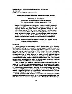
where ψq is the amplitude of the quadrature-axis component of the stator flux vector. Fig. 2 shows the block diagram of improved modified DTC-SVM (IMDTC-SVM). An improved estimator (IEST) is used to estimate the variables that are required by the improved predictive controller (IPC) in order to perform the control algorithm. The improved predictive controller computes the voltage vector reference that is synthesized by the two-level voltage source inverter (VSI) using space vector modulation (SVM). (A detailed description of space vector modulation can be read in [11, 27-29].) The improved estimator is the combination of the modified estimator (MEST) detailed in [27] and the estimator of classical DTC-SVM (see [27]) because it computes both the load-angle and the electromagnetic torque. The improved predictive controller consists of five blocks: the stator flux amplitude reference controller
Fig. 3 IEST
(ψ ref ctrl), the reference controller (Ref.ctrl), the ψ-controller (ψ ctrl), the δ-controller (δ ctrl) and the adaptive voltage vector calculator (AVVC). The ψ ref -controller uses the electromagnetic torque reference (mref) and the electromagnetic torque (m) in order to compute the stator flux amplitude reference signal (ψ ref,m). The ψ ref -controller is a special P-type controller. It uses the difference of the absolute values of mref and m as an error-signal. The gain of the P-type controller is denoted with Ap on Fig. 5.
|67
Vajsz and Számel Period. Polytech. Elec. Eng. Comp. Sci., 62(3), pp. 65–73, 2018
is used in order to make the tuning of the complete control system easier. The reference controller receives mref and ψ ref,m and synthesizes the stator flux vector reference (ψ ref and δref ). Fig 6 shows the block diagram of the reference controller. Based on Eq. (4) a reference value for ψq (ψq,ref) is computed from mref . From ψ ref,m and ψq,ref ψd,ref is derived using the following equation: ψ d , ref = ψ ref , m 2 −ψ q , ref 2 .
Fig. 4 IPC
(7)
Due to the fact that ψ ref,m2 − ψq,ref 2 can be negative, its absolute value must taken in order to form ψd,ref . Based on ψd,ref and ψq,ref a new stator flux vector reference is synthesized using the following equations:
ψ ref = ψ d , ref 2 + ψ q , ref 2 δ ref = arctan Fig. 5 ψ ref -controller
Also, there is a torque limit signal (mlimit ) which is used for the activation/deactivation of the control mechanism. This means that the function and limit block ( fcn() and Limit on Fig. 5) outputs the nominal stator flux amplitude (ψ nom ) if the control mechanism is deactivated. The control mechanism is active if and only if both mref and m are greater than mlimit or both mref and m are smaller than (−1) * mlimit . If the control mechanism is active the output without limitation is:
(
)
ψ ref , m = Ap mref − m + ψ nom .
(5)
The output of the controller is limited between ψ nom and the maximal stator flux amplitude which – by neglecting the stator resistance – can be expressed as:
ψ max = v1,max ωe , nom .
ψ q , ref ψ d , ref
.
(9)
Both ψ ref and δref are limited at the output of the reference controller: ψ ref is limited between ψ nom and ψ max and δref is limited between −90° and 90° (arctan naturally limits between these values). Fig. 7 shows the block diagram of the δ-controller. A PI-controller is used in order to synthesize the δ-increment signal like in the case of classical DTC-SVM and MDTC-SVM. However, the δ-increment signal is added to δ in order to form the load-angle reference that is fed towards the AVVC (δref, AVVC ) and limitation (Lim-block on Fig. 7) is applied for δref, AVVC , instead of limiting for Δδ like in the case of classical DTC-SVM and MDTC-SVM. δref, AVVC is limited between −90° and 90°. Also, there is a limit bit which is used for halting the integration in the PI-controller if the output has reached a limit. At the end
(6)
Where: v1,max: the maximal amplitude of the stator voltage vector reference, v1,max = vdc 3 ωe,nom: the nominal electrical angular speed, ωe,nom = 2πfe,nom , where fe,nom is the nominal frequency. Taking the absolute values of mref and m is necessary for proper operation because mref and m can be either positive or negative while the stator flux amplitude reference must be positive. The activation/deactivation mechanism
(8)
Fig. 6 Reference controller
Fig. 7 δ-controller
and Számel 68|Vajsz Period. Polytech. Elec. Eng. Comp. Sci., 62(3), pp. 65–73, 2018
δref, AVVC is added to the actual angle of the stator flux vector (γ) in order to form the reference angle of the stator flux vector that is fed to the AVVC (γref, AVVC). Fig. 8 shows the block diagram of the ψ-controller. The basic principle is similar to the case of the δ-controller. A PI-controller is used to synthesize the ψ-increment signal which is added to ψ and limitation is applied for the stator flux amplitude reference that is fed to the AVVC (ψ ref, AVVC). ψ ref, AVVC is limited between ψ nom and ψ max . Also, there is a limit bit which is used for halting the integration in the PI-controller if the output has reached a limit. According to Fig. 4 ψ ref, AVVC and γref, AVVC are fed to the AVVC. The voltage vector calculator is adaptive because it changes its structure in the function of angular velocity (ω) / speed. If the absolute value of the rotor speed is below a certain limit the voltage vector reference is calculated as follows: vx , ref =
v y , ref =
ψ ref , AVVC cos ( γ ref , AVVC ) −ψ cos ( γ ) Ts
ψ ref , AVVC sin ( γ ref , AVVC ) −ψ sin ( γ ) Ts
+ Rix
(10)
+ Ri y
(11)
v1 = vx2, ref + v y2, ref
α1 = arctan
v y , ref vx , ref
(12) (13)
where Ts is the torque-control loop sample time. If the absolute value of the rotor speed has reached the aforementioned speed limit Eq. (10) and Eq. (11) are modified to the following form: vx , ref =
v y , ref =
ψ ref , AVVC cos ( γ ref , AVVC ) −ψ cos ( γ ) Ts
ψ ref , AVVC sin ( γ ref , AVVC ) −ψ sin ( γ ) Ts
(14)
.
(15)
This control structure changing mechanism is useful in increasing the overload capability of the drive system. The speed-limit is set in the high-speed region, close to the nominal speed. During operation on high-speeds the
Fig. 8 ψ-controller
back-EMF in the stator is high and with heavy overloads the current-limiter can get activated. If the current-limiter is activated it switches the zero voltage vector on the motor terminals which with the help of the back-EMF in the stator leads to the rapid change of the amplitude of the stator current vector. The frequent activation/deactivation of the current-limiter causes spikes in the amplitude of the stator current vector and in the electromagnetic torque. However, the aforementioned current-spikes are fed back through the Ri-terms in Eq. (10) and Eq. (11) to the VVC if a standard VVC is used. This leads to disturbances in the voltage vector calculation which results in further spikes in the amplitude of the stator current vector and in the electromagnetic torque, which are again fed back through the Ri-terms to the standard VVC and so on. This phenomenon leads to deteriorated control performance and to a reduction in the overload-capabilities. Therefore, the Ri-terms are not included in the calculation of the voltage vector reference on high-speeds in the case of the AVVC and thus the AVVC is an open-loop structure on high-speeds. On lower speeds however, the AVVC is still a closedloop structure and uses Eq. (10) and Eq. (11) in order to compute the voltage vector reference. This is because on lower speeds the back-EMF in the stator is lower, therefore the activation of the current-limiter does not cause such a steep change in the amplitude of the stator current vector which means that the current-spikes are negligible and thus the disturbances in the calculation of the voltage vector reference are negligible as well. If the voltage vector calculator was using Eq. (14) and Eq. (15) on lower speeds instead of Eq. (10) and Eq. (11) the overload-capability of the drive would be reduced due to the control-error that is caused by the neglecting of the Ri-terms in Eq. (10) and Eq. (11). As it will be seen from the simulation results the overload-capability of IMDTC-SVM is superior to that of either the MDTC-SVM or the classical DTC-SVM. This is due to the following features of IMDTC-SVM: • The forming of the stator flux amplitude reference signal (ψ ref ) is dependent on the electromagnetic torque reference (mref ), whereas in the case of both MDTC-SVM and classical DTC-SVM the two are independent of each other [27]. • There is a stator flux amplitude reference controller which increases the stator flux amplitude reference signal if necessary. • Improved limitation-techniques are used in the δ-controller and in the ψ-controller.
|69
Vajsz and Számel Period. Polytech. Elec. Eng. Comp. Sci., 62(3), pp. 65–73, 2018
• The voltage vector calculator is adaptive instead of a standard one. These features altogether significantly increase the overload-capability of IMDTC-SVM compared to either the MDTC-SVM or the classical DTC-SVM. 4 Simulation results for torque-ripple and torquecontrol dynamics Simulation was carried out for a synchronous servo motor in Matlab-Simulink environment, using the same parameters as in [27]. The parameters can be found in Table 1 of [27]. Investigations were carried out for the normal operation region only. The simulation used the same optimized switching strategy for space vector modulation as in [27]. Current-limitation was also implemented during the investigations in the same way as in [27]. Current-limit was set to 600 % of the nominal current during the simulations like in [27]. mlimit was set to 5.5 Nm. The simulated process is the same as in 2.4 and 3.1 of [27], except that the torque-reference is not limited to 3 Nm at the beginning of the process. Instead, it will be limited to 8 Nm during the whole process. Fig. 9 shows the speed vs. time, while Fig. 10 shows the electromagnetic torque vs. time for a 3000 rpm speed-reference. The time is given in milliseconds on the horizontal axis of both figures. Table 1 shows the results for the RMS of the torque-ripple, which is shown in percentage of the mean-torque. According to Table 1 of this article and Table 2 and Table 3 of [27] there is no significant difference between classical DTC-SVM, MDTC-SVM and IMDTC-SVM in regard of the RMS of the torque-ripple. Also, based on
Fig. 9 Speed vs. time for a 3000 rpm speed-reference
Fig. 10 m vs. time for a 3000 rpm speed-reference
Table 1 RMS torque-ripple in percentage of the mean-torque for IMDTC-SVM Speed (rpm)
Torque (Nm) 0.5
0
1000
2000
3000
0.236
0.2968
0.5854
1.1635
1
0.0745
0.1459
0.3244
0.649
2
0.0565
0.0862
0.2209
0.3823
Fig. 10 of this article and Fig. 7 and Fig. 15 of [27] it can be concluded that the torque-control dynamic performance of the three methods is practically identical. 5 Overload-capability of IMDTC-SVM Investigations were carried out with the same parameters as in Section 4 (same current limit, etc.). The simulated processes are the following: there is a speed-reference step of 3000 rpm value at 0 ms and then a load-torque step at 50 ms. In the first case the value of the load-torque step is 5 Nm (simply, this process will be called the normal overloading process), while in the second case it is 7 Nm (similarly, this process will be called the heavy overloading process). The torque-reference is limited to 8 Nm during both processes. The time is given in milliseconds on the horizontal axis of all figures. Figs. 11-15 show the results for the normal overloading process, while Figs. 16-20 show the results for the heavy overloading process. As it can be seen on Fig. 11 and Fig. 16 IMDTC-SVM is able to compensate for the load-torque step in both cases, which means that it has a significantly higher overload-capability than that of the MDTC-SVM, which is able to compensate for a maximum of 5.5 Nm load-torque step only [27]. According to Fig. 12 and Fig. 17 the electromagnetic torque equals to the load-torque in steady-state in both cases. However, after the load-torque step has been compensated, the electromagnetic torque is practically equal to the torque-reference in the case of the normal overloading process, while in the case of the heavy overloading process the torque-reference is greater than the electromagnetic torque. This is because the ψref -controller is active in steady-state in the second case (mlimit is 5.5 Nm and the loadtorque is 7 Nm). Due to the fact that the ψref -controller is a P-type controller it requires a nonzero error signal in order to produce a nonzero output. Therefore, the torque-reference is raised by the speed-controller (which is a PI-type controller), surpassing the level of the load-torque, and this makes the compensation of the heavy overloading possible.
and Számel 70|Vajsz Period. Polytech. Elec. Eng. Comp. Sci., 62(3), pp. 65–73, 2018
Fig. 11 Speed vs. time during normal overloading
Fig. 16 Speed vs. time during heavy overloading
Fig. 12 mref and m vs. time during normal overloading
Fig. 17 mref and m vs. time during heavy overloading
Fig. 13 ψ ref and ψ vs. time during normal overloading
Fig. 18 ψ ref and ψ vs. time during heavy overloading
Fig. 14 δref and δ (expressed in degrees) vs. time during normal overloading
Fig. 19 δref and δ (expressed in degrees) vs. time during heavy overloading
Fig. 15 id and iq vs. time during normal overloading
Fig. 20 id and iq vs. time during heavy overloading
Also, it can be seen on Fig. 12 and Fig. 17 that the ψref -controller gets activated during the load-torque transient in both cases. The point of the activation is when the slope of the rising electromagnetic torque changes. According to both figures the activation point is approximately 5.5 Nm. This corresponds with the fact that mlimit is 5.5 Nm. Figs. 13, 14 and Figs. 18, 19 show the flux vector controlling capabilities of the method during the normaland the heavy overloading process. According to Fig. 14 and Fig. 19 δ follows δref closely during both processes. However, in the case of ψ ref and ψ the tracking performance
is practically error-free in the case of the normal overloading process but in the case of the heavy overloading process there is a small error after the load-torque step in steady-state. This is because the 7 Nm load-torque is close to the maximum load-torque of 7.2 Nm that can be compensated on 3000 rpm (see Table 2). Fig. 15 and Fig. 20 show the d- and the q-components of the stator current vector for both processes. It can be noticed on both figures that the current limit is reached during the acceleration for 3000 rpm. Also, it is clearly visible on the figures that the shape of iq is the same as
|71
Vajsz and Számel Period. Polytech. Elec. Eng. Comp. Sci., 62(3), pp. 65–73, 2018
that of the electromagnetic torque in both cases due to the linear relationship between the electromagnetic torque and iq . In addition, based on the figures the following trend can be determined: as the overloading increases the ratio of iq id increases. This is because as the overloading increases, the required iq increases and iq substitutes id in generating the required stator flux amplitude, which is based on the torque-reference, too. Finally, in order to demonstrate the stability of IMDTCSVM during overload-conditions, Fig. 21 and Fig. 22 show the simulation results for a process which consists of a speed-reference step of 3000 rpm at 0 ms and a loadtorque step of 8 Nm at 50 ms. Although the 8 Nm is 11 % higher than the maximum load-torque that can be compensated on 3000 rpm (see Table 2), IMDTC-SVM does not collapse and tries to compensate for the load-torque. 6 A comparison of overload-capabilities with classical DTC-SVM and MDTC-SVM Table 2 shows the overload-capabilities of classical DTCSVM (CDTC-SVM), MDTC-SVM and IMDTC-SVM. The indicated values are the maximum load-torque steps that can be compensated on the specific speed with each method. The values indicated for classical DTC-SVM and MDTC-SVM are from [27]. Due to the fact that the simulation environment, the simulation parameters, etc. were the same for the three methods the results are comparable. The values indicated for IMDTC-SVM are given for one decimal place only (without rounding up) due to the very high overload-capability. According to Table 2 the overload-capability of IMDTCSVM is superior to that of either the classical DTC-SVM
or the MDTC-SVM on every speed. Table 3 shows the overload-capabilities of the three methods expressed relative to the nominal torque of the motor. According to Table 3 IMDTC-SVM has increased the overload-capability of the drive system by 131 % of the nominal torque of the motor compared to MDTC-SVM, while the increase compared to classical DTC-SVM is 263 % of the nominal torque of the motor. The improvement is 31 % compared to MDTC-SVM and 90 % compared to classical DTC-SVM. This advancement can be contributed to the following features of IMDTC-SVM: • The forming of the stator flux amplitude reference signal (ψ ref) is dependent on the electromagnetic torque reference (mref), whereas in the case of classical DTC-SVM and MDTC-SVM the two are independent of each other [27]. • There is a stator flux amplitude reference controller which increases the stator flux amplitude reference signal if necessary. • Improved limitation-techniques are used in the δ-controller and in the ψ-controller. • The voltage vector calculator is adaptive instead of a standard one. 7 Conclusions In this article a novel Improved Modified DTC-SVM method (IMDTC-SVM) has been invented. It has been demonstrated that this IMDTC-SVM method has a very high overload-capability, surpassing even that of the MDTC-SVM introduced in [27] and the classical DTCSVM. The increase is significant, 31 % compared to MDTC-SVM and 90% compared to classical DTC-SVM. Table 2 Overload-capabilities of classical DTC-SVM (CDTC-SVM), MDTC-SVM and IMDTC-SVM expressed in Nm CDTC-SVM
MDTC-SVM
IMDTC-SVM
4.71 Nm
5.55 Nm
7.7 Nm
1000 rpm
4.59 Nm
5.54 Nm
7.7 Nm
2000 rpm
4.23 Nm
5.52 Nm
7.7 Nm
3000 rpm
3.78 Nm
5.5 Nm
7.2 Nm
0 rpm
Fig. 21 Speed vs. time for a 8 Nm load-torque step at 50 ms on 3000 rpm
Table 3 Overload-capabilities of classical DTC-SVM (CDTC-SVM), MDTC-SVM and IMDTC-SVM expressed relative to the nominal torque of the motor CDTC-SVM
Fig. 22 mref and m vs. time for a 8 Nm load-torque step at 50 ms on 3000 rpm
MDTC-SVM
IMDTC-SVM
0 rpm
362 %
427 %
592 %
1000 rpm
353 %
426 %
592 %
2000 rpm
325 %
425 %
592 %
3000 rpm
291 %
423 %
554 %
and Számel 72|Vajsz Period. Polytech. Elec. Eng. Comp. Sci., 62(3), pp. 65–73, 2018
In addition, it has been concluded that there is no significant difference between IMDTC-SVM, classical DTC-SVM and MDTC-SVM from the point of view of the torque-ripple generated and the torque-control dynamic performance. The new IMDTC-SVM method can be even more effectively used in the case of servo- and robot drives than References [1]
[2]
[3]
[4]
[5]
[6]
[7]
[8]
[9]
Szalay, I., Kohlrusz, G., Fodor, D. "Modeling of slotless surface-mounted PM synchronous motor for sensorless applications", In: 2014 IEEE International Electric Vehicle Conference (IEVC), Florence, Italy, 2014, pp. 1–5. https://doi.org/10.1109/IEVC.2014.7056198 Döbler, R., Schuhmann, T., Inderka, R. B., Malottki, S. V. "High performance drive for electric vehicles — System comparison between three and six phase permanent magnet synchronous machines", In: 2016 18th European Conference on Power Electronics and Applications (EPE'16 ECCE Europe), Karlsruhe, Germany, 2016, pp. 1–10. https://doi.org/10.1109/EPE.2016.7695475 Járdán, R. K., Stumpf, P., Varga, Z., Endisch, C., Sipos, P., Simon, M. "Laboratory system for measurement of iron losses in high speed drives", International Journal of Hydrogen Energy, 41(29), pp. 12650–12658, 2016. https://doi.org/10.1016/j.ijhydene.2016.01.061 Jardan, R. K., Varga, Z., Stumpf, P., Nagy, I., Endisch, C., Sipos, P., Simon, M. "Development of a dedicated laboratory system for measurement of iron losses in high speed PMSM", In: 2015 IEEE International Conference on Industrial Technology (ICIT), Seville, Spain, 2015, pp. 708–713. https://doi.org/10.1109/ICIT.2015.7125181 Fodor, D., Medve, H., Szalay, I., Kulcsár, T. "Sensorless Rotor Position Detection of PMSM for Automotive Application", Hungarian Journal of Industry and Chemistry, 38(2), pp. 207–210, 2010. Számel, L., Vajsz, T. "The Special Characteristics of Stepping Motor Drives and a New Type of Classification", Acta Polytechnica Hungarica, 13(7), pp. 83–102, 2016. https://doi.org/10.12700/APH.13.7.2016.7.5 Buja, G. S., Kazmierkowski, M. P. "Direct torque control of PWM inverter-fed AC motors - a survey", IEEE Transactions on Industrial Electronics, 51(4), pp. 744–757, 2004. https://doi.org/10.1109/TIE.2004.831717 Juhasz, G., Halasz, S., Veszpremi, K. "New aspects of a direct torque controlled induction motor drive", In: Proceedings of IEEE International Conference on Industrial Technology 2000, Goa, India, 2000, pp. 43–48. https://doi.org/10.1109/ICIT.2000.854094 Juhász, G., Halász, S., Veszprémi, K. "Simulation and Measurement of Direct Torque Controlled IM Drive", In: Proceedings of 9th International Conference on Power Electronics and Motion Control, EPE-PEMC2000, Kosice, Slovakia, 2000, pp. 124–129.
either classical DTC-SVM or MDTC-SVM because it has a superior overload-capability compared to both methods, it remains stable during overload-conditions, while the torque-ripple generated and the torque-control dynamic performance are practically identical to those of the classical DTC-SVM and the MDTC-SVM.
[10] Szabó, G., Veszprémi, K., Schmidt, I. "MATLAB and Simulinkbased controlled electric drive software development", In: 2017 International Young Engineers Forum (YEF-ECE), Almada, Portugal, 2017, pp. 79–84. https://doi.org/10.1109/YEF-ECE.2017.7935645 [11] Schmidt, I., Veszprémi, K. "Drive Control", Budapest University of Technology and Economics Department of Electric Power Engineering, Budapest, Hungary, 2012. [12] Suto, Z., Nagy, I. "Numerous subharmonic states in Direct Torque Controlled Induction Machine", In: 2009. SSD '09. 6th International Multi-Conference on Systems, Signals and Devices, Djerba, Tunisia, 2009, pp. 1–7. https://doi.org/10.1109/SSD.2009.4956792 [13] Suto, Z., Nagy, I., Masada, E. "Nonlinear dynamics in direct torque controlled induction machines analyzed by recurrence plots", In: 2007 European Conference on Power Electronics and Applications, Aalborg, Denmark, 2007, pp. 1–10. https://doi.org/10.1109/EPE.2007.4417522 [14] Veszprémi, K. "Optimizing the Dynamic Behavior of Direct Controls of Voltage-source Converters", Electric Power Components and Systems, 37(9), pp. 1014–1035, 2009. https://doi.org/10.1080/15325000902918883 [15] Schmidt, L., Veszpremi, K. "Application of direct controls to variable-speed wind generators", In: 2005. ICIECA 2005. International Conference on Industrial Electronics and Control Applications, Quito, Ecuador, 2005, p. 6. https://doi.org/10.1109/ICIECA.2005.1644340 [16] Veszpremi, K., Schmidt, I. "Direct controls in voltage-source converters - generalizations and deep study", In: 2008 EPE-PEMC 2008. 13th Power Electronics and Motion Control Conference, Poznan, Poland, 2008, pp. 1803–1810. https://doi.org/10.1109/EPEPEMC.2008.4635527 [17] Malinowski, M., Jasinski, M., Kazmierkowski, M. P. "Simple direct power control of three-phase PWM rectifier using space-vector modulation (DPC-SVM)", IEEE Transactions on Industrial Electronics, 51(2), pp. 447–454, 2004. https://doi.org/10.1109/TIE.2004.825278 [18] Malinowski, M., Kazmierkowski, M. P., Hansen, S., Blaabjerg, F., Marques, G. D. "Virtual-flux-based direct power control of three-phase PWM rectifiers", IEEE Transactions on Industry Applications, 37(4), pp. 1019–1027, 2001. https://doi.org/10.1109/28.936392
|73
Vajsz and Számel Period. Polytech. Elec. Eng. Comp. Sci., 62(3), pp. 65–73, 2018
[19] Swierczynski, D., Kazmierkowski, M. P., Blaabjerg, F. "DSP Based Direct Torque Control of Permanent Magnet Synchronous Motor (PMSM) Using Space Vector Modulation (DTC-SVM)", In: Proceedings of the 2002 IEEE International Symposium on Industrial Electronics, 2002. ISIE, L'Aquila, Italy, 2002, pp. 723–727. https://doi.org/10.1109/ISIE.2002.1025821 [20] Swierczynski, D., Kazmierkowski, M. P. "Direct torque control of permanent magnet synchronous motor (PMSM) using space vector modulation (DTC-SVM)-simulation and experimental results", In: IEEE 2002 28th Annual Conference of the Industrial Electronics Society, IECON 02, Sevilla, Spain, 2002, pp. 751–755. https://doi.org/10.1109/IECON.2002.1187601 [21] Niu, F., Wang, B., Babel, A. S., Li, K., Strangas, E. G. "Comparative Evaluation of Direct Torque Control Strategies for Permanent Magnet Synchronous Machines", IEEE Transactions on Power Electronics, 31(2), pp. 1408–1424, 2016. https://doi.org/10.1109/TPEL.2015.2421321 [22] Abosh, A. H., Zhu, Z. Q., Ren, Y. "Reduction of Torque and Flux Ripples in Space Vector Modulation-Based Direct Torque Control of Asymmetric Permanent Magnet Synchronous Machine", IEEE Transactions on Power Electronics, 32(4), pp. 2976–2986, 2017. https://doi.org/10.1109/TPEL.2016.2581026 [23] Vafaie, M. H., Dehkordi, B. M., Moallem, P., Kiyoumarsi, A. "Improving the Steady-State and Transient-State Performances of PMSM Through an Advanced Deadbeat Direct Torque and Flux Control System", IEEE Transactions on Power Electronics, 32(4), pp. 2964–2975, 2017. https://doi.org/10.1109/TPEL.2016.2577591 [24] Wang, X., Wang, Z., Cheng, M., Hu, Y. "Remedial Strategies of T-NPC Three-Level Asymmetric Six-Phase PMSM Drives Based on SVM-DTC", IEEE Transactions on Industrial Electronics, 64(9), pp. 6841–6853, 2017. https://doi.org/10.1109/TIE.2017.2682796
[25] Vafaie, M. H., Dehkordi, B. M., Moallem, P., Kiyoumarsi, A. "A New Predictive Direct Torque Control Method for Improving Both Steady-State and Transient-State Operations of the PMSM", IEEE Transactions on Power Electronics, 31(5), pp. 3738–3753, 2016. https://doi.org/10.1109/TPEL.2015.2462116 [26] Zhang, Z., Zhao, Y., Qiao, W., Qu, L. "A Space-Vector-Modulated Sensorless Direct-Torque Control for Direct-Drive PMSG Wind Turbines", IEEE Transactions on Industry Applications, 50(4), pp. 2331–2341, 2014. https://doi.org/10.1109/TIA.2013.2296618 [27] Vajsz, T., Számel, L., Rácz, G. "A Novel Modified DTC-SVM Method with Better Overload-capability for Permanent Magnet Synchronous Motor Servo Drives", Periodica Polytechnica Electrical Engineering and Computer Science, 61(3), pp. 253–263, 2017. https://doi.org/10.3311/PPee.10428 [28] Futo, A., Varjasi, I., Suto, Z. "Current ripple calculation for dead time compensation in three phase PWM inverters", In: 2014 IEEE International Energy Conference (ENERGYCON), Cavtat, Croatia, 2014, pp. 195–201. https://doi.org/10.1109/ENERGYCON.2014.6850428 [29] Mahlfeld, H., Schuhmann, T., Döbler, R., Cebulski, B. "Impact of overmodulation methods on inverter and machine losses in voltage-fed induction motor drives", In: 2016 XXII International Conference on Electrical Machines (ICEM), Lausanne, Switzerland, 2016, pp. 1064–1070. https://doi.org/10.1109/ICELMACH.2016.7732657