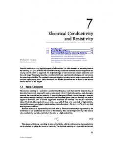
Improving Measurement Performance of EEG Signal Acquisition: An Electrical Aspect for Front-end Ali Bulent Usakli Dept. Technical Sciences, The NCO Academy, Balikesir, Turkey
E-mail:
[email protected], phone +90 266 2212350-4420, fax +90 266 2212358
Abstract. The aim of this study is to present some considerations in acquiring satisfactory signals for electroencephalographic signal acquisition. The electrodes and the initial electronic cicuitry front-end, plays an important role in improving the system’s measurement performance. Considering the pitfalls in the design of biopotential measurement system and recording sessions, specifically, the initial cicuitry creates better accuracy. In electroencephalogram (EEG) recording; electrodes, electronic circuitry including filtering, amplifying, signal conversion, data storing, and enviromental recording conditions affect the recording performance. In this paper, electrodes and electronic noise reduction methods in EEG signal acquisition front-end are explained, and some sugestions are presented. Keywords: EEG; EEG Front-End; Electronic Noise Reduction; EEG Signal Acquisition Improvement;
1. Introduction The human brain generates electrical signals called electroencephalograms (EEG) which are related to body functions. These signals are roughly less than 100 µV and 100 Hz and can be measured with electrodes placed on the scalp. Because of their low amplitude due to the skull’s composition, the measurement of EEG is more difficult than the other noninvasive biosignal measurements such as the electrocardiogram, electromyogram and electrooculogram, etc. In that sense, some factors to acquire good EEG signals should be considered in new designs and during recording sessions. These major considerations are discussed and some suggestions are presented in this paper. In biosignal recordings, electrodes are the initial elements which are used for converting biopotential signals due to biopotential sources into electrical signals. Figure 1 shows the simplified biopotential measurement. EEG electrodes are usually made of metal, and are produced as cup-shaped, disc, needle or microelectrode to measure intra-cortex potentials. Silver chloride (AgCl), is preferred for common neurophysiologic applications [1]. Because Ag is a slightly soluble salt, AgCl quickly saturates and comes to equilibrium. Therefore, Ag is a good metal for metallic skin-surface electrodes [2]. Choosing the correct electrode as well as preparation of the skin before recording affects the accuracy of the measurements. Another major factor is electronic noise which is quite important for the biosignal measurements. Electronic noise can be caused by both internal and external noise sources. The internal noise sources are thermal (due to resistive components), shot (due to semiconductor holes and diffusions), flicker (due to contact pins) and burst (popcorn, due to impurities in semiconductors) noises [3]. The most important external noise is caused by power line interference. It is clearly seen in spectral analysis at 50 Hz (or 60 Hz). Between power lines and the subject there are capacitances (parasitic and isolation). To extract biosignals precisely from electronic noise requires efficient noise reduction methods [3, 4]. Efficient analog and/or digital filtering is needed for this purpose. In the following sections EEG electrodes, EEG recording and design considerations are presented.
Figure 1. Biopotential measurement via electrodes.
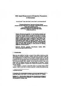
2. Materials And Methods 2.1. EEG Electrodes Electrodes may be polarized (non-reversible) or non-polarized (reversible). Polarization is avoided since the chloride ion is common to both the electrode and the electrolyte. Other metals such as gold or platinum can be used for electrode fabricating, but are costly. Polarized electrodes tend to make significant capacitance, and this may interfere with the transmission of underlying biosignals. These electrodes behave like a low-frequency filter (lowpass filter). Non-polarized electrodes, such as those of AgCl, are preferred for common neurophysiologic applications [1,2]. Normal Ag/AgCl electrodes need to be chlorinated in time, however, sintered Ag/AgCl electrodes do not need to be chlorinated. The EEG electrodes can be classified as: disposable; reusable disc and cup shaped (EEG caps); sub-dermal needles (single-use needles that are placed under the skin) and implanted electrodes (to precise pinpoint the origin of seizure activity). Needles are available with permanently attached wire leads, where the whole assembly is discarded, or sockets that are attached to lead wires with matching plugs. They are made of stainless steel or platinum. Some of EEG electrodes can be used for special applications. For example, implanted EEG electrodes also can be used to stimulate the brain and map cortical and sub-cortical neurological functions, such as motor or language function, in preparation for epilepsy surgery. Infection must be considered as a major risk of implanted EEG electrodes. In a non-invasive electrical brain signal measurement, there is an interface material between the electrode and the skin. This material is an electrolyte and can be in EEG gel or paste form. The electrophysiological activity caused by a biopotential source is a current source that causes current flow in the extracellular fluid and other conductive paths through the tissue. A cup-shaped electrode provides enough volume to contain an electrolyte, including chlorine ions. In these electrodes, the skin never touches the electrode material directly. The electrode-tissue interface has impedance depending on several factors. Some of these factors are the interface layer (such as skin preparation, fat mass, hair, etc), area of electrode’s surface, and temperature of the electrolyte. The electrode-tissue contact can be modelled as in Figure 2. As it is seen from the figure, the electrode-tissue interface is not only resistive but consists of capacitive elements too. This is important for the frequency dependency of the electrode-skin contact. Because of the interaction between metallic electrode and electrolyte, the ions accumulated as parallel plates. Ion-electron exchange occurs between the electrode and the electrolyte. This exchange results in voltage and it is called the half-cell potential. Because of this potential, in some cases, biopotential amplifiers must tolerate up to ± 300 mV. This value depends on the electrode and electrolyte material. This can be explained by the Nernst Equation, simply: 0,05916 (1) ε ε0 logQ ne Here, : Half-cell potential (V), ne: Transported electron (mol number), Q: Rate of ions ( Q Ions Inside ).
Ions Outside
Figure 2. Simplified equivalent circuit of biopotential source and electrode-tissue interface from electrode. Biopotential source as a current source and tissue resistance is shown Rt. Cet and Ret electrode-tissue equivalent elements and may change for each electrode contact.
In clinical EEG recordings, 10/20 Electrode Placement System has been a standard, and in general, it has been used for many clinical or research applications [5]. Although there are 75 locations in this system, 8 to 32 electrodes may be sufficient for clinical applications. 8 channels can also be sufficient for some Brain Computer Interface (BCI) applications; on the other hand, for Electrical Source Imaging (ESI) more than 100 channels are required. Because of the requirements, another placement system is 5% electrode placement and 345 locations are determined [6], but it has not been a common standard. 2.2. EEG Recordings In EEG system, as a non-invasive application, the electrodes are placed on the scalp, and a sufficient number of electrodes may be 1 to 256 (or more in near future) placed on EEG cap for easy application. To provide ionic current and to reduce contact impedance between the electrode surface and the scalp, EEG gel or paste must be used together for proper skin preparation. In biopotential measurements, the most important point is preserving the biosignal’s originality. The contact impedance should be between 1 kΩ to 10 kΩ to record an accurate signal. Less than 1 kΩ contact impedance indicates a possible short-cut between electrodes, on the other hand, impedance greater than 10 kΩ can cause distorting artefacts. Drying the gel or paste in time, subject perspiration and movements (eye blinks, muscle movements, heart beats, etc) can easily affect the measurement performance negatively. Because of these reasons, recording time is generally limited for several hours. For long periods of time or ambulatory EEG recordings, additional requirements are necessary to make patients more comfortable and to allow consistent system performance. High resolution applications such as ESI or wireless data transfer also require a different approach for the design of the novel electrodes. To reduce the skin preparation time and to measure the biosignals more accurately, several approaches are attempted for electrode fabrication. For example multi-array thin film electrodes are developed especially for different depth in operational applications [7]; nitride covered steel is used as an electrode and there is no need for EEG paste and successful recordings are acquired [8]. In the last few years, active electrode (small or unity gain amplifier close to electrode) research is gaining popularity. With these types of electrodes, without electrode gel and much more skin preparation, noise reductions are reported [9-12]. In commercial applications, apart from classical cup- or disc-shaped electrodes and active electrodes, another approach is used to reduce preparation time (by EGI's HydroCel Geodesic Sensor Net). In this approach, scalp preparation and abrasion are not required. Because the soft pedestal design of the chamber creates a sealed environment, it hydrates the skin and creates an interface between the skin and electrode. Application times for the sponge-based HydroCel Geodesic Sensor Net range between 5 minutes for 32 channels to 15 minutes for 256 channels are reported [13]. In practical consideration at least 45 minutes is required for the electrode while skin preparations for 256 channel cup-shaped electrode cap, 15 minutes is reasonable. Figure 3 shows some EEG electrodes and caps commercially available. In this figure as several examples non-invasive electrodes and EEG caps, and one intra-cortical electrode array are shown.
(a) Ag-AgCl electrodes
(b) Active electrodes
(c) Intra-cortical electrode array
(d) EEG caps (left to right: Standard: 256-ch., (me) (Neuroscan)[14], (Neuroscan)[14], (EGI) [13], Active; (Biosemi) [12], Hydrocel (EGI)[13]. Figure 3. Commercially available EEG electrodes and cap samples, (c) is for invasive applications.
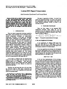
Another approach for fabricating EEG electrodes is dry electrodes (Figure 4). This type of electrode does not need an extensive set-up time, and it is convenient for long-term recordings. These properties are advantageous for BCI and neurofeedback applications. In order to design dry electrodes, 1.5 mm thick silicone conductive rubber shaped discs of 8 mm diameter are used. The active side of the electrode is capacitive coupled through a layer of insulating silicon rubber with a metal shield wired to the active guard shield. The impedance of the realized electrodes at 100 Hz is greater than 20 MΩ with a parasitic capacitance smaller than 2 pF [15]. For under cortex applications intra-cortical electrodes are used. One of these types of electrodes (The Utah Intracortical Electrode Array) is an array of 100 penetrating silicon microelectrodes designed to electrically focus stimulation or record neurons residing in a single layer up to 1.5 mm beneath the surface of the cerebral cortex [16]. Each electrode of the intra-cortical array electrode is 1.5 mm long, 0.08 mm wide at the base and 0.001 mm at the tip. Each type of electrode should be used with a successful electronic circuit. In Figure 5 EEG electrode and initial signal acquisition examples are shown. Recording environment conditions, contact impedance value and its stability, amplification method (ac or dc), and recording time must be considered. In the next sub-section design considerations are explained, briefly. 2.3. The Design Considerations In EEG recordings, as the other biosignal measurements, one of the major problems is the 50 (or 60) Hz noise due to power lines. Between power lines and the subject there are capacitances (parasitic and isolation). Electromagnetic interference (EMI) ways are shown in Figure 6. The environmental factors influence the subject and measurement system. For example, a fluorescent lamp 1-2 m away from the measurement system interferes with the measuring signal as several kHz peaks. The interference signal may be half of the power line (50/60 Hz) noise. In the same way, other electrical or electronic devices may interfere with the biosignal measurements. The dc component of the common mode signal is about several thousand volts and the ac component may be about 1 V. This value may be in mV scale when the subject’s body is grounded with earth ground and may be as high as 20 V when power line is held [17]. Electro-static discharge (ESD) and defibrillator should be considered in electronic design. Protection for this must be provided for initial active components. To reduce common mode signal effects, the instrumentation amplifiers having higher common mode rejection ratio (CMRR) must be used [18,19]. Some research studies related to biopotential design report that 80-136 dB CMRR are obtained [20-22]. To reduce isolation capacitance effects, battery powered operation is efficient [12]. In order to guarantee the subject/patient safety, leakage current should be less than the levels determined by IEC 601-1. According to this regulation, leakage current must be less than 10 µA in normal conditions while regarding the connection to the main power supply, 50 µA is allowable.
Insulator rubber
Cable
Electrode shield Conductive rubber Coaxial cable
Figure 4. A dry electrode principle.
Conductive plate
Rs
Conditioned signal output
Zin Rs
Electrode
Buffered output
Dielectric
Gel or paste Scalp
(a) A cup-shaped electrode.
Scalp
(b) Principle of capacitive electrode.
(c) Driven guard and shielding with metal plates to reduce electromagnetic interferences. Figure 5. EEG electrode connections.
Power line
220 nA 3 pF
220V/50Hz
Magnetic field
IV < 1 pF II
I
+ _ III
Signal output
< 1 pF 300 pF Earth ground Figure 6. Electromagnetic interference (EMI) ways (for the capacitance values [12]). Arrows show the induced currents. (I) Voltage due to magnetic field to electrode cable loop. (II) Displacement current on subject head due to electrical field causes voltage drop across electrodes. (III) Displacement current on subject body due to electrical field causes voltage drop across electrodes. (IV) Additionally, this current causes voltage between measurement electrode and amplifier common pin.
Figure 7. Suggested initial electronic circuitry.
The initial electronic circuit is presented in Figure 7. It can be used wired electrodes (classical approach) or close to electrodes (active electrode approach). After the tests, it is observed that the circuit can be used for EEG, EOG or EMG signal measurements. This amplifier cicuit’s gain is 16, and it does not cause biopotential amplifier saturation. Its CMRR is 88 dB under no shielding conditions and EMI protections.
3. Conclusion There are major points that should be considered in the design of the biosignal measurement system or recording session to improve measurement performance. Specifically choosing the correct electrode, skin preparation, and power line noise are the important issues for EEG recordings. To reduce electromagnetic interferences, a metal box should be used for electronic circuits as well as a shielded (Faraday cage principle)
recording room, and guarding (driven or not) for common mode signal reduction are the efficient methods. The major points that I briefly proposed for the entire recording process are: providing subject/patient safety (leakage current, and defibrillator protection if it is necessary), EMI protection (operation of electrical or electronic devices, and fluorescent lamps around recording set-up is prohibited), no subject/patient muscular movements, isolation of subject/patient-front-end circuitry and earth grounds (analog and digital grounds), ESD protection (>2000 V), Efficient grounding technique (metal cases must be connected to metal plate/rod buried under ground), proper electrode contact impedance (between 1 kΩ and 10 kΩ for classical electrodes), noise immunity (electronic circuit and printed circuit board design, and placed metal box to reduce electronic noise as much as possible (< 2 µV) sufficient reduction for common mode signals (>80dB CMRR), preserving the biosignal originality, avoiding amplifier saturation, high cross-talk rejection between channels, sufficient input impedance (>1GΩ), low input bias current, sufficient isolation impedance, acquiring as much of the biosignal signal as possible, selecting the proper filter band (at least band width 0,5 Hz-70 Hz) and pole, removing dc level, environmental temperature independent performance, sufficient (and optimum) digital resolution (>12 bits for ac amplification, >20 bits for dc amplification), biopotential amplifier linearity, no delay between channel sampling instants, sufficient (and optimun) sampling rate (>140 Hz), and transfer rate, sufficient (and optimum) recording time (otherwise drying gel, creating anxiety in subject/patient, and insufficient data collection time due to short recording times from unsuccesful signal acquisition), placement in metal box for shielding, and/or shielded recording envioriment, user friendly interface, low power consumption and low cost. The performance of the biosignal measurement system depends on the electrodes, electronic circuitry, and recording conditions. Choosing the correct electrode and succesful front-end design are essential to acquire good signals.
References [1] [2] [3] [4] [5] [6] [7] [8]
C. M. Sinclair, M. C. Gasper, A. S. Blum. Basic Electronics in Clinical Neurophysiology, The Clinical Neurophysiology Primer, ed: A. S. Blum, S. B. Rutkove, New Jersey: Humana Press, 3-18, 2007. D. Prutchi, M.Norris. Design and Develeopment of Medical Electronic Instrumentation, New Jersey: Wiley, 5-14, 2005. W. Leach. Fundamentals of low-noise analog circuit design, Proceedings of The IEEE, 82 (109: 1515-1538, 1994. H.W. Ott. Noise Reduction Techniques in Electronic Systems”, Second Edition, John Wiley & Sons, New York, 359-361, 1988. H.H. Jasper. The ten–twenty electrode system of the international federation, Electroencephalogr. Clin. Neurophysiol. 10: 367–380, 1958. R. Oostenveld, P. Praamstra. The five percent electrode system for high-Resolution EEG and ERP measurements, Clinical Neurophysiology, 112 (4): 713-719, 2001. O.J. Prohaska, F. Olcaytug, P. Pfundner, H. Dragaun. Thin-film multiple electrode probes: possibilities and limitations. IEEE Trans. Biomedical Eng. BME-33, 223–229, 1986. B.A. Taheri, R.T. Knight, R.L. Smith. A dry electrode for EEG recording, Electroencephalography and Clinical Neurophysiology, 90 (5), 376-383, 1994.
[9] [10]
[11] [12] [13] [14] [15] [16] [17] [18] [19] [20] [21] [22]
W.J.R. Dunseath, E. F. Kelly. Multichannel PC-based data-acquisition system for high-resolution EEG, IEEE Transactions on Biomedical Engineering, 42 (12): 1212-1217, 1995. A.C. MettingVanRijn, A. P. Kuiper, T. E. Dankers, C. A. Grimbergen. Low-cost active electrode improves the resolution in biopotential recordings, Proc. of the 18th Annual International Conference of the IEEE Engineering in Medicine and Biology Society, Amsterdam, 1- 3, 1996. G. A Litscher. Multifunctional helmet for noninvasive neuromonitoring, Journal of Neurosurgical Anesthesiology, 10 (2): 116-119, 1998. Egi. Product catalog, 2009, http://egi.com/research-division-research-products/sensor-nets Neuroscan. Product catalog, 2009, http://www.neuroscan.com/quick_caps.cfm Biosemi. Product catalog, 2009, http://www.biosemi.com/active_electrode.htm G. Gargiulo, P. Bifulco, R.A. Calvo, M. Cesarelli, C. Jin, A. van Schaik. A mobile EEG system with dry electrodes, IEEE Biomedical Circuits and Systems Conference Biocas, Baltimore, 20-22, 2008. P.J. Rousche, R.A. Normann. Chronic recording capability of the Utah Intracortical Electrode Array in cat sensory cortex Journal of Neuroscience Methods, 82 (1): 1-15, 1998. B.B. Winter, J.G. Webster. Reduction of interference due to common mode voltage in biopotential amplifiers, IEEE Trans. on Biomedical Engineering, 30 (1): 58-66, 1983. R. Aston. Principles of Biomedical Instrumentation and Measurement, Ohio: Prentice Hall, 222-256, 1990. J.G. Webster. Medical Instrumentation, Application and Design, 2nd Edition, Boston: Houghton Mifflin, 184-204, 1992. G. Litscher. A Multifunctional Helmet for Noninvasive Neuromonitoring, Journal of Neurosurgical Anesthesiology, 10 (2): 116-119, 1998. Ulbert, E. Halgren, G, Heit, G. Karmos. Multiple Microelectrode-recording System for Human Intracortical Applications, Journal of Neuroscience Methods, 106 (1): 69-79, 2001. A.B. Usakli, N.G. Gencer. USB-based 256-channel electroencephalographic data acquisition system for electrical source imaging of the human brain, Instrumentation science & Technology, 35 (3): 255-273, 2007.