Improving Soft Error Correction Capability of 4-D Parity Codes Muhammad Imran
Zaid Al-Ars
Georgi N. Gaydadjiev
Computer Engineering Laboratory Delft University of Technology The Netherlands Email:
[email protected]
Computer Engineering Laboratory Delft University of Technology The Netherlands Email:
[email protected]
Computer Engineering Laboratory Delft University of Technology The Netherlands Email:
[email protected]
Abstract— In order to reduce overall system costs, the aerospace industry has been increasingly using commercial off the shelf components in their products. The sensitivity of these products to radiation induced soft errors becomes a major concern. In this paper, we propose a method to increase the reliability of a given off the shelf component by manipulating the software-based error correction algorithm of its already existing 4-D parity codes. The paper shows that using this approach, it is possible to correct triple bit adjacent errors, without adversely affecting the performance or memory usage. Furthermore, we discuss the results of implementing and validating the proposed approach in practice on PIC microcontrollers.
I. I NTRODUCTION In its short history, space exploration has made extensive use of modern electronics and computerized devices on its missions. The space environment, however, is particularly harsh, as it is characterized by radiation, extreme temperatures and zero pressure. The increased radiation requires using a special kind of Radiation Hardened ICs (RHICs) for space applications. Due to the high cost of RHICs and the limited number of manufacturers, the trend of the space industry has been shifting towards using more Commercial Off The Shelf (COTS) components and enabling them for space applications. COTS components are designed and manufactured according to normal, commercial business practices and are characterized by low cost. COTS components require short development time and, therefore, reduce the overall system cost. Reliability is a major concern when using COTS components in space or military applications. The reliability issue in COTS components can be solved in a number of ways, one of which is the use of Error Detection And Correction (EDAC) schemes. These EDAC schemes can either be implemented in hardware or in software. In this paper, we focus on software implemented EDAC schemes. Section II presents some background information about the space environment and techniques to ensure reliability. In Section III, EDAC codes used in space applications are discussed. Section IV proposes a novel technique which can improve the error correction capability of an already existing EDAC scheme. Experimental results are presented in Section V. Finally, a brief summary and conclusions are given in Section VI.
II. BACKGROUND The successful accomplishment of any space mission depends very much on the correct operation of the electronic equipment installed onboard. Proper operation in space poses various challenges, such as limited power, extreme temperature and most importantly cosmic radiation, which reduces the reliability of electronic components. The main focus of this paper is to mitigate the effects of radiation and ensure the fault-free operation of electronic equipment onboard. A. Radiation Radiation is the process of energy emission in the form of waves or particles. There are various types of radiation depending on the type of the emission source, properties and purposes of the emission, etc. We discuss here the impact of radiation on the normal operation of electronic circuits. Out of many effects produced by ionizing radiation, single event effects and the total ionization dose are two phenomena which occur frequently in space electronics. 1) Single event effects: Single Event Effects (SEEs) are caused by single energetic particles. When these high energy particles strike an electronic circuit, they produce ionization within the semiconductor material of an IC. This ionization causes either transient or permanent errors. Generally, SEEs can be divided into three classes according to their impact on ICs: • Single Event Upset (SEU); • Single Event Latchup (SEL); • Single Event Burnout (SEB). 2) Total ionization dose: Another effect due to the radiation is the Total Ionization Dose (TID). When radiation passes through the semiconductor material, electron-hole pairs are created within the oxide (insulating) layers present in the device. Due to their higher mobility, electrons disappear almost immediately while holes remain trapped. These holes change the gate-to-channel potential in CMOS devices which results in threshold-voltage shifts. Furhtermore, creation of traps due to radiation, increases surface recombination velocity at the interfaces, causing an increase in leakage current. This phenomenon degrades the overall performance of an IC in terms of power consumption and sometimes results in total circuit failure [1].
Out of many effects produced by ionizing radiation, SEUs and the TID are two phenomena which occur frequently in space electronics. There are various techniques to mitigate these effects and redundancy is one of them which improves overall system reliability. Different forms of redundancy are briefly discussed here. B. Redundancy in computing systems Redundancy can be defined as the addition of resources, information or time to the system beyond what is needed for normal operating conditions [2]. In the past, duplication of components was considered the only form of redundancy. Today, redundancy can manifest itself in several forms like hardware redundancy, software redundancy, time redundancy and information redundancy. Any one of these four forms of redundancy can be implemented in order to maintain or improve the system reliability. Hardware redundancy is implemented by replicating the hardware modules. This does not only increase the cost of the electronic subsystem, but also the mass and power budget. Software redundancy involves writing extra lines of code in software to verify the correctness of a given signal. Whereas, in time redundancy, fault tolerance is achieved at the expense of extra time. Information redundancy requires extra information. Information redundancy is mainly implemented by EDAC codes. The use of EDAC codes for space applications has been in practice for last four decades. In this paper, we restrict ourselves to EDAC codes as a good alternative to improve the system reliability. EDAC codes used in space applications are briefly discussed in Section III. III. E RROR
DETECTION
&
CORRECTION CODES
There are various types of error correcting codes available, but we will discuss here only those which have been previously implemented in space applications. Some general concepts and several basic terms are discussed here for error detection and correction codes. If we have n bits, there are 2n unique codewords that can be constructed. Similarly k data bits can take 2k different forms. If k < n, then the remaining n − k bits can be used as redundant bits or parity bits in the codeword. These parity bits contribute towards the error detection and correction property of any code. The terms parity bits, check bits or redundant bits are used interchangeably for the same concept in error coding literature. We will use the term parity bits for these and represent them by notation c, throughout our paper. The number of data bits in the codeword determines the code rate, which can be defined as, the measure of relative amount of information which is transmitted in each codeword [3]. Code Rate = R =
Data bits k = Total number of bits n
(1)
where k are data bits and n is total number of bits in the codeword. Another important measure to compare the two codes is the bit overhead. The Bit Overhead (BO) can be defined as, the
ratio of parity bits to data bits. Bit overhead determines the percentage of redundancy in the codeword. c Parity bits = (2) Data bits k If we have two n-bit binary codewords where a = a1 a2 ...an and b = b1 b2 ...bn , The Hamming Distance dh , between a and b is defined as the minimum number of bits in which a and b differ from each other [3]. Bit Overhead = BO =
A. Hardware vs software EDAC implementation EDAC codes play an important role in mitigating the impact caused by SEUs and hence improve system reliability. These EDAC codes are usually implemented in hardware, but require an extended memory bus architecture to accommodate parity bits and additional encoding/decoding circuitry. In low-cost projects, system can be designed using COTS components which do not support built-in EDAC schemes. EDAC codes can also be implemented in software. Data is encoded using these EDAC codes and resulting parity bits are stored. These parity bits are periodically checked to detect and correct the soft errors caused by radiation. Throughout this paper, we will assume any EDAC code on data memory of size (m x k) 32 x 16 bits. B. Types of EDAC codes Various types of EDAC codes are used in computers, communication systems and in space applications. Here we will describe a few of software implemented EDAC codes to protect the onboard memory from radiation. The codes used in space applications are as follows: • Hamming codes; • Parity codes; • Rectangular parity codes; • Three-dimensional parity codes; • Four-dimensional parity codes; • Golay codes; • BCH codes. Hamming (12,8,3) is Single Error Correction (SEC) code which can correct single errors in each codeword of the block. Parity codes can have Single Error Detection (SED) property in each codeword of the memory array. Rectangular parity codes operate on a whole block and have capability to make single error correction anywhere in the whole block instead of single codeword. Four-Dimensional (4-D) parity codes are also applied on a whole block of data instead of individual codewords. They have Double Error Correction (DEC) capability. Golay and BCH codes are examples of cyclic codes. Both of these codes have Triple Error Correction (TEC) capability and they operate on a single codeword. C. Space & time complexity of EDAC codes All the above discussed software implemented EDAC codes are summarized in Table I. We present here the bit overhead, code rate, space and time complexity and error detection &
TABLE I
bit error is shown in Figure 1(b) to make a fair comparison between the two. If we compare the row, column and diagonal
C OMPARISON OF EDAC CODES . Error Correcting Code Hamming(12,8,3) Parity Rectangular parity 4-D parity Golay(23,12,7) BCH(31,16,7)
Bit Overhead
Code Rate
50.00% 6.25% 12.50% 18.75% 91.67% 93.75%
66.67% 94.12% 91.43% 84.21% 52.17% 51.61%
Complexity Time Space O(mn) O(mn) O(mn) O(mn) O(mk) O(k 2 )
O(mn) O(mn) O(mn) O(mn) O(2k ) O(mn)
Error Correction Capability SEC SED SEC DEC TEC TEC
correction capability of each code. All mentioned codes except Golay and BCH codes have linear time and space complexity. Golay codes implement look up tables requiring exponential space complexity. Look up tables dramatically reduce the time complexity of Golay codes and they require linear time. BCH codes which implement Galois fields require quadratic time complexity and linear space complexity. In the next section, we discuss a novel approach which can improve the error correction capability of already existing 4-D parity codes. IV. I MPROVING
THE RELIABILITY OF
4-D
PARITY CODES
This section presents a novel approach which improves the error correction capability of already existing 4-D parity codes. It also helps to mitigate the multiple-bit errors caused by radiation. We conclude this section by comparing proposed 4-D parity codes with other triple error correcting codes. A. Novel approach for error detection and correction Multiple Bit Upsets (MBUs) potentially pose more threat to system reliability than SEUs because certain EDAC codes, such as the Hamming code, are not able to correct more than one error in the same word [4], [6]. MBUs can be corrected through multiple-bit error correction codes, a few of them were discussed in Section III. These EDAC codes, for multiple bit error correction require large memory area and more time for their implementation as compared to single error correction codes. We need to investigate some ways by which the error correction capability of a code can be improved with minimal overhead in space & computational activity.
1
0
0
0
1
1 1 1
1
0
0
1
0
1
1
1
0
0
1
0
1
1
0
1
1
0
0
1
0
1
1 1
0 0
0 0
1 1
1 0
1 1
0 1
1 1
0 1
0 0
1 1
0 1
1 0
1 0
1
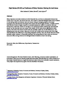
B. Innocent bit definition Here, we introduce the concept of ”innocent bit” in four-dimensional parity codes. In case of an innocent bit, horizontal and vertical parity check lines point to data bit in error which is actually not erroneous. This results when three adjacent bits are in error as illustrated in Figure 1(a). Single
0
0
1
0
1
1 1 1
1
0
0
1
0
1
1
1
0
0
1
0
1
1
0
1
0
1
1
1
0
1
1 1
0 0
0 0
0 1
0 0
1 1
0 1
1 1
0 1
0 0
1 1
0 1
1 0
1 0
1
(a) Fig. 1.
1
(b)
(a) Triple bit error (innocent bit) (b) Single bit error
parity indication of the innocent bit (h = v = d = 1) and the single bit error case (h = v = d = 1), we can note that the single error indication in row, column and diagonal in both cases. Here h, v and d represents horizontal, vertical and diagonal number of bits in error, respectively. Careful observation shows here that diagonal bit error indication in case of innocent bit (d1 6= h1 + v1 ) is not similar to the single bit error case, where d1 , h1 and v1 show the occurrence of first erroneous bit in diagonal, horizontal and vertical lines, respectively. In general for single bit errors, we have (d1 = h1 + v1 ) and intersection of row, column and diagonal point to the same bit position in error. But in Figure 1(a), intersection of row, column and diagonal does not point to same bit position. So we can observe that when (h = v = d = 1 and d1 6= h1 + v1 ), it is not a single bit error. 1
0
0
1
0
1
1 0 1
1
0
0
1
0
1
1
1
0
0
1
0
1
1
0
1
1
1
1
1
0
1
1 1
0 0
1 1
1 0
0 0
1 1
0 1
1 1
0 1
0 0
1 1
0 1
1 0
1 0
1
(a)
Here we present a novel approach, which can improve the error correction capability of already existing 4-D parity codes. Using this novel approach, we can correct three adjacent errors instead of two without seriously affecting the performance. Most importantly, this improvement does not incur any extra parity bits in the code, meaning the same code rate and bit overhead is required to correct three adjacent incorrect bits.
1
Fig. 2.
1
0
1
0
1
1 1 1
1
0
0
1
0
1
1
1
0
0
1
0
1
1
0
1
0
1
1
1
0
1
1 1
0 0
0 0
0 1
0 0
1 1
0 1
1 1
0 1
0 0
1 1
0 1
1 0
1 0
1
1
(b)
(a) Triple bit error, innocent bit (b) Single bit error
We confirm our observation by another example which is illustrated in Figure 2. First part of the figure shows an innocent bit but this time the three errors are occurring at different positions. These all three errors mock up to innocent bit pointing to the same bit position indicated in Figure 1(a). In this case too, we have h = v = d = 1 but d1 6= h1 + v1 . Up till now, we can detect innocent bit errors whether it is due to three errors at the top-right position of the innocent bit or at the bottom left position of it. But the innocent bit can also manifest itself in the form where d2 = h1 + v1 . This is shown in Figure 3. In this case, row, column and
0
1
1
0
1
0
1
0 1 1
1
0
0
1
0
1
1
1
0
0
1
0
1
1
0
1
1
0
1
1
0
1
1 1
0 0
1 0
1 1
0 0
1 1
0 1
1 1
0 1
0 0
1 1
0 1
1 0
1 0
1
(a) Fig. 3.
1
1
0
1
0 1 1
1
0
0
1
0
1
1
1
0
0
1
0
1
1
0
1
0
1
1
1
0
1
1 1
0 0
0 0
1 0
1 1
1 1
0 1
1 1
0 1
0 0
1 1
0 1
1 0
1 0
1
1
(b) Examples of innocent bit (Triple-bit error).
diagonal parity check lines intersect at the same bit position but in reality that bit is not in error. We can note here that instead of d1 = h1 + v1 we have d2 = h1 + v1 . Moreover, instead of single diagonal parity bit in error, we have three diagonal parity bits in error (h = 1, v = 1, but d = 3). This is clearly different from the single error bit because in single error bit case we have h = v = d = 1 and d1 = h1 +v1 .
occurrence of innocent bit regardless of the way three error bits orientate themselves. We can correct the triple bit errors as shown in Figure 1 and 2. This can be done by examining the diagonal bits. If we have (h = v = d = 1 and d1 6= h1 + v1 ) and d1 − 2 = 1, we can confirm that the three bits in error are at the top-right position of the innocent bit as shown in Figure 1(a). Similarly, if we have (h = v = d = 1 and d1 6= h1 + v1 ) and d1 + 2 = 1, we are sure that this time the three bits in error are at the bottom-left position of the innocent bit as shown in Figure 2(a). At the moment, we can only detect if triple bit errors occur as shown in Figure 3. It is not possible to correct these triple bit errors without extra parity bits. The pseudocode given above is only for their detection, which will of course improve the reliability by signaling the erroneous situation and not detecting and correcting it as a single bit error. C. Triple bit error correction
It is mentioned in the Section III that 4-D parity codes can correct a maximum of two errors. Putting some additional computations and comparisons in the code, we can correct, not all but most of triple bit errors. Triple bit errors can In light of the discussion above, we propose here a novel be classified in two categories, adjacent errors and scattered strategy which can differentiate between single and triple bit errors. We are more interested in adjacent errors because they errors. If row, column and diagonal parity check bits point are expected to occur more frequently due to multiple bit to the same location, checking neighboring diagonal bits will upsets. Each of them is discussed as follows. differentiate between single and triple bit errors. This is best 1) Adjacent errors: Detection and correction of the inexplained in the code given here. nocent bit is one type of adjacent errors that can occur in onboard memories. Triple bit adjacent errors can also manifest Calculate horizontal, vertical and diagonal themselves in the single row, column or in diagonal. We parity bits, compare these to stored parity propose here another strategy by which we can correct any bits using XOR operation. Calculate the three adjacent errors occurring in the same row, column or no. of bits differing in each parity line; diagonal. All these three possibilities are shown in Figure 4. if(h=v=d=1){ if (d1=h1+v1){ 0 0 1 0 1 1 0 0 1 0 1 1 0 1 0 0 1 1 Single bit error; 1 1 0 0 1 0 1 1 0 1 0 0 1 0 1 1 1 1 0 0 1 0 1 1 } 1 1 1 0 1 0 1 0 0 1 0 0 1 0 1 1 1 1 0 0 1 0 1 1 if (d1 != h1+v1){ 1 1 1 0 1 1 1 1 1 1 0 1 1 1 1 1 1 0 1 1 0 0 1 1 1 1 0 0 0 0 1 0 1 1 0 1 1 0 1 0 Triple bit error; 1 1 0 0 1 0 1 1 1 1 0 0 1 0 1 1 1 1 0 1 1 0 1 0 1 1 0 0 1 0 1 1 } 1 0 0 1 0 1 1 1 0 0 1 0 1 1 1 0 0 1 0 1 1 } 1 0 1 1 1 0 0 1 1 1 0 1 0 0 1 1 1 1 0 0 0 if(h=v=1 AND d=3 AND d2=h1+v1){ (b) (c) (a) Triple bit error; } Fig. 4. Triple bit adjacent errors in same (a) row, (b) column and (c) diagonal
In the pseudocode above, we first determine the number of errors in each of horizontal, vertical and diagonal parity bits. If single error occurs in each of these parity check lines and bit position of diagonal parity bit is the sum of horizontal and vertical parity bit positions (d1 = h1 + v1 ), there is single error, otherwise triple bit error has occurred. In other case, if horizontal and vertical parity bits show single error and diagonal parity bits show 3 errors, we check if the bit position of second diagonal parity bit is the sum of horizontal and vertical parity bit positions (d2 = h1 + v1 ). If the condition is true, triple bit error has occurred. Here an important point to note is that we can detect the
The strategy is that if we observe a single error in row parity line (h = 1) and triple error in column (v = 3) and diagonal parity line (d = 3), we are sure that three bits in the same row are in error. Although row parity line is showing a single bit error but due to modulo 2 sum (3 mod 2 = 1), we can observe only a single error in the row parity. Column parity bits and diagonal parity bits confirm this triple bit error by showing three errors in each of them. While implementing the code for correcting errors, we shall use the row address three times with each of the column and diagonal bits (d1 = h1 + v1 , d2 = h1 + v2 and d3 = h1 + v3 ).
Using this strategy, we can detect and correct any odd number of errors. But this will lead to a large number of comparisons so here for the sake of simplicity, we restrict ourselves to only three errors. Similarly, if three error bits occur in a column, then row and diagonal parity bits will show three errors but column parity bits will show only a single bit error (v = 1, d = h = 3). Using the same approach described above, we can also correct triple bit errors in a diagonal (h = v = 3, d = 1). 2) Scattered errors: All double bit scattered errors can be corrected using 4-D parity codes [5]. But all triple bit scattered errors cannot be corrected using this approach. We can only correct a few scattered errors using 4-D parity codes. This is shown in Figure 5. In simple words, if each of the three errors occur in a unique row, column and diagonal, only those scattered errors can be corrected using 4-D parity codes.
TABLE II S UMMARY OF 4-D PARITY CODES Sr. No 1 2 3 4
5
6
0 1 0 1 1 1
0
0
0
0
1
1
1
0
0
1
0
1
1
1
0
0
0
0
1
0
0
1
1
1
1
1
1
1 1
1 0
0 0
1 1
0 0
1 1
0 1
1 1
0 0
0 1
1 1
0 1
1 0
1 0
1
1
1
1
1 1 1
1
1
0
1
0
1
0
1
0
0
1
1
1
0
0
1
1
1
1
1
1
1
1 1
0 0
0 0
1 1
0 0
1 1
1 1
1 1
0 0
0 1
1 0
0 0
1 0
1 0
1
(b)
(a)
Fig. 5.
1
(a) & (b) Triple bit scattered errors
D. Analysis of the proposed scheme We have proposed a novel scheme which can improve the error detection and correction capability of already existing 4-D parity codes. The summary of our proposed strategy is given in Table II. In Table II, Row 1 shows the number and bit positions affected when single error occurs. The necessary condition for this case is that the position of diagonal parity bit should be the sum of horizontal and vertical parity bit positions. If this condition is not satisfied, then it represents an innocent bit error which is shown in the next row of the table. In double bit scattered errors, each of three parity check lines will show double errors. For double bit adjacent errors, any two out of three parity lines will show double errors. For example, if there are two adjacent errors in the same row, then corresponding horizontal parity bit will not show an error but vertical and diagonal parity bits will show double errors. We have already discussed in detail triple bit adjacent and scattered errors. Here, an important thing to note is that we have not considered the system parity bit in our modified 4-D scheme. Taking into account system parity bit in our code will increase the number of comparisons and its complexity. We assume that the probability of error in parity bits (horizontal, vertical and diagonal parity bits) is less in comparison to data bits and ignoring system parity bit will have negligible effect on performance.
Type of Error
Single bit error d1 ≡ h1 + v1 Innocent bit error (a) d1 6= h1 + v1 (b) d2 ≡ h1 + v1 Double bit errors scattered Double bit adjacent errors (a) same row (b) same column (c) same diagonal Triple bit adjacent errors (a) same row (b) same column (c) same diagonal Triple bit scattered errors Only if (d1 ≡ h1 + v1 ) AND (d2 ≡ h2 + v2 ) AND (d3 ≡ h3 + v3 )
Row parity check h1
Column parity check v1
Diagonal parity check d1
h1 h1 h1 h2
v1 v1 v1 v2
d1 d1 d2 d3 d1 d2
0 h1 h2 h1 h2
v1 v2 0 v1 v2
d1 d2 d1 d2 0
h1 h1 h2 h3 h1 h2 h3
v1 v2 v3 v1 v1 v2 v3
d1 d2 d3 d1 d2 d3 d1
h1 h2 h3
v1 v2 v3
d1 d2 d3
Now the question is: what is the price we have to pay in order to correct three bits in error. The answer is that we just need some extra comparisons which require constant time. The time overhead is not significant so the total time required to implement the proposed technique on a given set of data remains linear O(mn). So our claim is valid that using the same number of redundant bits, we have devised a novel strategy which can correct most of triple bit errors. The code rate and bit overhead are still same. The price has to be paid in terms of a few extra computations which does not adversely affect the overall complexity. We have already stated that 4-D parity codes implementing our approach can not correct all triple bit errors. We have focused here on mitigation of adjacent errors that are caused by multiple bit upsets. Adjacent errors are more important due to their increasing trends [4]. V. E XPERIMENTAL R ESULTS Here we compare the 4-D parity codes implementing our novel approach with other triple bit error correcting codes. This comparison is based on bit overhead, code rate, error correction capability and time & space complexity. This comparison is presented in Table III. We state our comparison TABLE III C OMPARISON OF TRIPLE BIT ERROR CORRECTING CODES . S No. 1 2 3
Error Correcting Code Golay(23,12,7) BCH(31,16,7) 4-D Parity Code
Bit Overhead
Code Rate
91.67% 93.75% 18.75%
52.17% 51.61% 84.21%
Complexity Space O(2k ) O(mn) O(mn)
Time O(mk) O(k 2 ) O(mn)
with BCH (31,16,7) codes because they require less memory for their implementation as compared to Golay (23,12,7)
codes. In Table III, we can clearly observe that for the same error correction capability, proposed 4-D parity codes are better by approximately 75% than BCH(31,16,7) codes in terms of bit overhead for the same memory size. For code rate, proposed 4-D parity codes out-performed BCH(31,16,7) codes by approximately 30%. Proposed 4-D parity scheme requires linear time complexity whereas BCH codes require quadratic time complexity. Golay codes also require linear time complexity but exponential space complexity which is not feasible in low-cost space projects. Hereafter we summarize the advantages and disadvantages of proposed 4-D parity codes. Improved 4-D parity codes have the following advantages: • High code rate; • Low bit overhead; • Linear time & space complexity; • Easy encoding and decoding; • Easily applicable to any size of memory. This scheme has the following disadvantages: • Applicable to block of memory; • Error correction capability/block; • Need to process whole block of data to detect or correct errors. We have indicated here that error correction capability of 4-D parity codes can be improved with a few additional comparisons. This additional overhead does not deteriorate the code performance in terms of spatial and temporal complexity. VI. S UMMARY
AND CONCLUSIONS
In this paper, we considered the use of commercial components in low-cost space projects. Specialized radiation hardened ICs are commonly used in space applications, which substantially increas the cost of space projects. Commercial components can be used as an alternative, but a high level of reliability must be ensured. We briefly discussed various types of redundancy approaches to maintain or improve the reliability of the system. This reliability can be improved by software in cases where hardware redundancy is not feasible. We concluded that software implemented EDAC codes are a good alternative in low-cost space projects. In section III, we discussed commonly used EDAC codes in space applications. In section IV, we presented a novel approach to improve the error correction capability of already existing 4-D parity codes. We investigated that using this approach, we can correct triple bit adjacent errors. The overhead incurred to implement this approach does not adversely affect the performance in terms of time and memory usage. We showed that for the same error correction capability, 4-D parity codes are better by approximately 75% than BCH(31,16,7) codes in terms of bit overhead for the same memory size. For code rate, the proposed 4-D parity codes out-performed BCH(31,16,7) codes by approximately 30%. We applied the proposed 4-D parity codes to PIC microcontrollers to investigate its feasibility in low-cost space
projects. we have investigated that our novel approach can be implemented in subsystem microcontrollers which have very limited memory. The application of modified 4-D parity codes for microcontrollers with bigger memory is obvious. On the basis of our experimental results, we conclude that 4-D parity codes implementing our approach can correct not all but most of triple bit adjacent errors. The error correction capability can be further improved using a modular approach. There is one important remark about the proposed 4-D parity codes. In real world applications, the implementation of the proposed 4-D parity codes is divided in two phases. The first phase deals with calculation of parity bits whenever new data is written in the data memory. So every time new data is written, all parity calculations are performed and the parity bits are updated in the memory. The second phase deals with the periodic checking in order to detect and correct the errors caused by radiation. A software routine periodically computes the parity bits on stored data and compares it to the stored parity bits. If the parity bits calculated by this routine are the same as the stored ones, then there is no error in the data. In other cases, the number of errors in parity bits and their bit positions are used to detect and correct the errors. R EFERENCES [1] Sherra E. Kerns et.al, The Design of Radiation-Hardened ICs for Space: A Compendium of Approaches, 3rd ed. Proceedings of the IEEE, November, 1998, pp. 1470-1509. [2] Barry W. Johnson, Design & analysis of fault tolerant digital systems, Electrical And Computer Engineering, Addison-Wesley Longman Publishing Co., Boston, MA, USA, 1998, ISBN 0-201-07570-9. [3] Miron Abramovici, Melvin A. Breuer and Arthur D. Friedman, Digital systems testing and testable design, IEEE Press, New Jersey, USA, 1990, ISBN 0-7803-1062-4. [4] S. Buchner et.al, Investigation of single-ion multiple-bit upsets in memories on board a space experiment, 47th vol. IEEE transactions on Nuclear Science, June, 2000. [5] Naveen Babu Anne, Utthaman Thirunavukkarasu and Dr. Shahram Latifi, Three and four-dimensional parity-check codes for correction and detection of multiple errors, International Conference on information technology: Coding and computing (ITCC’04), 2004. [6] Philip P. Shirvani, Nirmal R. Saxena and Edward J. McCluskey, Software-Implemented EDAC protection against SEUs, 44th vol. IEEE transactions on reliability, September, 2000.