Article pubs.acs.org/est
Influence of Active Layer and Support Layer Surface Structures on Organic Fouling Propensity of Thin-Film Composite Forward Osmosis Membranes Xinglin Lu,† Laura H. Arias Chavez,‡,§ Santiago Romero-Vargas Castrillón,‡,∥ Jun Ma,*,† and Menachem Elimelech*,‡ †
State Key Laboratory of Urban Water Resource and Environment, Harbin Institute of Technology, Harbin 150090, China Department of Chemical and Environmental Engineering, Yale University, New Haven, Connecticut 06520-8286, United States § Department of Chemical Engineering, Tennessee Tech University, Cookeville, Tennessee 38505, United States ∥ Department of Civil, Environmental, and Geo- Engineering, University of Minnesota, Minneapolis, Minnesota 55455-0116, United States ‡
S Supporting Information *
ABSTRACT: In this study, we investigate the influence of surface structure on the fouling propensity of thin-film composite (TFC) forward osmosis (FO) membranes. Specifically, we compare membranes fabricated through identical procedures except for the use of different solvents (dimethylformamide, DMF and N-methyl-2pyrrolidinone, NMP) during phase separation. FO fouling experiments were carried out with a feed solution containing a model organic foulant. The TFC membranes fabricated using NMP (NMP-TFC) had significantly less flux decline (7.47 ± 0.15%) when compared to the membranes fabricated using DMF (DMF-TFC, 12.70 ± 2.62% flux decline). Water flux was also more easily recovered through physical cleaning for the NMP-TFC membrane. To determine the fundamental cause of these differences in fouling propensity, the active and support layers of the membranes were extensively characterized for physical and chemical characteristics relevant to fouling behavior. Polyamide surface roughness was found to dominate all other investigated factors in determining the fouling propensities of our membranes relative to each other. The high roughness polyamide surface of the DMF-TFC membrane was also rich in larger leaf-like structures, whereas the lower roughness NMP-TFC membrane polyamide layer contained more nodular and smaller features. The support layers of the two membrane types were also characterized for their morphological properties, and the relation between support layer surface structure and polyamide active layer formation was discussed. Taken together, our findings indicate that support layer structure has a significant impact on the fouling propensity of the active layer, and this impact should be considered in the design of support layer structures for TFC membranes.
■
aromatic polyamide active layer intrinsically prone to fouling.2 Consequently, extensive efforts in surface modification of the polyamide active layer have sought to mitigate fouling.14−17 Other studies have shown that the characteristic nanoscale ridge-and-valley structure of the polyamide layer can also exacerbate membrane fouling.18−20 The fabrication of a TFC membrane generally comprises two steps:4 (i) fabrication of a support layer through nonsolvent induced phase separation and (ii) formation of a thin selective layer on the support layer via interfacial polymerization. Previous publications21−24 suggest that the support layer plays a significant role in determining active layer perm-
INTRODUCTION
Membrane processes hold significant promise for addressing the global challenge of water scarcity and the need for greater sustainability.1−3 Highly permeable and selective polyamide thin-film composite (TFC) membranes have facilitated the rise of reverse osmosis (RO) as the dominant technology for desalination.2,4 The ability to separately optimize the two membrane layers (i.e., active and support layers) has also allowed the development of TFC membranes for forward osmosis (FO) and pressure retarded osmosis (PRO).5−7 These technologies have wide potential applications in the water, energy, waste reclamation, agricultural, and biomedical industries.8 Despite the high water permeability and solute selectivity of TFC polyamide membranes, their performance is significantly hampered by fouling.9−13 Intrinsic hydrophobicity and native carboxyl groups, which interact with foulants, make the © 2015 American Chemical Society
Received: Revised: Accepted: Published: 1436
September 8, 2014 November 12, 2014 January 7, 2015 January 7, 2015 DOI: 10.1021/es5044062 Environ. Sci. Technol. 2015, 49, 1436−1444
Article
Environmental Science & Technology
from J.T. Baker (Phillipsburg, NJ) were used for the membrane performance tests and fouling experiments. Unless otherwise specified, all chemicals were dissolved in deionized (DI) water obtained from a Milli-Q ultrapure water purification system (Millipore, Billerica, MA). Sodium alginate (12 to 80 kDa, Sigma-Aldrich, St. Louis, MO), a polysaccharide, was chosen as a model organic foulant. Toluidine blue O (TBO, technical grade, Sigma-Aldrich) was used to characterize carboxyl group density on the TFC membrane surface. Thin-Film Composite Forward Osmosis Membrane Fabrication. Two types of TFC membranes were fabricated. The fabrication protocols were identical except for the choice of solvent (NMP vs DMF) in the phase separation step, which produces the polysulfone support layer. Fabrication details are presented below. The polysulfone support layer was prepared by nonsolvent induced phase separation in accordance with the method described in previous publications.15,24 First, polysulfone beads (12 wt %) were dissolved in a solvent (NMP or DMF), stirred for 8 h, and deaerated in a desiccator for at least 15 h prior to casting. Low-density PET fabric was attached to a clean glass plate (16 × 24 cm) using waterproof adhesive tape. NMP was applied to prewet the PET fabric, and the excess NMP was removed using Kimwipes (Kimberly-Clark, Roswell, GA). A casting knife (Gardco, Pompano Beach, FL), set at a gate height of 10 mils (∼250 μm), was used to spread the polysulfone solution over the wetted PET fabric. The whole composite was immediately immersed in a precipitation bath containing 3 wt % solvent in DI water at room temperature (23 °C) to initiate phase separation. The polysulfone support remained in the precipitation bath for 10 min before being transferred to a DI water bath for storage until polyamide fabrication. The polyamide active layer was formed through interfacial polymerization on the polysulfone support. Supports were first immersed in MPD solution (3.4 wt % in DI water) for 2 min. After the excess MPD was removed from the membrane surface using an air knife, the membrane was immersed in the TMC solution (0.15 wt % in Isopar-G) for 1 min to form the polyamide selective layer on the polysulfone support, followed by vertical draining of excess TMC solution for 2 min. Then, the membrane was cured in a DI water bath at 95 °C for 2 min, immersed in NaOCl solution (0.2 g/L, 2 min) followed by soaking in NaHSO3 solution (1 g/L, 30 s), and cured again in DI water at 95 °C for 2 min. The fabricated TFC membranes were rinsed thoroughly and stored in DI water at 4 °C. Characterization of Membrane Transport Properties. The water permeability, A, salt permeability, B, and salt rejection, R, of pristine TFC membranes were determined in a bench-scale crossflow RO unit. After evaluation under RO conditions, each membrane coupon was characterized in a bench-scale crossflow FO unit for the support layer structural parameter, S. The water permeability of the polysulfone support was also characterized using a dead-end filtration system. The details of these characterization methods can be found in the Supporting Information. FO Fouling Experiments. A bench-scale crossflow FO unit with channel dimensions of 77 × 26 × 3 mm was used in the FO fouling experiments. The experiments were conducted without spacers and under cocurrent crossflow velocities of 8.5 cm/s in both the draw solution and feed solution channels. Solution temperatures were maintained at 25 ± 0.5 °C. All fouling experiments were conducted as follows. First, a clean membrane sample was loaded into the FO cell with the active
selectivity through its presence during active layer formation. Singh et al.21 studied the effect of support layer surface pore size on TFC RO membrane salt rejection and water permeability. Kim et al.22 evaluated the influence of support layer hydrophilicity on membrane perm-selectivity. Ghosh et al.23 investigated the impacts of support membrane structure and chemistry on RO membrane active layer morphology. In addition, Tiraferri et al.24 fabricated different polysulfone supports by varying casting conditions in the phase separation step and evaluated the perm-selectivity of formed TFC FO membranes. Their results also indicated a significant influence of the polysulfone support on the FO membrane active layer transport properties. The above studies suggest a critical role for the support layer in determining active layer perm-selectivity and morphology, with transport properties having received particular attention. It is also known that surface structure, like the intrinsic ridge-andvalley structure of a polyamide thin film, strongly influences membrane fouling propensity.25,26 However, the relative importance of support layer structure in determining polyamide fouling propensity, through its effect on polyamide structure, has not been evaluated. Only Ramon et al.,26 through modeling work, have considered the possibility that the underlying support layer might influence active layer fouling in a significant way. Given the intensity of the current research focus on redesigning support layer structures to maximize transport in FO and PRO, it is of paramount importance to investigate whether these support layer changes might also be contributing to different fouling propensities, which will be highly important for real-world implementation. Knowing the extent to which the support layer surface structure might affect polyamide fouling would also inform efforts to compare polyamide fouling of TFC membranes across RO, FO, and PRO platforms, as these technologies have differently structured support layers.24 In this work, we seek to investigate the influence of support layer surface structure on the fouling propensity of TFC FO membranes. Two types of TFC membranes were fabricated with two different support layers, formed using different solvents for the polymer solution used in the phase separation step. Fouling experiments with a model organic foulant were carried out to compare the fouling propensity of the two TFC FO membranes. Our results indicate that support layer structure significantly impacts the polyamide active layer structure and the organic fouling behavior of the TFC FO membranes. The underlying mechanisms for the difference in fouling behavior are elucidated, and implications for the design of TFC membranes with antifouling properties are discussed.
■
MATERIALS AND METHODS Materials and Chemicals. Polysulfone beads (Mn: 22 000 Da), N-methyl-2-pyrrolidinone (NMP, anhydrous, 99.5%), N,N-dimethylformamide (DMF, anhydrous, 99.8%), 1,3phenylenediamine (MPD, >99%), 1,3,5-benzenetricarbonyl trichloride (TMC, 98%), sodium hypochlorite (NaOCl, reagent grade), and sodium bisulfite (NaHSO3, >99%) were used as received (Sigma-Aldrich, St. Louis, MO). The polysulfone support was cast on a commercial poly(ethylene terephthalate) nonwoven fabric (PET, grade 3249, Ahlstrom, Helsinki, Finland) with a thickness of ∼40 μm. During interfacial polymerization, TMC was dissolved in Isopar-G, a proprietary nonpolar organic solvent (Univar, Redmond, WA). Sodium chloride (NaCl, crystals, ACS reagent) and magnesium chloride (MgCl2·6H2O, crystals, ACS reagent) 1437
DOI: 10.1021/es5044062 Environ. Sci. Technol. 2015, 49, 1436−1444
Article
Environmental Science & Technology
total number of measurements for each membrane type was ∼200. Characterization of Membrane Structural and Material Properties. The surface hydrophilicity of the TFC membranes was evaluated by measuring the contact angle for DI water using the sessile drop method. A 1 μL droplet was placed on the air-dried membrane surface, and contact angles were measured after 10 s (VCA, Optima XE, AST Products, Billerica, MA). For each type of membrane to be characterized, we performed 12 droplet measurements on each of three independently cast membrane coupons. The membrane surface roughness was characterized via multimode atomic force microscopy (AFM, Bruker, Santa Barbara, CA). Imaging of the air-dried samples was performed in tapping mode with silicon probes coated with 30 nm thick back side aluminum (Tap300A, Bruker Nano, Inc., Camarillo, CA). The probe had a spring constant of 40 N/m, resonance frequency of 300 kHz, tip radius of 8 ± 4 nm, and cantilever length of 125 ± 10 μm. Membrane surface morphology was observed through field emission scanning electron microscopy (FE-SEM, SU-70, Hitachi, Japan). Membrane samples were air-dried overnight prior to the measurements and sputter-coated (DESK V, Denton Vacuum, LLC, Moorestown, NJ) with a 10 nm thick layer of chromium. Micrographs of support layer surfaces were quantitatively analyzed for porosity and selected pore metrics using ImageJ 1.46r software (National Institutes of Health, Bethesda, Maryland, USA). The surface carboxyl group density of TFC membrane polyamide surfaces was quantified via the TBO technique developed by Tiraferri et al.29 Briefly, the support surface of the TFC membrane was sealed with waterproof tape to leave only the active layer exposed. Then, the active layer of the TFC membrane was contacted with a freshly prepared solution of TBO (2 mM) and NaOH (pH 11) to bind positively charged TBO molecules to deprotonated carboxylic acid groups on the polyamide surface. After thorough rinsing with a dye-free NaOH solution (pH 11) to remove unbound dye molecules, the membrane coupon was immersed into a NaCl solution at pH 2 to elute the bonded TBO dye from the polyamide surface. The absorbance of the eluent was measured at a 630 nm wavelength to determine the surface carboxyl group density.
layer facing the feed solution (FO mode). The coupon was screened for the presence of defects through measurement of water flux and solute flux at a known draw solution concentration with DI water as feed solution. These fluxes were compared with expected values, and the experiment proceeded if membrane performance was as expected, indicating a lack of defects. The system was stabilized with DI water on both feed and draw sides. Next, aliquots of inorganic stock solutions were added to the feed solution to obtain a synthetic wastewater of pH 7.4 and calculated ionic strength of 14.9 mM (Visual MINTEQ 3.0).27 The final concentrations of feed solutions were 0.45 mM KH2PO4, 9.20 mM NaCl, 0.61 mM MgSO4, 0.5 mM NaHCO3, 0.5 mM CaCl2, and 0.93 mM NH4Cl. The draw solution was supplemented with concentrated draw solution stock to obtain a bulk draw solution concentration (2−4 M NaCl or 2−3.5 M MgCl2) that produced an initial water flux of ∼21 L m−2 h−1. After the water flux became stable, sterile sodium alginate stock solution (10 g/L) was introduced to obtain a feed solution with 250 mg/L of alginate for the start of the accelerated fouling experiment. The experiments were conducted for 15−20 h, until a cumulative permeate volume of 500 mL was collected. Water flux throughout the experiment was monitored by a computer, which recorded the mass of the draw solution at 1 min intervals. Water flux data were corrected to eliminate the contribution of draw solution dilution to flux decline;15 data below reflect the flux decrease due solely to membrane fouling. Physical cleaning was also performed at the end of fouling experiments to evaluate fouling reversibility. The details of the physical cleaning methodology can be found in the Supporting Information. AFM Adhesion Force Measurements. Adhesion force measurements were performed in a multimode AFM (Bruker, Santa Barbara, CA) operating in contact mode using SiN cantilevers (Bruker NP-O10, Santa Barbara, CA; spring constant 0.06 N/m). Cantilevers were inspected under an optical microscope for breaks and cracks before use and cleaned in a UV/ozone cleaner for 20 min (BioForce Nanosciences, Ames, IA). A 4.0 μm carboxyl-modified latex particle (CML, carboxyl content 19.5 μeq/g, Life Technologies, Eugene, OR) was glued to the tip of the cantilever using UV-curable adhesive (Norland Optical Adhesive 68, Norland Products, Cranbury, NJ) and subsequently cured for 20 min in the UV/ozone cleaner. To investigate foulant−membrane interactions, the functionalized cantilever was immersed in a 4.0 g/L alginate solution for at least 16 h prior to the measurements. During this period of time, alginate molecules adsorbed on the surface of the colloidal particle. Force measurements were collected at a rate of 0.5 Hz and a resolution of 512 samples per line. The deflection sensitivity, in nm/V, was determined from the slope of the compliance region. All force curves were collected in relative trigger mode at a deflection of 100 nm. To avoid large variations between cantilever spring constants, all measurements were performed with the same cantilever, immersing the tip in fresh 4.0 g/L alginate for at least 16 h between measurements. Adhesion forces were determined by converting curves of cantilever deflection vs piezoelectric stage retraction to force vs particle−membrane separation.28 All measurements were performed in a liquid cell filled with ∼2 mL of synthetic wastewater with the same solution composition as indicated above. Adequate sampling was ensured by collecting measurements in 5 randomly chosen locations on each surface. The
■
RESULTS AND DISCUSSION Membrane Intrinsic Transport Properties. The handcast TFC FO membranes were first characterized for intrinsic transport properties (Table 1). The water permeability and salt permeability are 1.73 ± 0.33 L m−2 h−1 bar−1 and 0.50 ± 0.11 L m−2 h−1, respectively, for the TFC membrane cast on the polysulfone support for which NMP was the solvent used during phase separation (NMP-TFC membrane). The TFC membrane cast on polysulfone supports formed using DMF as the solvent (DMF-TFC membrane) has higher values of water permeability and salt permeability (3.14 ± 0.02 L m−2 h−1 bar−1 and 0.60 ± 0.31 L m−2 h−1, respectively), indicating a more permeable active layer for the DMF-TFC membrane. The structural parameter, S, which is an intrinsic property of the polysulfone support, was comparable for the NMP-TFC membrane and the DMF-TFC membrane (817 ± 146 μm vs 953 ± 2 μm), indicating the severity of internal concentration polarization is similar. Fouling Behavior of FO TFC Membranes. Alginate, a model polysaccharide, was chosen to evaluate the fouling 1438
DOI: 10.1021/es5044062 Environ. Sci. Technol. 2015, 49, 1436−1444
Article
Environmental Science & Technology Table 1. Intrinsic Properties, Salt Rejection, and Surface Characteristics of the Fabricated TFC FO Membranes NMP Aa (L m−2 h−1 bar−1) Bb (L m−2 h−1) A/B (bar−1) Sc (μm) R (NaCl)d (%) R (MgCl2)e (%) contact anglef (deg) carboxyl group densityg (nm−2) water permeabilityh (L m−2 h−1 bar−1) surface pore areai (nm2) nominal surface pore diameteri (nm) surface porosityi (%) surface pore number densityi (103 μm−2) t j (μm) ε/τ k (−)
TFC membrane 1.73 ± 0.33 0.50 ± 0.11 3.47 ± 0.43 817 ± 146 95.94 ± 0.60 98.07 ± 1.56 active layer 66.4 ± 2.3 20.24 ± 6.17 support layer 1107 ± 193 37.22 ± 53.39 6.0 1.01 ± 0.40 26 ± 8 130.0 ± 7.4 0.159 ± 0.009
DMF 3.14 ± 0.02 0.60 ± 0.31 6.16 ± 2.68 953 ± 2 98.18 ± 0.53 98.84 ± 0.89 55.7 ± 6.6 18.96 ± 3.66 290 ± 40 70.55 ± 108.71 8.0 1.99 ± 0.60 28 ± 6 90.9 ± 4.5 0.095 ± 0.005
Values are presented as mean ± one standard deviation. aWater permeability, determined by RO experiment with DI water at 25 °C and 27.6 bar with three coupons cut from three independently cast membranes. bSalt permeability, measured by RO experiment with NaCl (50 mM) at 25 °C and 27.6 bar. cStructural parameter, determined in the FO experiment with 1 M NaCl as draw solution and DI water as feed solution. dSalt rejection, measured by RO experiment with 50 mM NaCl at 25 °C and 27.6 bar. eSalt rejection, measured by RO experiment with 50 mM MgCl2 at 25 °C and 27.6 bar. fContact angle measurements performed with DI water at room temperature (23 °C). gMeasured by the TBO method. hMeasured by ultrafiltration with DI water at 25 °C and 0.35 bar. iDetermined through SEM image analysis by ImageJ software. Only averages are listed. Full distribution is shown in Figure S2. jMicrometer-measured thickness. kPorosity/tortuosity, obtained by dividing S by t.
(compared to 20% for the NMP-TFC membrane). Accordingly, the average rupture distance for the DMF-TFC membrane (90.8 nm) was nearly 2 times the value observed for the NMP-TFC membrane (54.9 nm). These AFM characterizations all indicate that the NMP-TFC membrane exhibits a lower fouling propensity than the DMF-TFC membrane, in agreement with our observed fouling trend. Determining the Causes for Different Fouling Propensities. In the above sections, we observed a significant difference in the fouling propensity of the two TFC membranes. Possible causes for the observed difference are systematically analyzed in this section. Our analysis is organized according to general mechanisms through which the properties of our membranes and experiments might have influenced the overall fouling result. For each of these mechanisms, we considered how specific characteristics of the membranes would be involved and selected methods to capture those possibilities. The particular circumstances of our fouling experiments were also used to rule out certain factors. In this way, we were able to identify a set of techniques that would achieve a comprehensive evaluation of fouling propensity in an efficient manner. An example of our selection process appears in the Supporting Information (section S6). (a). Is It Reverse Solute Diffusion? In FO, reverse diffusion of draw solute from the draw solution to the feed solution causes an accumulation of salts at the active layer−feed solution interface. This phenomenon occurs in addition to the concentration of feed solutes due to external concentration polarization. The increase in salt concentration reduces the effective osmotic pressure driving force, resulting in water flux decline. Foulants that accumulate on the active layer surface exacerbate these effects through cake-enhanced osmotic pressure (CEOP).30 If the NMP-TFC membrane permitted less reverse diffusion of draw solutes than the DMF-TFC
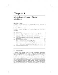
propensity of the membranes in order to mimic extracellular polymeric substances commonly present in wastewater effluents. Representative fouling curves for the NMP-TFC and DMF-TFC membranes are presented in Figure 1A, and the summarized flux decline data with duplicate experiments can be found in the Supporting Information (Figure S1 and Table S1). Generally, the loss of water flux due to fouling was relatively small for both membranes (Figure 1A), considering the extremely high foulant concentrations (250 mg/L) used. This observation is consistent with previous FO fouling studies, which demonstrated the low fouling propensity of FO membranes.30,31 The NMP-TFC membranes exhibited significantly smaller water flux decline (7.47 ± 0.15%) than the DMF-TFC membranes (12.7 ± 2.62%). Physical cleaning also led to greater recovery of water flux for the NMP-TFC membrane (Figure S1 and Table S1). Both of these results indicate a lower fouling propensity for the NMP-TFC membrane than for the DMF-TFC membrane. Foulant−Membrane Interaction Forces. The observed fouling propensities of the membranes were in agreement with the corresponding foulant−membrane interaction forces.15,32 The distribution of probe−membrane adhesion forces for the NMP-TFC membrane (Figure 2A) was shifted toward the right (i.e., lower adhesion forces) relative to that of the DMF-TFC membrane (Figure 2B). This resulted in a relatively lower mean adhesion force of −0.38 ± 0.31 mN m−1 for the NMP-TFC membrane compared to that of −0.60 ± 0.34 mN m−1 for the DMF-TFC membrane. In addition, a significantly higher fraction of the measurements performed on the NMP-TFC membrane (22.6% vs 3.3% for the DMF-TFC membrane) exhibited no detectable adhesion force (counted in the “NO” column), implying the absence of adhesion probe−membrane interactions. As shown in Figure 2C,D, the DMF-TFC membrane had more “sticky” sites, indicated by more frequent measurement (50%) of rupture distances larger than 100 nm 1439
DOI: 10.1021/es5044062 Environ. Sci. Technol. 2015, 49, 1436−1444
Article
Environmental Science & Technology
3.47 ± 0.43 bar−1 for the NMP-TFC and 6.16 ± 2.68 bar−1 for the DMF-TFC membrane. Given the same initial water flux (∼21 L m−2 h−1) for both types of membranes in the fouling experiments, a lower A/B value implies greater reverse solute diffusion, Js, for the NMP-TFC membrane, which would cause greater water flux decline. However, the decline in water flux was less severe for the NMP-TFC membrane in our fouling experiments, which rules out this mechanism as the cause for the different fouling propensities. (b). Is It Disruption of Calcium−Alginate Complexes by Sodium? The calcium ions in our simulated wastewater feed solution facilitate bridging and complexation between carboxyl groups on the polyamide surface and alginate molecules.34−36 The gel network that consequently forms on the active layer could impede water flux. At the same time, sodium ions could disrupt calcium bridges between foulant molecules through cation exchange.37−39 Given the higher reverse solute diffusion for the NMP-TFC membrane, and our use of NaCl as the draw solute, the lower fouling propensity of this membrane could be attributed to greater disruption of calcium bridging and complexation by the sodium ions. To further evaluate this possibility, we repeated our fouling experiments with MgCl2 as the draw solute, which does not have the cation exchange capability of NaCl. The fouling behaviors of the TFC membranes evaluated with MgCl2 draw solution are presented in Figure 1B. Even without the influx of sodium ions from the draw solution to the foulant layer, the NMP-TFC membrane still exhibited a lower flux decline (78.8 ± 5.7%) than the DMFTFC membrane (66.5 ± 4.5%). Therefore, the lower fouling propensity of the NMP-TFC membrane cannot be attributed to differences in the degree of cation exchange occurring between sodium and calcium ions. (c). Is It Membrane Surface Hydrophilicity or Chemistry? Surface energy and surface chemistry strongly influence the interaction of organic foulants with the membrane surface. The layer of strongly bound water molecules that forms on a hydrophilic surface through hydrogen bonding provides an enthalpic penalty for foulant adhesion that lowers fouling propensity.40,41 The density of carboxyl groups on a surface also affects fouling propensity through the availability of sites for calcium−alginate complexation with the surface.42,43 To determine whether differences in surface hydrophilicity or chemistry might explain the observed difference in fouling propensity, we measured water contact angle and the density of native carboxyl groups on the polyamide surfaces (Table 1). Although identical interfacial polymerization procedures were performed on both membrane types, the DMF-TFC membrane had lower value (P-value < 0.001) in water contact angle (55.7 ± 6.6° vs 66.4 ± 2.3°, respectively) and comparable carboxyl group density (18.96 ± 3.66 nm−2 vs 20.24 ± 6.17 nm−2) compared to the NMP-TFC membrane. This would suggest less propensity for fouling due to greater hydrophilicity and fewer sites for carboxyl-group-facilitated foulant attachment. However, the observed overall fouling propensity is higher for the DMF-TFC membrane, thereby ruling out both surface hydrophilicity and surface chemistry explanations for the observed fouling behavior. (d). Is It Membrane Surface Structure? During interfacial polymerization, MPD diffuses into the organic phase, where it reacts with TMC to form the polyamide layer with its characteristic ridge-and-valley structure.4,44 The inherent roughness of this polyamide structure can enhance membrane fouling through (i) greater surface area for foulant attachment and (ii)
Figure 1. FO alginate fouling results with (A) NaCl and (B) MgCl2 draw solutions. Fouling conditions were as follows: feed solution chemistry simulating domestic wastewater (pH 7.4) as described in the Materials and Methods, supplemented with 250 mg/L alginate as model organic foulant; draw solutions of (A) 2−4 M NaCl and (B) 2− 3.5 M MgCl2, resulting in an initial permeate water flux of ∼21 L m−2 h−1. The system temperature was maintained at 25 °C, and the crossflow velocity of the feed and draw streams was set to 8.5 cm/s. To reduce experimental noise, data were smoothed using a 5-point window moving average. Note that y-axis scales differ.
membrane, this could explain why its decline in water flux was less than that of the DMF-TFC membrane. Because the two TFC membranes have different transport properties, different initial draw solution concentrations were required to reach the same initial water flux (∼21 L m−2 h−1). To analyze the effect of reverse solute diffusion on fouling, we determined the reverse solute flux selectivity:33 Jw A = nR gT Js B (1) where Jw is water flux, Js is the reverse solute flux, A and B are water and salt permeability coefficients, respectively, n is the number of dissolved species created by the draw solute (2 for NaCl), Rg is the ideal gas constant, and T is the absolute temperature. The reverse solute flux selectivity is independent of draw solution concentration, and can be obtained simply from the ratio A/B. The calculated A/B values (Table 1) are 1440
DOI: 10.1021/es5044062 Environ. Sci. Technol. 2015, 49, 1436−1444
Article
Environmental Science & Technology
Figure 2. Distribution of foulant−membrane adhesion forces and rupture distance for active layers formed on polysulfone support using different solvents: NMP (upper row) and DMF (lower row). Measurements were performed by contact mode AFM at room temperature in a liquid cell filled with synthetic wastewater (pH 7.4). At least 125 retraction force measurements distributed over five randomly chosen locations were performed for each sample. The columns labeled “NO” indicate the fraction of the population of force measurements for which no adhesion was observed.
Figure 3. Roughness parameters measured by AFM tapping mode analysis. (A) Polyamide surface and (B) polysulfone surface. Rrms is the rootmean-square of roughness, Ra is the average roughness, and Rmax/10 is the maximum roughness divided by a factor of 10. Roughness values shown averaged together from a total of 6 random spots on three separately cast membrane samples. Error bars indicate one standard deviation. Note that yaxis scales differ.
membranes fabricated under similar conditions.31,45 The surface roughness of the DMF-TFC membrane was higher (P-value < 0.001) than that of the NMP-TFC membrane (Figure 3A), with Rrms, of 124.39 ± 5.68 nm, Ra of 98.19 ± 3.79 nm, and Rmax of 969.64 ± 144.53 nm. This is the first comparison between the membranes for which the observed fouling trend agrees with what we would predict from a specific surface characteristic.
accumulation of foulants in valley features that can hinder their removal during physical cleaning.18 We used AFM to quantify membrane surface roughness (Figure 3) and SEM to inspect surface morphology (Figure 4). The NMP-TFC membrane had a root-mean-square roughness (Rrms) of 94.41 ± 3.59 nm, an average roughness (Ra) of 74.64 ± 3.22 nm, and a maximum roughness (Rmax) of 696.42 ± 34.84 nm. These values are comparable to those of 1441
DOI: 10.1021/es5044062 Environ. Sci. Technol. 2015, 49, 1436−1444
Article
Environmental Science & Technology
Figure 4. SEM micrographs displaying the structure of the TFC FO membranes at the (top row) surface of the polyamide layer imaged at 45° angle of incidence and at lower magnification, with yellow arrows indicating the nodular (NMP-TFC) and leaf-like (DMF-TFC) structures of the polyamide surfaces; (middle row) surface of the polyamide layers at equal magnification with (bottom row) the top surface of the bare polysulfone support layers (yellow arrows indicate pores). Membranes formed using NMP are shown on the left and those formed using DMF are shown on the right.
the support layer itself. Below, we employ further characterization of the support layers to examine the current understanding of the role of support layer characteristics on polyamide formation and foulant accumulation on the membrane surface. (a). Origin of Polyamide Layer Structure. Figure 3B depicts surface roughness of the polysulfone supports, which is much lower than the roughness of the polyamide surfaces (Figure 3A). Slightly lower values in Rrms, Ra, and Rmax of the DMFpolysulfone indicate that this support is smoother than the NMP-polysulfone support. We note that the converse is observed for polyamide roughness, i.e., the DMF-TFC polyamide surface is rougher than the NMP-TFC polyamide surface. These results indicate that the high roughness features of the polyamide active layers are neither a translation nor simple amplification of the support layer roughness. High magnification SEM micrographs of the polyamide and polysulfone surfaces were also compared (Figure 4C−F). Previous studies23,46 speculated that each individual ridge (or nodule) in the polyamide layer arises from one underlying pore in the support layer; we refer to this herein as the “one pore− one ridge” model. This proposed mechanism for polyamide roughness formation was based on an observed trend between pore size and polyamide feature size. Although we note the same trend, that the NMP-TFC membrane has both smaller polysulfone surface pores and smaller polyamide features, when micrographs of the polyamide and polysulfone surfaces are
SEM micrographs of the NMP-TFC and DMF-TFC membrane polyamide surfaces show the expected ridge-andvalley structure (Figure 4A,B, additional replicate in the Supporting Information, Figure S3). These micrographs were obtained with a 45° stage tilt in order to supplement the topdown perspective provided by SEM. The surface of the NMPTFC membrane contained many small, nodular features, while the DMF-TFC membrane surface included some larger leaf-like structures (these unique features are indicated by yellow arrows in Figure 4A,B). These leaf-like structures overhang the membrane surface, potentially providing regions where foulants can accumulate and be sheltered from the shear forces produced during physical cleaning.18 The difficulty of quantifying the morphology of the polyamide layer prevents us from conclusively tying this factor to our observed fouling propensity, as we did for roughness. However, we can recognize the possibility that the larger overhanging features of the DMFTFC polyamide layer might make the buildup of foulants on the DMF-TFC membranes more rapid and less reversible, as observed in our fouling experiments. If this mechanism is at work as we propose, its effects on fouling are combined with those associated with roughness differences to determine the overall fouling propensity. Relating Polyamide Surface Properties to Support Layer Structure. Our finding that subtle changes to the support layer affect polyamide structure in a way that significantly alters fouling propensity warrants a closer look at 1442
DOI: 10.1021/es5044062 Environ. Sci. Technol. 2015, 49, 1436−1444
Environmental Science & Technology
■
compared side-by-side at equal magnification, it becomes very clear that the one pore−one ridge proposed model is not consistent with our SEM micrographs. The polyamide features (Figure 4C,D) are at least 1 order of magnitude larger than the pores on the polysulfone support (Figure 4E,F), and the base of each polyamide ridge covers an area occupied by many polysulfone pores (>10). (b). Importance for Active Layer Fouling Behavior. A recent modeling effort26 proposed that a more permeable support might contribute to a more uniform spatial distribution of water permeation across the TFC membrane surface, resulting in a surface with lower fouling propensity. Conversely, a less permeable support would constrain water transport to occur over a reduced effective area, through scattered points with relatively high local water fluxes, referred to as hot spots. Such a membrane would have a higher fouling propensity. In our experiments, we found that the support layer of the lower fouling propensity membrane (NMP-TFC) did have a higher water permeability (Table 1, 1107 ± 193 vs 290 ± 40 L m−2 h−1 bar−1 for the DMF-TFC support), in basic agreement with the hot-spots theory. However, further analysis (see the Supporting Information, section S4) showed that overall water permeability of the support layers was primarily determined by the bulk structure rather than by the dense skin layer. This indicated that the overall support permeability might not accurately reflect water transport through the dense skin layer and adjacent polyamide layer. We therefore turned to more direct characterizations of the support layer surface to inform the comparison of our fouling observations with the proposed hot-spots mechanism. The surfaces of the support layers had comparable pore density (Table 1), but the DMF-TFC membrane support surface had a larger pore size (as shown in Figures 4E,F and S2, Supporting Information) and higher surface porosity (1.99 ± 0.60% vs 1.01 ± 0.40%, Table 1). Therefore, the DMF-TFC membrane would have a greater amount of area available for water permeation at the polysulfone−polyamide interface. Fouling propensity would consequently be expected to be lower for the DMF-TFC membrane; however, we observed the opposite. This finding does not negate the plausibility of the hot-spots theory. Rather, it shows that, if the theory is correct, the effect of polysulfone surface pore size and porosity on polyamide layer fouling in our membranes was overcome by more influential differences in the structure of the polyamide layers. Implications for TFC Membrane Fabrication. Much research effort over the past few years has focused on obtaining a support layer with a structure that minimizes internal concentration polarization in forward osmosis. Our work demonstrates that changes made to the support layer may have unintended and unexamined effects on fouling propensity for TFC membranes. Our comparison of just two slightly different membranes does not support development of a comprehensive model to quantitatively relate support layer structure or fabrication choices to the fouling propensity ultimately observed on an overlying active layer. However, it does highlight the importance of evaluating supposed improvements to support layers for their impact on fouling propensity or on factors known to influence fouling propensity, like those we have presented here.
Article
ASSOCIATED CONTENT
S Supporting Information *
Details on the evaluation of TFC membrane intrinsic properties (S1); evaluation of polysulfone support properties (S2); physical cleaning methodology (S3); polysulfone support thickness measurements (S4); analysis on support layer structure and resistance to water transport (S5); selection or exclusion of potential techniques for evaluating fouling propensity (S6); FO fouling and cleaning experiment results (Figure S1 and Table S1); pore diameter distribution of support surfaces (Figure S2); replicate SEM micrographs of polyamide layers (Figure S3). This material is available free of charge via the Internet at http://pubs.acs.org.
■
AUTHOR INFORMATION
Corresponding Authors
*J.M. E-mail:
[email protected]. Tel: +86 451 86283010. Fax: +86 451 86283010. *M.E. E-mail:
[email protected]. Tel: +1 203 432 2789. Fax: +1 203 432 4387. Notes
The authors declare no competing financial interest.
■
ACKNOWLEDGMENTS Financial support from the Department of Defense through the Strategic Environmental Research and Development Program (SERDP, Project No. 12 ER01-054/ER-2217) and the National Science and Technology Pillar Program of China (Project No. 2012BAC05B02) is gratefully acknowledged. We also acknowledge the use of SEM and AFM facilities supported by the Yale Institute for Nanoscience and Quantum Engineering (YINQE) under NSF MRSEC DMR 1119826. This publication was developed under a graduate fellowship awarded by the China Scholarship Council (CSC) to Xinglin Lu and STAR Fellowship (Agreement No. FP-91733801-0) awarded by the U.S. Environmental Protection Agency (EPA) to L.H. Arias Chavez. It has not been reviewed or endorsed by the U.S. EPA.
■
REFERENCES
(1) Shannon, M. A.; Bohn, P. W.; Elimelech, M.; Georgiadis, J. G.; Marinas, B. J.; Mayes, A. M. Science and technology for water purification in the coming decades. Nature 2008, 452 (7185), 301− 310. (2) Elimelech, M.; Phillip, W. A. The future of seawater desalination: Energy, technology, and the environment. Science 2011, 333 (6043), 712−717. (3) Hoover, L. A.; Phillip, W. A.; Tiraferri, A.; Yip, N. Y.; Elimelech, M. Forward with osmosis: Emerging applications for greater sustainability. Environ. Sci. Technol. 2011, 45 (23), 9824−30. (4) Petersen, R. J. Composite reverse-osmosis and nanofiltration membranes. J. Membr. Sci. 1993, 83 (1), 81−150. (5) Yip, N. Y.; Tiraferri, A.; Phillip, W. A.; Schiffman, J. D.; Elimelech, M. High performance thin-film composite forward osmosis membrane. Environ. Sci. Technol. 2010, 44 (10), 3812−3818. (6) Wei, J.; Qiu, C.; Tang, C. Y.; Wang, R.; Fane, A. G. Synthesis and characterization of flat-sheet thin film composite forward osmosis membranes. J. Membr. Sci. 2011, 372 (1−2), 292−302. (7) Wang, R.; Shi, L.; Tang, C. Y.; Chou, S.; Qiu, C.; Fane, A. G. Characterization of novel forward osmosis hollow fiber membranes. J. Membr. Sci. 2010, 355 (1−2), 158−167. (8) Cath, T. Y.; Childress, A. E.; Elimelech, M. Forward osmosis: Principles, applications, and recent developments. J. Membr. Sci. 2006, 281 (1−2), 70−87. 1443
DOI: 10.1021/es5044062 Environ. Sci. Technol. 2015, 49, 1436−1444
Article
Environmental Science & Technology (9) Kumar, M.; Adham, S. S.; Pearce, W. R. Investigation of seawater reverse osmosis fouling and its relationship to pretreatment type. Environ. Sci. Technol. 2006, 40 (6), 2037−2044. (10) Tang, C. Y.; Kwon, Y.-N.; Leckie, J. O. Fouling of reverse osmosis and nanofiltration membranes by humic acidEffects of solution composition and hydrodynamic conditions. J. Membr. Sci. 2007, 290 (1−2), 86−94. (11) Xu, P.; Bellona, C.; Drewes, J. E. Fouling of nanofiltration and reverse osmosis membranes during municipal wastewater reclamation: Membrane autopsy results from pilot-scale investigations. J. Membr. Sci. 2010, 353 (1−2), 111−121. (12) Ang, W. S.; Elimelech, M. Protein (BSA) fouling of reverse osmosis membranes: Implications for wastewater reclamation. J. Membr. Sci. 2007, 296 (1−2), 83−92. (13) Li, Q.; Xu, Z.; Pinnau, I. Fouling of reverse osmosis membranes by biopolymers in wastewater secondary effluent: Role of membrane surface properties and initial permeate flux. J. Membr. Sci. 2007, 290 (1−2), 173−181. (14) Rana, D.; Matsuura, T. Surface modifications for antifouling membranes. Chem. Rev. 2010, 110 (4), 2448−2471. (15) Lu, X.; Romero-Vargas Castrillón, S.; Shaffer, D. L.; Ma, J.; Elimelech, M. In situ surface chemical modification of thin-film composite forward osmosis membranes for enhanced organic fouling resistance. Environ. Sci. Technol. 2013, 47 (21), 12219−12228. (16) Yu, H.-Y.; Kang, Y.; Liu, Y.; Mi, B. Grafting polyzwitterions onto polyamide by click chemistry and nucleophilic substitution on nitrogen: A novel approach to enhance membrane fouling resistance. J. Membr. Sci. 2014, 449, 50−57. (17) Romero-Vargas Castrillón, S.; Lu, X.; Shaffer, D. L.; Elimelech, M. Amine enrichment and poly(ethylene glycol) (PEG) surface modification of thin-film composite forward osmosis membranes for organic fouling control. J. Membr. Sci. 2014, 450, 331−339. (18) Vrijenhoek, E. M.; Hong, S.; Elimelech, M. Influence of membrane surface properties on initial rate of colloidal fouling of reverse osmosis and nanofiltration membranes. J. Membr. Sci. 2001, 188 (1), 115−128. (19) Hobbs, C.; Hong, S. K.; Taylor, J. Effect of surface roughness on fouling of RO and NF membranes during filtration of a high organic surficial groundwater. J. Water Supply Res. Technol.AQUA 2006, 55 (7−8), 559−570. (20) Gu, Y.; Wang, Y.-N.; Wei, J.; Tang, C. Y. Organic fouling of thin-film composite polyamide and cellulose triacetate forward osmosis membranes by oppositely charged macromolecules. Water Res. 2013, 47 (5), 1867−1874. (21) Singh, P. S.; Joshi, S. V.; Trivedi, J. J.; Devmurari, C. V.; Rao, A. P.; Ghosh, P. K. Probing the structural variations of thin film composite RO membranes obtained by coating polyamide over polysulfone membranes of different pore dimensions. J. Membr. Sci. 2006, 278 (1−2), 19−25. (22) Kim, H. I.; Kim, S. S. Plasma treatment of polypropylene and polysulfone supports for thin film composite reverse osmosis membrane. J. Membr. Sci. 2006, 286 (1−2), 193−201. (23) Ghosh, A. K.; Hoek, E. M. V. Impacts of support membrane structure and chemistry on polyamide-polysulfone interfacial composite membranes. J. Membr. Sci. 2009, 336 (1−2), 140−148. (24) Tiraferri, A.; Yip, N. Y.; Phillip, W. A.; Schiffman, J. D.; Elimelech, M. Relating performance of thin-film composite forward osmosis membranes to support layer formation and structure. J. Membr. Sci. 2011, 367 (1−2), 340−352. (25) Hoek, E. M. V.; Bhattacharjee, S.; Elimelech, M. Effect of membrane surface roughness on colloid-membrane DLVO interactions. Langmuir 2003, 19 (11), 4836−4847. (26) Ramon, G. Z.; Hoek, E. M. V. Transport through composite membranes, part 2: Impacts of roughness on permeability and fouling. J. Membr. Sci. 2013, 425−426, 141−148. (27) Ben-Asher, J. Irrigation with saline water. GeoJournal 1987, 15 (3), 267−272. (28) Senden, T. J. Force microscopy and surface interactions. Curr. Opin. Colloid Interface Sci. 2001, 6 (2), 95−101.
(29) Tiraferri, A.; Elimelech, M. Direct quantification of negatively charged functional groups on membrane surfaces. J. Membr. Sci. 2012, 389, 499−508. (30) Lee, S.; Boo, C.; Elimelech, M.; Hong, S. Comparison of fouling behavior in forward osmosis (FO) and reverse osmosis (RO). J. Membr. Sci. 2010, 365 (1−2), 34−39. (31) Tiraferri, A.; Kang, Y.; Giannelis, E. P.; Elimelech, M. Highly hydrophilic thin-film composite forward osmosis membranes functionalized with surface-tailored nanoparticles. ACS Appl. Mater. Interfaces 2012, 4 (9), 5044−5053. (32) Li, Q.; Elimelech, M. Organic fouling and chemical cleaning of nanofiltration membranes: measurements and mechanisms. Environ. Sci. Technol. 2004, 38 (17), 4683−4693. (33) Phillip, W. A.; Yong, J. S.; Elimelech, M. Reverse draw solute permeation in forward osmosis: modeling and experiments. Environ. Sci. Technol. 2010, 44 (13), 5170−5176. (34) Lee, S.; Elimelech, M. Relating organic fouling of reverse osmosis membranes to intermolecular adhesion forces. Environ. Sci. Technol. 2006, 40 (3), 980−987. (35) Liu, Y.; Mi, B. Combined fouling of forward osmosis membranes: Synergistic foulant interaction and direct observation of fouling layer formation. J. Membr. Sci. 2012, 407−408, 136−144. (36) Xiang, Y.; Liu, Y.; Mi, B.; Leng, Y. Molecular dynamics simulations of polyamide membrane, calcium alginate gel, and their interactions in aqueous solution. Langmuir 2014, 30 (30), 9098−9106. (37) Lee, S.; Elimelech, M. Salt cleaning of organic-fouled reverse osmosis membranes. Water Res. 2007, 41 (5), 1134−1142. (38) Skjåk-Bræk, G.; Grasdalen, H.; Smidsrød, O. Inhomogeneous polysaccharide ionic gels. Carbohydr. Polym. 1989, 10 (1), 31−54. (39) Matsumoto, T.; Mashiko, K. Viscoelastic properties of alginate aqueous solutions in the presence of salts. Biopolymers 1990, 29 (14), 1707−1713. (40) van Oss, C. J.; Chaudhury, M. K.; Good, R. J. Monopolar surfaces. Adv. Colloid Interface Sci. 1987, 28 (1), 35−64. (41) van Oss, C. J.; Wu, W.; Docoslis, A.; Giese, R. F. The interfacial tensions with water and the Lewis acid-base surface tension parameters of polar organic liquids derived from their aqueous solubilities. Colloids Surf., B 2001, 20 (1), 87−91. (42) Jin, X.; Huang, X. F.; Hoek, E. M. V. Role of specific ion interactions in seawater RO membrane fouling by alginic acid. Environ. Sci. Technol. 2009, 43 (10), 3580−3587. (43) Wu, J.; Contreras, A. E.; Li, Q. Studying the impact of RO membrane surface functional groups on alginate fouling in seawater desalination. J. Membr. Sci. 2014, 458, 120−127. (44) Freger, V. Kinetics of film formation by interfacial polycondensation. Langmuir 2005, 21 (5), 1884−1894. (45) Tang, C. Y. Y.; Kwon, Y. N.; Leckie, J. O. Effect of membrane chemistry and coating layer on physiochemical properties of thin film composite polyamide RO and NF membranes II. Membrane physiochemical properties and their dependence on polyamide and coating layers. Desalination 2009, 242 (1−3), 168−182. (46) Klaysom, C.; Hermans, S.; Gahlaut, A.; Van Craenenbroeck, S.; Vankelecom, I. F. J. Polyamide/polyacrylonitrile (PA/PAN) thin film composite osmosis membranes: Film optimization, characterization and performance evaluation. J. Membr. Sci. 2013, 445, 25−33.
1444
DOI: 10.1021/es5044062 Environ. Sci. Technol. 2015, 49, 1436−1444