International Congress Motor Vehicles & Motors 2018 Kragujevac, Serbia October 4th - 5th, 2018
Motor Vehicles & Motors
MVM2018-064 Saša Milojević Radivoje Pešić2 Aleksandar Davinić3 Dragan Taranović4 Snežana Petković5 Emil Hnatko6 Radmilo Stefanović7 Stevan Veinović8 1
INFLUENCE OF VARIABLE COMPRESSION RATIO ON EMISSION AND VIBE FUNCTION PARAMETERS OF EXPERIMENTAL ENGINE ABSTRACT: Compression ratio as a constructive parameter has a very important influence on fuel economy, emission and other performances of internal combustion engines. Introduction of variable compression ratio has the number of benefits: limiting maximal in-cylinder pressure, extended field of the optimal operating regime with minimal fuel consumption, more power, reduced exhaust emission and controlled noise emission. It is particularly characteristic for multifuel capability of engines with variable compression ratio (VCR), along the control of maximum temperature and pressure in the cylinders. The paper presents engines and mechanisms for automatic change of compression ratio value. Modelling of operation process of internal combustion (Otto and Diesel) engines with direct injection has been performed in parallel with experimental research. The basic problem is the selection of the parameters in double Vibe function used for modelling of the diesel engine operation process, also performed for different compression ratio. The optimal compression ratio value was defined regarding the minimal fuel consumption and exhaust emission. For this purpose, the test bench is brought into operation in the Laboratory for Engines of the Faculty of Engineering, University of Kragujevac.
KEYWORDS: IC engine, emission, variable compression ratio, Vibe function
Dipl.Ing. Saša Milojević, assistant R&D. University of Kragujevac, Faculty of Engineering, Serbia, Kragujevac, Sestre Janjić 6,
[email protected] 2 Dr.Ing. Radivoje Pešić, prof. University of Kragujevac, Faculty of Engineering, Serbia, Kragujevac, Sestre Janjić 6,
[email protected] 3 Dr.Ing. Aleksandar Davinić,assist. prof. University of Kragujevac, Faculty of Engineering, Serbia, Kragujevac, Sestre Janjić 6,
[email protected] 4 Dr.Ing. Dragan Taranović, assoc. prof. University of Kragujevac, Faculty of Engineering, Serbia, Kragujevac, Sestre Janjić 6,
[email protected] 5 Dr.Ing. Snežana Petković, prof. University of Banja Luka, Faculty of Mechanical Engineering, Republic of Srpska, Banja Luka, Bulevar vojvode Petra Bojovića 1A,
[email protected] 6 Dr.Ing, Emil Hnatko, University of Osijek, Mechanical Engineering Faculty in Slavonski Brod, Croatia,
[email protected] 7 Dipl.Ing. Radmilo Stefanović, Consultant. Serbia, Belgrade,
[email protected] 8 Dr.Ing. Stevan Veinović, retired prof. University of Kragujevac, Faculty of Engineering, Serbia, Kragujevac, Sestre Janjić 6,
[email protected] 1
227
INTRODUCTION City traffic and traffic flow have the greatest impact on the exhaust emission and air pollution, specifically in the street canyons, zones of city centres, etc. Moreover, in city area, the traffic can contribute substantially in declining of exhaust emission, by application of various methods. According to our practical experience, there are currently two real directions: 1. to switch on alternative fuels, natural gas and hydrogen as driving energy, with parallel introduction of flexible transport, which enables the decrease in the number of vehicles in urban centres to avoid congestion [18] and 2. further tribological optimization of conventional internal combustion (IC) engines by lowering internal friction and mechanical losses, in order to reduce fuel consumption and exhaust emission [911]. Regarding the first proposed direction, nowadays, application of gaseous fuels such as hydrogen and natural gas as well as their mixtures is more and more interesting in optimized IC engines [1219]. Natural gas is a highquality fuel for motor vehicles. Above all, available reserves equal the known oil reserves; negative influence upon environment is less than with fuels derived from oil, as well as is the price. Thus, natural gas as engine fuel has been having a growing application in motor vehicles, which is further proved by the fact that there are over 26 million vehicles in the world powered by natural gas (1.86 million in Europe). Currently, there are 878 natural gas vehicles (792 passenger and light duty vehicles, 58 buses and 28 medium and heavy duty trucks) in traffic on the roads in the Republic of Serbia [20]. In terms of engine related criteria, natural gas may be used as the sole fuel for Otto or diesel engines (with certain engine reconstruction), firstly in engines with automatic variable compression ratio (VCR). In addition, it may be used in mixture with every kind of oil or proved alternative fuel (lower or higher alcohols, biogas and other) [2124]. In normal ambient conditions, natural gas has a low density of energy per unit volume. Thus, in case of application of natural gas as a motor fuel, it is necessary to have a certain treatment of natural gas in order to have a higher concentration of energy by unit volume. Given that it is expected to provide a wider radius of vehicle movement with one fuel tank supply, it is necessary to have operating pressures of around 200 bar. The simplest way is to compress natural gas in high-pressure tanks (CNG compressed natural gas). The second alternative for increasing the density of energy of natural gas inside tanks on vehicles is its extreme cooling down to 162C, i.e. conversion to liquefied state (LNG liquefied natural gas) and storing in cryogenic tanks [25]. In California (California Environment Protection Agency EPA) and Japan, there are standards for natural gas as the engine fuel. In the United States federal regulations, the natural gas composition is defined as a reference fuel for testing exhaust emissions, Table 1 [2527]. Table 1 Specification of the natural gas according to the California EPA standard (01.05.1999.) and the reference fuel to the Federal EPA characteristics California EPA Federal EPA Test method Specification Value Methane 88 mol.% (min.) 89 mol.% (min.) Ethane 6.0 mol. % (max.) 4.5 mol. % (max.) C3 higher HC 3.0 mol. % (max.) 2.3 mol. % (max.) ASTM D 1945-81 C6 higher HC 0.2 mol. % (max.) 0.2 mol. % (max.) Oxygen 1.0 mol. % (max.) 0.6 mol. % (max.) CO2 and N2 1.5-4.5 mol.% 4.0 mol. % (max.) Hydrogen 0.1 mol. % (max.) ASTM 2650-88 CO 0.1 mol. % (max.) It should not contain dust, sand, mud, rubber, oil and other substances that could damage Particulate matter the equipment or the charging station equipment of the vehicle Sulphur 16 ppm vol. (max.) Title 17 CCR Section 94112 Odor Unpleasant and specific in 1/5 lower limit of inflammation Optimistic studies about natural gas are based on pure methane. Unfortunately, pure methane is nowhere to be found in nature. It is always in mixture with other impurities in concentration of various percentages. In order to use natural gas as a fuel, it is necessary to filter it until it reaches more or less the established composition and quality. There are some national standards that regulate quality of natural gas as engine fuel: SAE J1616, DIN 51624 and 13 CCR § 2292.5 (California regulations). In parallel, there is an international standard ISO 15403, accepted also by the Republic Serbia. The purpose of this standard is for producers, vehicle users, filling station operators and other logistics participants in the industry to get informed about quality of fuel for natural gas vehicles. 228
In the second case, the development of vehicle powertrains is increasingly challenged by emission legislation and by the “end-users” fuel economy demands. In order to meet these requirements it is necessary to continuously improve existing powertrains and to develop totally new generations of engines, while still giving space for individual brandspecific features. According to theoretical studies, the overall effect of IC engines (either Otto or diesel) can be improved, since Otto engines can be improved up to 40% and the best diesel engines up to 50%. Efficiency of over 50% is achieved only by two-stroke marine diesel engines (55%) [11, 28]. The current IC engines have serious reservations to improve fuel economy, Figure 1. Average efficiency at the optimum point is about 30% in automotive engines and about 45% in marine engines [11].
Figure 1 Mercedes-Benz completes vehicle ML 300 CDI and engine rebuild 2.4 l per 100 km. Percent reduction in fuel consumption at 2.4 l per 100 km compared to the previous model ML 300 CDI: 36% f ourcylinder diesel engine; 16% eco startstop system; 14% 7GTRONIC PLUS automatic transmission with fuel economy converter; 12% reduction of the driving resistance; 7% electromechanical steering system; 5% consumptionoptimized axle drive; 3% generator management; 3% regulated fuel pump; 2% optimized belt drive with decouple; and 2% clutch and air conditioning compressor For vehicles, working range loadengine speed at minimum fuel consumption is very close. Its expansion is a chance for engines with variable systems. A further advantage of such engines is the ability to work with all types of available liquid and gaseous fuels with the fulfilment of environmental regulations. Energy efficiency propulsion system will be the number one priority for the future, a model for the comparison of the Airbus A380, whose engine consumes less then 3 l per 100 km of fuel per passenger (78 passengermiles per US gallon). Criteria for environmentally friendly drives must be defined in accordance with scientifically based facts [11]. The fourstroke engine known to date, have come from Nikolaus August Otto more than 150 years ago. The magical limit of about 12.5:1, as the optimum combustion chamber defined by a fuel quality, is above the range reserved for diesel engines [11]. The starting point is the fact that the mechanical efficiency of the IC engines is dependent on energy losses associated with friction i.e. the conditions inside tribological system which consists of: piston, piston rings and cylinder liner. Generally, mechanical efficiency lowers in case of raising the compression ratio (CR) and vice versa. This leads to a minor mechanical problems, but achieves lower fuel consumption. This is the future of the gasoline engine - to finally equalize the consumption of diesel engines [2935]. The problem is in the fact that the geometric CR of IC engines is set as a compromise between partial and full-load requirements. The demand for the highest geometric CR to improve high partload efficiency is opposed by a knock (gasoline engines) or peak pressure limitations with the Diesel engines. When CR is raised from 10 to 15:1, efficiency increases by more than 20%! The boundaries of efficiency of heat engine are about 55%, which results in the consumption of about 160 gkWh1. Currently, most car engines have the CR around 11:1, efficiency of about 35% and consumption of approximately 250 gkWh1, but in a very narrow field [36].
229
The increasing load (BMEP brake mean effective pressure) and power ranges enhanced the compromises to be taken with deciding on a fixed CR. With gasoline engines, a quite clear correlation between the maximum load and geometric CR ratio is evident even with a simple statistical observation of actual production engines [37]. The downsizing technology in the recent years has even enhanced this tradeoff. Compared to naturally aspirated (NA) engines with direct injection (DI) or multi point injection (MPI), the higher specific power and BMEP levels of turbocharged engines require a lowered CR at full load, while the demand for high CR at partial loads is highly exacerbated by the fuel consumption requirements. Looking at the distribution of the specific power versus engine displacement, high performance is no longer restricted to multi cylinder sport cars, Figure 2 [37].
Figure 2 Specific powers of gasoline engines and development trends According to previous, VCR method is used to determine optimal CR for gasoline and diesel engines under different loads [38, 39] in combination with other variable systems on engine, such as: flexible intake valve actuation [40], exhaust gas recirculation (EGR) [41], variable fuel injection time [42, 43], etc. Generally, with integrated system for VCR, it is possible to increase engine efficiency, power and torque. The engine can operate under multiple cycles with multifuel capability i.e. well adjust to knock limitations when using various fuels. Optimization of IC engines is related to equipment through which natural gas (or any other alternative fuel) is directly injected into the combustion chambers. Compression ratio is self-regulated and it adapts to engine fuel quality and manages workflows according to the basic requirements: economy, power, torque, ecology, noise and so on. Today's technical development allows simultaneous management of combustion processes by Otto and/or Diesel cycle, according to the driving conditions. Such engine freedom offered technological relief for oil industry in the formulation of a new (and the same for Otto and diesel engines) energy efficient and environmentally friendly fuel, Figure 3.
Figure 3 New concept of multi-process IC engine
230
The main reason for the growth in engine modelling activities arises from the economic benefits. By using computer models, large savings are possible in expensive experimental work, when engine modifications are being considered. Models cannot replace real engine testing but they are able to provide good estimates of performance changes resulting from possible engine modifications and, thus, can help in selecting the best options for further development, reducing the amount of hardware development required. While the more advanced models are extremely large and complex, the basics of an engine thermodynamic model are quite straightforward and easily understood. The complexity arises later in the refinement of the calculation methods, the level of detail of sub-system representation and the accommodation of a wide variety of alternative engine configurations and control systems. The authors have also successfully studied the influence of CR on combustion process in experimental engine. Validation of the results received by using the model of the diesel process with double Vibe function was carried out in parallel by their comparison with relevant results obtained during experimental measurements [1]. The main goal of the paper is to determine the influence of CR and engine working regimes on the combustion characteristics and shape parameters of double Vibe function, as well as, on the fuel consumption and exhaust emission. Detailed results of experimental measurements are presented in [1].
OVERVIEW OF VCR MECHANISMS All companies working on development projects of VCR engine state that applying VCR engines can solve the problems of economy and ecology. The operating versions are usually systematized according to the similarities. Numerous construction solutions of VCR engines and systems can be found in the literature. Certain constructions have been practically realized. All kinematic solutions can be used as combined patent rights, and sometimes as a serious contribution to constructive thinking. VCR mechanisms can be realized with variable cylinder head volume or with variable position of piston top dead centre (TDC), Figure 4 [37].
Figure 4 Variants of variable compression ratio: 1) Variable volume in combustion chamber: (a; b) secondary piston for adjust the clearance volume; 2) Variable cylinder height: (a) cylinder moves up by translation; (b) cylinder moves up by rotation; (c) eccentric crankshaft, effectively adjusts link lengths; 3) Variable compression height: (a) Piston with variable compression height; (b) - eccentric piston pin; 4) Variable connecting rod length: (a; b) - eccentric piston pin and crank pin; (c) - connecting rod with integrated hydraulic piston; (d) - linkage, engine with three or more connecting rods; 5) Variable crankshaft position; (a; b) - eccentric crank pins. 231
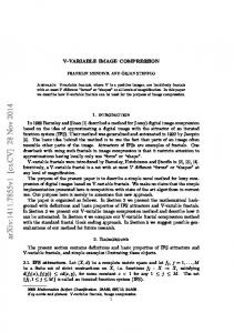
TDC piston position can be regulated by using an unconventional crankshaft in combination with a two-piece connecting rod, which is controlled by an additional shaft, or by using a rack-and-pinion gear for the transmission of power from the piston to the crankshaft. Alternatively, retaining a conventional crankshaft drive, the TDC piston position can be varied by modifying the distance between the crankshaft and the cylinder head or by varying the kinematic effective lengths of the crankshaft drive. The distance between the crankshaft and the cylinder head can be changed by tilting the cylinder head together with the cylinder barrel relative to the bearing pedestals, or by means of a translator mechanism acting on the cylinder head and barrel unit. The required distance change can be realized also by utilizing an eccentrically supported crankshaft. The variation of cinematically effective lengths opens up the widest range of constructive possibilities - compression height, connecting rod length and crank radius can be modified by means of eccentric bearings or by using a linear guidance device. VCR is an old idea, but still not implemented in the realization of larger series. Thus, if we hear now from Infiniti that they have found a solution to incorporate it in the series from 2018, we may perceive it with due scepticism. Here, Atkinson process is used as a way for changing the effective piston stroke. The approach of Infiniti divides the connecting rod into two parts. However, the crankshaft remains as an intermediary of the torque to the flywheel. During the run time of the engine, the angle of the two parts can be changed and, thereby, the connecting rod can be shortened or lengthened. The principle is clearly visible in Figure 5. This engine mechanism promises higher CR (14:1) for fuel efficiency under low load and lower CR (8:1) to aid turbocharging, for more power at higher engine speeds, Figure 5 [44].
Figure 5 Infiniti VCT engines with VCR mechanism Comparison of VCT technology in high (14:1) and low (8:1) compression ratios Because of its classic construction, IC engine can not provide more complete expansion of combustion products in the cylinder. Some researchers have tried to solve this problem. The result is a concept of quasi-constant volume spark ignition engine (QCV SI). In this case, movement of the piston is not linear, because, in this engine, a mechanism forces the piston to move over curve. Piston is moving along a very complex trajectory and this curve is very similar to ellipse [45]. As an example, in the area of transport vehicles and heavy-duty engines, Caterpillar has developed VCR engine for homogeneous charge compression ignition (HCCI) combustion. The result is the 15-liter engine with automatic compression ratio change, from 8 to 15:1. Crankshaft is mounted eccentrically in the cradle, which sits in the cylinder block. Rotating cradle moves the crankshaft, which alters CR [4648]. During research an A engine) was developed, with patented mechanism for the continual change of the CR (CVCR) including two pistons for each cylinder (pistons have relative stroke) for adjusting the cylinder volume, Figure 6. The idea comes from the two-stroke engines with paired cylinders. The position of the paired cylinders is in the form of an A letter, and that is the origin of the patents name. Compression ratio changes with the asynchronous movement of the pistons in the cylinder pair of the engine with two crankshafts. The driving and driven crankshafts are interconnected by the pair of cylindrical gears. The asynchronicity of the pistons in the cylinder pair is controlled by the appropriate regulator, which is mounted on one of the crankshafts [3, 4, 36].
232
Developed VCR engine mechanism can be used in all modern IC engines. In the framework of the EUREKA project led by prof. Pešić, aluminium engine versions were realized [3].
a) b) Figure 6 a) Cross section of “A” engine and b) Photography of main engine parts which made of aluminium
FUEL INJECTION TECHNOLOGY For gasoline engines in passenger cars, the most important task is to improve fuel efficiency. Therefore, a big variety of different technologies potentially can be applied. The system ranges from simple variable charge motion and low cost variable valve timing devices up to high sophisticated systems like fully variable valve actuation systems and combustion with auto ignition HCCI. Direct gasoline injection (DGI) systems of generation 1 (wall guided systems) and even more the systems of generation 2 (spray guided systems) improve fuel efficiency, but the significant costs for NOx exhaust after treatment have to be taken into consideration [49]. Due to its full load benefits, homogeneous DGI is a preferred solution for high performance engines as well as in combination with turbocharging for downsizing concepts. The combination of turbocharging, direct injection and cam phase shifter has proven to be a highly attractive package combining good fuel economy with fun to drive. Different gasoline engines technologies will have to be applied according to the specific needs of their application and brand specific requirements. Even keeping high performance characteristics, fuel consumption will continuously be reduced and future legislative limits can be met. However, system complexity and cost will increase.
Spray guided DGI combustion systems The very first DGI concepts, developed even before the wall and the air guided systems, featured a close spacing between injector and spark plug, Figure 7. However, at that time, such systems were still handicapped by insufficient injection technology. Now these systems are recovering their importance due to the significant progress in fuel injection technology. The close spacing results in excellent stratification capability and higher fuel efficiency improvement compared to alternative concepts [49]. Both stratification injection and mixture formation are largely controlled by the injector itself. Due to the small distance between the injector and the spark plug, the time available for mixture formation is significantly reduced. Consequently, the requirements for the injector are higher than with wall or air guided systems. With conventional spark ignition, the spark has to be arranged in the rim zone of the injection spray to avoid spark plug fouling. Consequently, the spray shape, especially the spray angle, has to be kept largely constant under all engine operation conditions and thus independent from injection timing and the respective backpressure. As a consequence, swirl injectors, as widely used for generation 1 systems, are not a preferred solution for spray guided systems with conventional spark ignition. Injectors such as piezo injectors currently provide specific advantages in mixture formation and application.
233
Combustion chamber geometry as well as charge motion can be designed with much less compromises concerning full load requirements and piston weight than with generation 1 combustion systems.
Exhaust
Injector
Spark plug
Intake
Figure 7 Arrangements for spray guided DGI combustion systems However, the central arrangement of the injector usually requires much more significant modifications of the existing cylinder head designs than only adapting a base MPFI cylinder head towards a wall guided DGI variant. The central position of the injector also raises injector tip temperatures and consequently deposits formation risk at the injector. Both deposit formations as well as spark plug durability are major development issues. As a future alternative, laser induced ignition might be an attractive alternative, Figure 8 [49]. As the ignition point is only determined by the focus of the respective lens and not by the protrusion of the spark plug, the ignition point can be directly set within the main spray cone. Thus, from the viewpoint of reliable ignition, even swirl injectors would be a feasible solution. Currently, such ignitions systems just have proven principal function at a research level and still require significant further development efforts. Alternative combustion systems, such as AVL CSI concept, may become option for lean combustion without need of expensive DeNOx after treatment device, probably in combination and addition to variable valve train systems. Apart from that, the entire automotive world is looking for other alternatives like Hybrids and Fuel Cells. The future will tell whether these alternatives will be able to compete with conventional powertrains.
Figure 8 Laser ignition with spray guided DGI
EXPERIMENTAL SETUP The experiments were carried out in the Laboratory for Engines of the Faculty of Engineering, University of Kragujevac (FIN). Single cylinder, four-stroke, air cooled diesel engine, DMBLombardini type 3LD450, was used during experiment (direct fuel injection system, unit pumppipeinjector, injector with four nozzles, 6 kW rated power, bore 80 mm, stroke 85 mm, stroke volume 454 cm3, valve train DOHC, two valves per cylinder) [1]. The geometric value of CR (ε) is varied from 17.5 to 12.1:1 by replacing the pistons with different piston bowl volume (realized by changing the piston bowl diameter from 43 mm to 55 mm), Figure 9. It is well known that the piston bowl geometry design affects the air-fuel mixing and the subsequent combustion and pollutant formation processes in the DI diesel engines. In this paper, all investigations results were solely related to the CR [1]. During experiments, the engine operated with standard diesel fuel with characteristics specified in Table 2 [1]. 234
Table 2 Fuel characteristics Description Cetane rating (CN) Specific density at 20 °C, (g/cm3) Kinematic viscosity at 20 °C, (mm2/s) Sulphur content (%)
Values 52 0.839 3.964 0.5
The test rig is equipped with the measuring and data acquisition system, Figure 10. Various sensors are mounted on the engine to measure different parameters. A thermocouple was installed on the surface of high pressure fuel pipe. A precision crank angle (CA) encoder was coupled with the crankshaft of the engine. The software stores the data of pressures and volumes corresponding to a particular CA location for plotting the indicator diagram curves. The cylinder pressure is measured using the AVL QC32D water-cooled piezoelectric transducer. The signal of pressure is amplified with the Kistler 5007 charge amplifier and it was processed by using the AVL IndiCom Indicate Software Version 1.2. The software provides the facility for analysing the combustion data, such as the rate of heat release, ignition delay, combustion timing in degrees and peak pressure and stores them separately for analysis in the acquisition system [1]. The experimental engine is tested on the SCHENK U116/2 engine dynamometer. Tests are carried out for CR values of 12.1, 13.8, 15.2 and 17.5:1. Working regimes for fuel consumption and exhaust gas analyses are defined according to the European Stationary Cycle (ESC) 13 mode cycle. Analysis of the combustion process is performed for the operating regime shown in Table 3 [1]. Table 3 Working regimes for combustion analysis Engine speed, Mass of fuel per BMEP, MPa rpm cycle (mg/cycle) 0.12 7 0.24 10 1600 0.36 13.5 0.48 18
Figure 9 Pistons before experiments (the values of the geometric CR for different diameters and volume of the combustion chamber in the piston head)
Figure 10 Schematic diagram of the experimental setup
Exhaust emission is analysed with AVL Dicom 4000 measurement equipment. Particulate matter (PM) emissions are determined indirectly through the empirical correlation between the measured values of smoke and PM. The smoke is measured using the AVL 409 equipment according to BOSCH method. Specific emission of exhaust gases is calculated using the obtained data of exhaust emission and measured engine power at corresponding working point. The final emission results are expressed in gkW–1h–1 [1].
RESULTS AND DISCUSSION Modelling the combustion process of diesel engine having VCR The combustion characteristics can be compared by means of cylinder gas pressure, rate of heat release, ignition delay, etc. The normalized heat release rate (NHRR) or differential combustion law is an important parameter for analysis of the combustion process in the cylinder, Figure 11.a. The important combustion process parameters, such as combustion duration and intensity, can be easily estimated from the rate of the heat release diagram, Figure 11.b [1]. 235
a)
b)
Figure 11 a) Normalized rate of heat release during combustion and b) Combustion process in DI diesel engine In analysed engine regimes, the ignition delay period is too long when the engine works under lower CR value. The longer ignition delay period results in higher proportion of the injected fuel remaining unburned. The large accumulation of unburned fuel during the ignition delay period leads to a characteristics sharp peak, Figure 11.a. At moderate decrease of CR at higher loads (BMEP=0.48 MPa), the decrease of maximal cylinder temperature occurs, Figure 14. During further decrease of the CR, the maximal temperatures start to increase. Explanation is found in considerable increase of the combustion law maximum due to the increased ignition delay, Figure 12.a, induced by lower temperatures at the fuel injection timing. It leads to the increased amount of fuel burned during premixed combustion [1]. At low loads (BMEP=0.24 MPa), when the CR decreases, maximal values of the combustion law continually decrease, Figure 11.a, which reflects in the reduction of maximal cylinder temperature values [1]. In diesel engine, cylinder pressure depends on the burnt fuel fraction during the premixed burning phase, that is, initial stage of combustion. Cylinder pressure characterizes the ability of the fuel to mix well with air and burn condition. The experimental engine has an old fuel injection system with low injection pressure. Since no new injection system was available, it was decided to do the testing with the existing fuel injection systems. Therefore, all the results have been obtained with a low injection pressure. Vibe function is one of the most famous equations or functions used for modelling the combustion process in IC engines. Vibe function is often used to approximate the actual heat release characteristics of an engine. Integral of the Vibe function gives the fraction of the fuel mass that has been burned since the start of combustion. In this paper, the methodology of modelling combustion process is described, with purpose to see how the working regimes and CR value affect the double Vibe function parameters. If operation process of diesel engine with DI and premixed combustion is modelled, the use of double Vibe function is necessary.At DI diesel engines with distinct explosive combustion and diffusive combustion, a model based on one Vibe function cannot describe the characteristic form of the combustion process. In that case, it is necessary to use a model based on superposition of two Vibe functions; one simulating the explosive part (index “1”), the other simulating the diffusive part (index “2”), Equations (1) and (2), Figure 11.b [1, 50, 51]. m 1 1 C 1 z1 x1 g 1 e
m 1 2 C 2 z 2 x 2 (1 g ) 1 e
dx1 g C (m1 1) 1 z1 d 1 z1 dx2 2 d z2
m1
e
C 1 z1
(1 g ) C (m2 1) 2 z2
m1 1
(1)
m1
e
C 2 z 2
m2 1
(2)
Double Vibe function is expressed as the sum of the first and second part of the Vibe function:
x x1 x2
and
dx dx1 dx2 , d d d
where: 236
(3)
𝑥 cumulative normalized heat released (mass fraction burned); 𝛼 crank angle, CA; m1, m2 Vibe function shape parameter (for first and second function part); 1, 2 angle between initial and current time of the first and second Vibe function; z1, z2 duration angle of the each simple Vibe function (duration of the heat release); C Vibe function parameter (𝐶 = 6.908); and g share of fuel mass burnt during the first Vibe function (explosive combustion).
In order to establish the influence of the CR on the parameters of double Vibe function, corresponding experimental and theoretical investigations of the diesel engine with CR change were performed. The research results are shown in Figure 12. As it can be seen, a good match between the model and experiment is achieved [1]. Variation of the identified combustion process parameters is presented in Figure 13, as function of the CR. The increase in CR at constant engine speed and load results in significant decrease of the Vibe function coefficient, Figures 13.a and 13.b [1]. The tests have shown that duration angle of the first explosive part of the combustion is nearly constant, Φz1=9o CA, and this value remained the same during modelling. The total duration angle of combustion, Φz2=Φ, increases with the increase of CR, Figure 13.c. It is the consequence of the larger amount of fuel combusting with diffusive combustion, as shown in Figure 12.a [1]. The amount of the fuel burnt at the first explosive part of first Vibe function, σg, significantly decreases with the increase of the CR by constant amount of the injected fuel and constant engine speed, Figure 13.d. It is also connected to a shorter period of ignition delay at higher CR [1].
Figure 12 Experimental and theoretical rate of heat release diagrams under full load, BMEP=0.55 MP and fixed fuel injection angle (pu). (αps1 and αps2) are angle of initial (start) of combustion (2% of burned mass) for the first and second Vibe function respectively [1]
237
a)
d)
b)
e) Angle of initial (start) of combustion (αps) under constant fuel injection timing (αpu=18,5o CA), intensively increases with the increase of the CR, due to shorter period of ignition delay, which is a consequence of higher maximal temperatures at the moment of fuel injection, Figure 13.e. All tests were performed with experimental engine and conventional fuel injection system. Injection pressure was 20 MPa.
c) Figure 13 Model parameters variations as functions of the CR [1]
Optimal values of the compression ratio The maximal pressure in cylinder (pmax) and exhaust gas temperature (Texhaust) as the function of engine load (Wespecific effective work) for different CR values are shown in Figure 14 [1]. With the increase of CR and engine load, under the same injection timing (18.5o CA) before top dead centre (BTDC), pmax is increasing, too. This undesirable increase in pmax is followed by a relatively improved atomizing of larger amount of fuel in cylinder under higher pressure and engine temperature. Because of the improved conditions for combustion process, the entire working process is improved. Moreover, when the CR is increased, the Texhaust value is decreased, Figure 14, as revealed by simple isentropic relation at high CR. Similar results can be seen in [36]. Leaner air-fuel mixture is used in engine operation under low loads. Therefore, the amount of heat released during the combustion process is decreased. Also, the relatively low fuel injection pressure, which is very poorly dispersed, leads to the existence of large droplets of fuel. A consequence of this is certain decrease in temperature of the engine parts and decrease in cylinder temperature in the first phase of fuel injection. There is also an overlap of Texhaust under middle CR values for all load regimes [1]. Dependence between the brake specific fuel consumption (BSFC) and the CR is presented in Figure 15, for optimal injection time, in various load conditions [1].
238
Figure 14 Cylinder pressure and exhaust temperature change in experimental diesel engine [1] The increase of the CR results in less intensive increase of the BSFC at low loads, and then, it more intensively increases for CRs above 14:1, Figure 15 [1]. At high loads, the BSFC first decreases and reaches the minimum value for CR near 15:1, and then starts to grow again with further increase of CR, Figure 15. The increase of the engine speed causes the increase in the mechanical and aerodynamic losses and the increase in BSFC, Figure 16. The combustion process is responsible for the increase of the fuel consumption. This is obvious in the case of a combined application of low CR and shortened injection timing, when the delay of ignition becomes longer, and, because of that, the combustion process is prolonged to expansion stroke. This is followed by a decrease in pmax and temperature within a cylinder, while temperature during an expansion process shows a tendency to increase. Because of that, the losses become greater and this may be followed by an increase in the BSFC [1].
Figure 15 Influence of the CR on BSFC [1] The optimal value of the CR, at which the engine has minimal BSFC, increases with the increase of the load, Figure 16. At full load, minimal fuel consumption is achieved with ε=17.5, while at low load conditions, minimal fuel consumption is achieved with ε=12 [1]. 239
Figure 16 Selection of the CR optimal value for engine operation with minimal fuel consumption Under low and medium loads, the emission of NOx increases with the increasing of the CR, Figure 17. At high loads, the NOx emission firstly decreases and then increases with the increasing of the CR, and reaches its minimal value with ε=15, Figure 18. Under higher loads, minimal NOx emission is reached with ε=15, Figure 19.
Figure 17 Influence of the CR on NOx emission
Figure 18 Selection of the optimal value of the CR for engine operating with the minimal NOx emission
Figure 19 Influence of the CR on particles emission
Figure 20 Selection of the optimal value of the CR for engine operating with the minimal PM emission
In the case of the largest value of the CR under all loads, the largest temperature occurs inside the engine cylinder. Large amount of free oxygen under low loads, in spite of relatively low maximal temperature with respect to full 240
load, leads to formation of the largest amount of NOx. NOx emission decreases with load increase, under higher CR values. In the case of the lowest value of the CR under low loads, the lowest maximal temperature is achieved within the working cycle. This leads to formation of the lowest amount of NOx. With an increase in load, temperature also increases and the amount of free oxygen decreases. Thus, at the beginning of the process, the amount of produced NOx increases, but, when the amount of free oxygen decreases, a decrease in the amount of produced NOx would occur with load increase [1]. Particulate matter (PM) emission is the smallest at medium loads and it increases if the engine is running at low or high loads. At the same time, PM emission increases with the increase of CR at all loads, Figure 19, so optimal CR is ε=12, Figure 20. Generally, under very low loads, the PM emission is somewhat larger. The major reason for this is a relatively low injection pressure of the small amount of fuel that does not atomize so well. As the amount of fuel increases with a load increase, this effect is attenuated and a certain decrease in PM emission occurs, so that, under large loads, it would begin to increase again. Since the combustion chamber volume increases if the CR decreases, the amount of air in the cylinder increases, and it is the cause of decreasing of PM emission when the CR decreases [1]. Analysis of universal diagrams shows that the trends of CR variation are almost equal for the same values of fuel consumption and emission. Optimal NOx emission is achieved by later injection, while the minimal consumption and PM are achieved by earlier injection. The multiple injection strategies in combination with EGR offer the potential to improve the compromise between engine emissions, noise and fuel economy in diesel engines with lower CR.
ONE ENGINE ANY FUEL AS FUTURE SCENARIO According to law of nature, there are no neither pure energy forms, or “pure fuels”, or “clean engines”, nor “clean vehicles”. All existing reserves such as coal, petroleum and gas are gifts of nature and must be economized not only as power sources but as unique and sole raw materials. Rational technologies and economical utilization of these gifts of nature are the only ways to extend life on our planet. Future vehicles with flexible Otto/diesel engine cycle coupled with the alternative fuels will be key option in development of future transport in the world as well as in the Republic of Serbia. Future vehicles should be optimized according to working process software by sensors and with systems of fuel injection, Figure 21.a. Optimistically defined terms of reference as a symbiosis of superior economy is targeted, which have the best diesel engines with the best environmental attributes Otto engines. In a limited development period, fuel mass will be no more of oil origin. On the other hand, well-known technologies of alternative fuels indicate the economical production of sufficient components as an additive of synthetic origin or from natural gas from any bio-raw materials. After identical logic, earlier fuels for Otto and diesel engines are coupled into one universal fuel. Indeed, we have perceived such a futuristic project tasks [6]: One engine for all fuels and One fuel for all engines. Multi-process IC engine, Figure 21.b, is running with VCR, as Otto engine, the fuel is added with alcohols (octane number over 100) as an additive to raise the octane number (premium gasoline having EU 95). Analogously, when the multi-process engine is running with VCR, as diesel engine, then the additives are bio-diesel oils (cetane number 80) to raise the cetane quality of fuel (Diesel standard have about 50 cetane)! Present refineries have their own consumption of 10 to 15% of the total volume of refined oil, depending on the raw material and on what kind of fuel they produce. If IC engines with VCR (type DieselOtto) are introduced, then there would no longer be a share in the "gasoline" and "diesel” fuel. Large tankers, which transport fuel, directly use purified oil. Only a defined energy and environmentally friendly fuel has its thermal power. Then, there are the disposable complexes as "octane" or "cetane index" numbers and, therefore, a complicated oil refineries, for "highoctane gasoline", with a "high cetane for the diesel" and the like. Refiners should be less spending and more producing and providing energy and environmental quality fuel.
241
a) b) Figure 21 Multi-process multi-fuel IC engine with VCR: a) One engine any fuel concept and b) Future formulation of the fuels for VCR engines with Ottodiesel combustion process
CONCLUSIONS The following generalized conclusions can be written from the study performed during experimental work and presented modelling: VCR engine offers the potential to increase combustion efficiency and decrease emissions under varying load and speed conditions; A good agreement between the model and experimental combustion law of the characteristic shape developed precisely for direct injection diesel engines is achieved by modelling with double Vibe function; Initial combustion angle (αps) intensively increases with the increase of the compression ratio due to shorter period of ignition delay, which is a consequence of higher temperatures at the of fuel injection time. This research has shown that the duration angle of the knocking combustion part is nearly constant and this value remains the same during modelling. Total combustion duration angle increases with the increase of the compression ratio, because the combustion is of higher quality and equally divided through all stages; The amount of fuel burnt at the first stage significantly decreases with the increase of the compression ratio, by constant amount of injected fuel and constant engine speed. This is also connected with shorter duration of ignition delay at higher compression ratios; Value of optimal compression ratio, at which the engine runs with minimal fuel consumption, increases with the increase of load. At full load, the fuel consumption is the smallest at maximal compression ratio of 17.5:1, while at low loads, minimal fuel consumption is achieved for compression ratio 12:1; Under lower compression ratio of 12.1:1, the engine has started very difficultly, and operation continued with higher knocking; From the aspect of minimal NOx emission, optimal compression ratio at full load has a value of 15:1. Particulate matter emission is the smallest for medium loads and it increases if the engine runs at low or high loads. At the same time, particulate matter emission increases with the increase of the compression ratio, so the optimal compression ratio is 12:1; Future vehicles with flexible Otto/diesel engine cycle coupled with the alternative fuels will be key option in development of future transport in the world as well as in the Republic Serbia; and Optimisticaly defined terms of reference as a symbiosis of superior economy is targeted that has the best diesel engines with the best environmental attributes Otto engines.
ACKNOWLEDGMENTS This paper is a result of the research within the project TR35041 financed by the Ministry of Science and Technological Development of the Republic of Serbia.
242
REFERENCES [1] Milojević, S.: "Analyzing the Impact of Variable Compression Ratio on Combustion Process in Diesel Engines”, Mr Thesis, 2005, University of Kragujevac Faculty of Mechanical Engineering,156 p, [2] Pešić, R., Petković, S., Veinović, S.: “Motor VehiclesEquipment”, University Textbook, 2008, University of Kragujevac, Faculty of Mechanical Engineering and University of Banja Luka, Faculty of Mechanical Engineering, 536 p, ISBN 9789993839200, (in Serbian), [3] Pešić, R.: “ASMATAAutomobile Steel Material Parts Substitution with Aluminum”, Mobility & Vehicle Mechanics (MVM), Vol. 30, Special Edition, 2004, pp 1165, [4] Pešić, R.: “The research in the area of IC enginesLaboratory for IC engines on the Faculty of Mechanical Engineering in Kragujevac”, Monography, 2000, University of Kragujevac, Faculty of Mechanical Engineering, 473 p, (in Serbian), [5] Pešić, R., Davinić, A., Veinović, S.: “One engine for all fuelsone fuel for all engines”, 10th EAEC European Automotive Congress, Proceedings, Paper EAEC05YU-EN01, 2005, Belgrade, pp 110, [6] Pešić, R.: “Automobile SI Engines with minimal fuel consumption”, Monography, Mobility & Vehicle Mechanics (MVM), Special Edition, 1994, (in Serbian), [7] Pešić, R., Veinović, S., Orlović, M., Bebić, O.: “Formulation of ecological fuels and design of economical automotive engines”, Petroleum and Coal, Vol. 37, No. 1, 1995, Slovakia, pp 2228, [8] Milosavljević, B., Pešić, R., Taranović, D., Davinić, A., Milojević, S.: “Measurements and modeling pollution from traffic in a street canyon: Assessing and ranking the influences”, Thermal Science, Vol. 19, No. 6, 2015, pp 20932104. https://doi.org/10.2298/TSCI150402111M, [9] Veinović, S., Pešić, R., Janićijević, N., Dragović, T.: “Fuel Flexible engines: Two and four stroke engines with variable compression ratio”, XI International Symposium on Alcohol Fuels, Vol. 1, 1996, Sun City, pp 5257, [10] Pešić, R., Milojević, S., Veinović, S.: “Benefits and Challenges of Variable Compression Ratio at Diesel Engines”, Thermal Science, Vol. 14, No. 4, 2010, pp 10631073, https://doi.org/10.2298/TSCI1004063P, [11] Gruden, D.: “Varovanje okolja v avtomobilski industriji”, Textbook, 2011, Izolit, Ljubljana, 504 pages, (Translation from the German language: Umweltschutz in der Automobilindustrie, Vieweg + Teubner Verlag, GmbH. Wiesbaden, 2008.), [12] Milojević, S., Pešić, R.: “CNG buses for clean and economical city transport”, Mobility & Vehicle Mechanics (MVM), Vol. 37, No. 4, 2011, pp 5771, http://www.mvm.fink.rs/Journal/Archive/2011/2011V37N4/4_sasa_ milojevic/milojevic_pesic_rad.pdf, [13] Milojevic, S., Pesic, R.: “Theoretical and experimental analysis of a CNG cylinder rack connection to a bus roof”, International Journal of Automotive Technology, Vol. 13, No. 3, 2012, pp. 497503, https://doi.org/10.1007/s12239-012-0047-y, [14] Milojević, S.: “Reconstruction of existing city buses on diesel fuel for drive on Hydrogen”, Applied Engineering Letters, Vol. 1, No. 1, 2016, pp 1623, [15] Milojevic, S.: “Optimization of the Hydrogen System for City Busses with Respect to the Traffic Safety”, Proceedings of the 20th World Hydrogen Energy Conference WHEC 2014, Vol. 2, 2014, pp 853860, [16] Milojević, S., Ilić, N., Pešić, R.: “Application of Hydrogen as alternative fuel for propulsion systems in city buses Overview”, Mobility & Vehicle Mechanics (MVM), Vol. 40, No. 3, 2011, pp 6984 [17] Milojević, S.: “Sustainable application of natural gas as engine fuel in city buses – Benefit and restrictions”, Journal of Applied Engineering Science, Vol. 15, No. 1, 2017, pp 8188, 2017, doi: 10.5937/jaes15-12268 [18] Pešić, R., Adžić, M., Petković, S., Hnatko, E., Đokić, D., Veinović, S.: “The future is in the environmental engagement of energy.”, Tractors and Power Machines, Vol.16, No. 3, 2011, pp 2431, [19] ACEA European Oil Sequences 2012, http://www.acea.be/images/uploads/files/2012_ ACEA_Oil_Sequences.pdf, accessed on in October 2013, [20] NGV Global, Natural Gas Vehicle Knowledge Base: “Natural gas vehicle statistics”, 2018, New Zealand, http://www.iangv.org/current-ngv-stats/, [21] Hora, S.T., Agarwal, K.A.: “Effect of varying compression ratio on combustion, performance, and emissions of a hydrogen enriched compressed natural gas fuelled engine”, Journal of Natural Gas Science and Engineering, Vol. 31, 2016, pp 819-828, 2016, https://doi.org/10.1016/j.jngse.2016.03.041, [22] Pešić, R., Petković, S., Hnatko, E., Veinović, S.: “Anthropogenic global warming, Kyoto protocol and transport ecology”, Tractors and Power Machines, Vol. 13, No. 3, 2008, pp 4350, (in Serbian), [23] Milojević, S., Pešić, R.: “Logistics of Application Natural Gas on Buses”, CAR 2011 Conference Proceedings, CAR2011_1105, 2011. pp 110, [24] Milojević, S., Pešić, R.: “Logistics of natural gas applications as engine fuel”, Tractors and Power Machines, Vol. 16, No. 2, 2016, pp 6874, (in Serbian), [25] Pešić, R., Veinović, S., Davinić, A.: “Engine characteristics of gaseous fuel”, Scientific meeting with international participation, YUNG 4P 2002, Proceedings, 2002, Novi Sad, pp 2733, (in Serbian), [26] Milojević, S., Pešić, R., Ilić, N.: “The first CNG powered Serbian lowfloor city bus”, 9th International Conference on accomplishments in electrical and mechanical engineering and information technology, Proceedings, 1999, Banja Luka, pp 657662, (in Serbian), 243
[27] Milojević, S., Pešić, R.: “Benefit and restrictions related to the application of natural gas as engine fuel for city buses”, The 13th International Conference on Clean Energy (ICCE2014), 2014, Turkey, pp 902910, [28] Schommers, J., Scheib, H., Hartweg, M., Bosler, A.: “Minimising friction in combustion engines”, MTZ, Vol. 74, No. 78, 2013, pp 2835, [29] Pesic, R., Milojevic, S.: “Efficiency and Ecological Characteristics of a VCR Diesel Engine”, International Journal of Automotive Technology, Vol. 14, No. 5, 2013, pp 675681, https://doi.org/10.1007/s12239-0130073-4, [30] Gruden, D. et al.: “Traffic and environment”, University Textbook, Springer Verlag, 2003, Berlin Heidelberg, [31] Pešić, R., Hnatko, E., Golec, K., Stanojević, M., Veinović, S.: “Thermodynamic and construction measures for radical reduction of fuel consumption in IC engines”, Combustion Engines, Scientific magazine, no. 2007SC2, 2007, Poland, pp 393400, [32] Milojevic, S., Pesic, R., Taranovic, D.: “Tribological optimization of reciprocating machines according to improving performance”, Journal of the Balkan Tribological Association, Vol. 21, No. 3, 2015, pp 690699, [33] Stojanović, B., Milojević, S.: “Characterization, Manufacturing and Application of Metal Matrix Composites. In: Wythers MC (ed) Advances in Materials Science Research”, 30th edn. Nova Science Publishers, New York, 2017, pp 83133, https://www.novapublishers.com/catalog/product_info.php?products_id=63027, [34] Milojević, S., Pešić, R., Taranović, D.: “Tribological Principles of Constructing the Reciprocating Machines”, Tribology in Industry, Vol. 37, No. 1, 2015, pp 1319, http://www.tribology.rs/journals/2015/2015-1/2.pdf, [35] Milojević, S., Džunić, D., Taranović, D., Pešić, R., Mitrović, S.: “Tribological Reinforcements for Cylinder Liner of Aluminum Example Compressors for Brake Systems of Trucks and Buses”, Proceedings of the 15th International Conference on Tribology SERBIATRIB’17, 2017, Kragujevac, pp 251257, [36] Pešić, R., Golec, K., Hnatko, E., Kaleli, H., Veinović, S.: “Experimental engine with flexible Otto or Diesel cycle (VCRvariable compression ratio)”, Innovative Automotive TechnologyIATʼ03, Proceedings, 2003, Koper, Portorož, pp 281290, [37] Pischinger, S., Vittek, K., Tiemann, C.: “Twostage Variable Compression Ratio with Eccentric Piston Pin”, MTZ, Vol. 70, No. 2, 2009, pp 2027, [38] Mathur, B.Y., Poonia, P.M., Jethoo, S.A., Singh, R.: “Optimization of Compression Ratio of Diesel Fuelled Variable Compression Ratio Engine”, International Journal of Energy Engineering, Vol. 2, No. 3, 2012, pp 99101, [39] Reddy, G.A., et al., “Effect of Compression Ratio on the Performance of Diesel Engine at Different Loads”, Int. Journal of Engineering Research and Applications, Vol. 5, No. 10 (part 2), 2015, pp 6268, [40] Stricker, K. Kocher, L. Koeberlein, E. Alstine, V.D., Shaver, M.G.: “Estimation of effective compression ratio for engines utilizing flexible intake valve actuation”, Proceedings of the Institution of Mechanical Engineers, Part D: Journal of Automobile Engineering, Vol. 226, No. 8, 2012, pp 10011015, https://doi.org/10.1177/0954407012438024, [41] Gajarlawara, N., Rao, P.A.G., Murthy, K.M.: “Experimental investigations of effects of cooling/non cooling of EGR on two level of compression ratio in a common rail diesel engine”, Thermal Science, Vol. 19, No. 6, 2015, pp 19952002, [42] Gajarlawar, N., Khetan, A., Rao, P.A.G.: “Investigations of effects of pilot injection with change in level of compression ratio in a common rail diesel engine”, Thermal Science, Vol. 17, No. 1, 2013, pp 7180, [43] Ahn, S., Park, J., Won, J., Kim, H., Kang, I., Cho, Y., Shin, S.: “An analytical FEMbased study of the drawing process of an ultrahighpressure commonrail fuel tube”, Journal of Mechanical Science and Technology, Vol. 31, No. 7, 2017 pp 33893396, https://doi.org/10.1007/s12206-017-0628-9, [44] Infiniti VCTurbo: “The world’s first productionready variable compression ratio engine”, https://kfz-tech.de/Biblio/Benzinmotor/VarVerdichtung3.htm, Accessed on: 31.08.2018., [45] Dorić, J., Klinar, I.: “The realization and analysis of a new thermodynamic cycle for internal combustion engine”, Thermal Science, Vol. 15, No. 4, 2011, pp 961974, [46] Duffy, K., Kieser, A., Mehresh, P., Frieden, D., Rodman, T., Hardy, B., Hergart, C.: “Heavy Duty HCCI Development Activities”, DOE DEER Conference, DOE Contract DEFC2605NT42412, 2006, pp 125, [47] Colle, V., Constensou, C., Dubois, F., Guilly, L.: “Variable Compression Ratio for Future Emission Standards”, MTZ, Vol. 78, No. 4, 2017, pp 2027, [48] Helling, S.U., Ghetti, S., Methfessel, P., Marten, C.: “Variable Compression for Large Engine”, MTZ, Vol. 78, No. 78, 2017, pp 5054, [49] Fraidl, G.K., Piock, W.F., Fürhapter, A. et al.: “Homogene Selbstzündungdie Zukunft der BenzinDirekteinspritzung”? MTZ Motortech Z, Vol. 63, No. 10, 2002, pp 828837, https://doi.org/10.1007/BF03226652 [50] Ghojel., I.J.: “Review of the development and applications of the Wiebe function: Attribute to the contribution of Ivan Wiebe to engine research”, International Journal of Engine Research, Vol. 11, issue 4, 2010, pp 297–312, https://doi.org/10.1243/14680874JER06510 [51] Saša Milojević and Radivoje Pešić.: “Determination of Combustion Process Model Parameters in Diesel Engine with Variable Compression Ratio,” Journal of Combustion, Vol. 2018, Article ID 5292837, 2018, 11 p, https://doi.org/10.1155/2018/5292837.
244
7th International Congress Motor Vehicles & Motors 2018
ECOLOGY VEHICLE AND ROAD SAFETY - EFFICIENCY Proceedings
October 4th - 5th, 2018 Kragujevac, Serbia
[27] Milojević, S., Pešić, R.: “Benefit and restrictions related to the application of natural gas as engine fuel for city buses”, The 13th International Conference on Clean Energy (ICCE2014), 2014, Turkey, pp 902910, [28] Schommers, J., Scheib, H., Hartweg, M., Bosler, A.: “Minimising friction in combustion engines”, MTZ, Vol. 74, No. 78, 2013, pp 2835, [29] Pesic, R., Milojevic, S.: “Efficiency and Ecological Characteristics of a VCR Diesel Engine”, International Journal of Automotive Technology, Vol. 14, No. 5, 2013, pp 675681, https://doi.org/10.1007/s12239-0130073-4, [30] Gruden, D. et al.: “Traffic and environment”, University Textbook, Springer Verlag, 2003, Berlin Heidelberg, [31] Pešić, R., Hnatko, E., Golec, K., Stanojević, M., Veinović, S.: “Thermodynamic and construction measures for radical reduction of fuel consumption in IC engines”, Combustion Engines, Scientific magazine, no. 2007SC2, 2007, Poland, pp 393400, [32] Milojevic, S., Pesic, R., Taranovic, D.: “Tribological optimization of reciprocating machines according to improving performance”, Journal of the Balkan Tribological Association, Vol. 21, No. 3, 2015, pp 690699, [33] Stojanović, B., Milojević, S.: “Characterization, Manufacturing and Application of Metal Matrix Composites. In: Wythers MC (ed) Advances in Materials Science Research”, 30th edn. Nova Science Publishers, New York, 2017, pp 83133, https://www.novapublishers.com/catalog/product_info.php?products_id=63027, [34] Milojević, S., Pešić, R., Taranović, D.: “Tribological Principles of Constructing the Reciprocating Machines”, Tribology in Industry, Vol. 37, No. 1, 2015, pp 1319, http://www.tribology.rs/journals/2015/2015-1/2.pdf, [35] Milojević, S., Džunić, D., Taranović, D., Pešić, R., Mitrović, S.: “Tribological Reinforcements for Cylinder Liner of Aluminum Example Compressors for Brake Systems of Trucks and Buses”, Proceedings of the 15th International Conference on Tribology SERBIATRIB’17, 2017, Kragujevac, pp 251257, [36] Pešić, R., Golec, K., Hnatko, E., Kaleli, H., Veinović, S.: “Experimental engine with flexible Otto or Diesel cycle (VCRvariable compression ratio)”, Innovative Automotive TechnologyIATʼ03, Proceedings, 2003, Koper, Portorož, pp 281290, [37] Pischinger, S., Vittek, K., Tiemann, C.: “Twostage Variable Compression Ratio with Eccentric Piston Pin”, MTZ, Vol. 70, No. 2, 2009, pp 2027, [38] Mathur, B.Y., Poonia, P.M., Jethoo, S.A., Singh, R.: “Optimization of Compression Ratio of Diesel Fuelled Variable Compression Ratio Engine”, International Journal of Energy Engineering, Vol. 2, No. 3, 2012, pp 99101, [39] Reddy, G.A., et al., “Effect of Compression Ratio on the Performance of Diesel Engine at Different Loads”, Int. Journal of Engineering Research and Applications, Vol. 5, No. 10 (part 2), 2015, pp 6268, [40] Stricker, K. Kocher, L. Koeberlein, E. Alstine, V.D., Shaver, M.G.: “Estimation of effective compression ratio for engines utilizing flexible intake valve actuation”, Proceedings of the Institution of Mechanical Engineers, Part D: Journal of Automobile Engineering, Vol. 226, No. 8, 2012, pp 10011015, https://doi.org/10.1177/0954407012438024, [41] Gajarlawara, N., Rao, P.A.G., Murthy, K.M.: “Experimental investigations of effects of cooling/non cooling of EGR on two level of compression ratio in a common rail diesel engine”, Thermal Science, Vol. 19, No. 6, 2015, pp 19952002, [42] Gajarlawar, N., Khetan, A., Rao, P.A.G.: “Investigations of effects of pilot injection with change in level of compression ratio in a common rail diesel engine”, Thermal Science, Vol. 17, No. 1, 2013, pp 7180, [43] Ahn, S., Park, J., Won, J., Kim, H., Kang, I., Cho, Y., Shin, S.: “An analytical FEMbased study of the drawing process of an ultrahighpressure commonrail fuel tube”, Journal of Mechanical Science and Technology, Vol. 31, No. 7, 2017 pp 33893396, https://doi.org/10.1007/s12206-017-0628-9, [44] Infiniti VCTurbo: “The world’s first productionready variable compression ratio engine”, https://kfz-tech.de/Biblio/Benzinmotor/VarVerdichtung3.htm, Accessed on: 31.08.2018., [45] Dorić, J., Klinar, I.: “The realization and analysis of a new thermodynamic cycle for internal combustion engine”, Thermal Science, Vol. 15, No. 4, 2011, pp 961974, [46] Duffy, K., Kieser, A., Mehresh, P., Frieden, D., Rodman, T., Hardy, B., Hergart, C.: “Heavy Duty HCCI Development Activities”, DOE DEER Conference, DOE Contract DEFC2605NT42412, 2006, pp 125, [47] Colle, V., Constensou, C., Dubois, F., Guilly, L.: “Variable Compression Ratio for Future Emission Standards”, MTZ, Vol. 78, No. 4, 2017, pp 2027, [48] Helling, S.U., Ghetti, S., Methfessel, P., Marten, C.: “Variable Compression for Large Engine”, MTZ, Vol. 78, No. 78, 2017, pp 5054, [49] Fraidl, G.K., Piock, W.F., Fürhapter, A. et al.: “Homogene Selbstzündungdie Zukunft der BenzinDirekteinspritzung”? MTZ Motortech Z, Vol. 63, No. 10, 2002, pp 828837, https://doi.org/10.1007/BF03226652 [50] Ghojel., I.J.: “Review of the development and applications of the Wiebe function: Attribute to the contribution of Ivan Wiebe to engine research”, International Journal of Engine Research, Vol. 11, issue 4, 2010, pp 297–312, https://doi.org/10.1243/14680874JER06510 [51] Saša Milojević and Radivoje Pešić.: “Determination of Combustion Process Model Parameters in Diesel Engine with Variable Compression Ratio,” Journal of Combustion, Vol. 2018, Article ID 5292837, 2018, 11 p, https://doi.org/10.1155/2018/5292837.
244