sin Graduate Research Committee. The authors would like to thank Jim Goodman, Andy Pleszkun, Jim Smith and the anonymous reviewers for their useful ...
INSTRUCTION ISSUE LOGIC FOR HIGH-PERFORMANCE, INTERRUPTABLE P1PELINED PROCESSORS Gurindar S. Sohi and Sriram Vajapeyam Computer Sciences Department University of Wisconsin.Madison 1210 West Dayton Street Madison, Wisconsin 53706
A major problem that arises in pipelined computer design is that an interrupt can be imprecise [2, 3]. This problem is especially severe in multiple functional unit computers in which instructions can complete execution out of program order [2, 4]. For a high-performance, pipelined CPU, an adequate solution must be found for the imprecise interrupt problem and means must be provided for overcoming the performance-degrading factors.
Abstract The performance of pipelined processors is severely limited by data dependencies. In order to achieve high performance, a mechanism to alleviate the effects of data dependencies must exist. If a pipelined CPU with multiple functional units is to be used in the presence of a virtual memory hierarchy, a mechanism must also exist for determining the state of the machine precisely. In this paper, we combine the issues of dependency-resolution and preciseness of state. We present a design for instruction issue logic that resolves dependencies dynamically and, at the same time, guarantees a precise state of the machine, without a significant hardware overhead. Detailed simulation studies for the proposed mechanism, using the Lawrence Livermore loops as a benchmark, are presented.
1.1. Background and Previous W o r k The detrimental effects of branch instructions can be alleviated by using delayed branch instructions. However, the utility of delayed branch instructions is limited for long pipelines. In such cases, other means must exist to alleviate the detrimental effects. A common approach is to use branch prediction [5, 6]. Using prediction techniques, the probable execution path of a branch instruction is determined. Instructions from the predicted path can then be fetched into instruction buffers or even executed in a conditional model2, 7, 8]. While the conditional mode of execution will result in a higher pipeline throughput, especially if the outcome of the branches is predicted correctly, a hardware mechanism must exist which will allow the machine to recover from an incorrect sequence of conditional instructions.
1. INTRODUCTION As the demand for processing power increases, computer system designers are forced to use techniques that result in high-performance processing units. A widely used technique is pipelining [1], in which the overall logic of the system is split into several stages with each stage performing a sub-task of a complete task. Considerable overlap can be achieved because each stage can perform a sub-task for a different task. Pipelined CPUs have two major impediments to their performance: i) data dependencies and ii) branch instructions. An instruction cannot begin execution until its operands are available. If an operand is the result of a previous instruction, the instruction must wait till the previous instruction has completed execution, thereby degrading performance. The performance degradation due to branch instructions is even more severe. Not only must a conditional branch instruction walt for its condition to be known (resulting in "bubbles" in the pipeline), an additional penalty is incurred in fetching an instruction from the taken branch path to the instruction decode and issue stage.
Both hardware and software solutions exist to the data dependency problem. Software solutions use code scheduling techniques (combined with a large set of registers) to increase the dependency distance and to provide interlocks [9]. Hardware solutions employ waiting stations or reservation stations where an instruction can wait for its operands and allow subsequent instructions to proceed [ 10]. In a pipelined machine, imprecise interrupts can be caused by instruction-generated traps such as arithmetic exceptions and page faults. An imprecise interrupt can leave the machine in an irrecoverable state. While the occurrence of arithmetic exceptions is rare, the occurrence of page faults in a machine that supports v ~ u a l memory is not. Therefore, if virtual memory is to be used with a pipelined CPU, it is crucial that interrupts be precise. Several hardware solutions to the problem are described in [3]. We are unaware of any software solutions to the imprecise interrupt problem for multiple functional unit computers. A software solution will be extremely difficult, if not impossible. Not only must the software allow for the worst-case execution time for any instruction, it must also keep track of instructions that have completed out of pre-
Permission to copy without fee all or part of this material is granted provided that the copies are not made or distributedfor direct commercial advantage, the ACM copyright notice and the title of the publicationand its date appear, and notice is given that copying is by permission of the Association for ComputingMachinery. To copy otherwise, or to republish, requires a fee and/or specific permission.
27 © 1987 ACM 0084-7495/87/0600-0027500,75
gram order and generate the appropriate code sequence to undo the effects of those instructions. In either case, some hardware support must be provided to maintain run time information.
i FromMemory
I InstructionFetchUnit ,I
1.2. Outline of the Paper In this paper, we treat the problems of dependency resolution and imprecise interrupts simultaneously. Since a hardware mechanism must exist for implementing precise interrupts, why not extend this mechanism to resolve dependencies and allow out-of-order instruction execution? In section 2, we discuss Tomasulo's dependencyresolution algorithm and extend it, giving several variations, so that the cost of implementing it is not prohibitive even for a large number of registers. In section 3, we discuss the problem of imprecise interrupts and present solutions. Section 4 describes a unit that resolves dependencies as well as implements precise interrupts. The precise interrupt and dependency-resolution mechanisms mutually aid and simplify each other. A simulation analysis of the proposed mechanism using several Livermore loops as benchmarks is carried out in section 5. Finally, we discuss how our mechanism might be used to alleviate the degradation due to branch instructions.
i
[
,'
IZ
Res~tBus
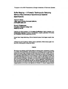
Figure 1. The Basic Architecture cute. Subsequent instructions can proceed if the waiting instruction "steps aside," and allows other instructions to bypass it while it waits for its operanfs. Reservation stations permit an instruction to do this [10]. 2.1. Tomasulo's Algorithm Tomasulo's dependency-resolution algorithm was first presented for the floating-point unit of the IBM 360/91 [10]. An extension of this algorithm for the scalar unit of the CRAY-1 is presented in [13]. The algorithm operates as follows. An instruction whose operands are not available when it enters the decode and issue stage is forwarded to a Reservation Station (RS) associated with the functional unit that it will be using. It waits in the RS until its data dependencies have been resolved, i.e., its operands are available. Once at a reservation station, an instruction can resolve its dependencies by monitoring the Common Data Bus (the Result Bus in our model architecture). When all the operands for an instruction are available, it is dispatched to the appropriate functional unit for execution. The result bus can be reserved either when the instruction is dispatched to the functional unit[13] or soon before it is about the leave the functional unit [10].
1.3. Model Architecture The model architecture that we use for our studies is presented in Figure 1. It has the same capabilities and executes the same instruction set as the scalar unit of the CRAY-1 [4, 11]. However, there is a major difference. In our architecture, all instructions, whether they are composed of I parcel (16 bits) or 2 parcels (32 bits) can issue in a single cycle if issue conditions are favorable. Therefore, the best-case execution time of a conditional branch instruction is 4 clock cycles after the condition is known as opposed to 5 clock cycles for the CRAY-1 [11]. The CRAY-1 was chosen because it represents a state-of-the-art scalar unit and its execution can be modeled precisely. The authors also had easy access to tools that could be used to generate instruction traces for the CRAY-1 scalar unit [12]. The model machine, therefore, consists of several functional units connected to a common result bus. Only one function can output data onto the result bus in any clock cycle. Instructions are fetched by the Instruction Fetch Unit and decoded and issued by the Decode and Issue Unit. Once dependencies have been resolved in the decode and issue unit, instructions are forwarded to the functional units for execution. The results of the functional units are written direct2y into the register file. The register file consists of 8 A, 8 S, 64 B and 64 T registers. DEPENDENCY RESOLUTION: INSTRUCTION EXECUTION
l
File
Functional Units
Throughout the paper, we discuss incremental modifications to the basic principles. Data supporting our claims for such modifications have been omitted for reasons of conciseness. However, we do present detailed simulation data for our final design.
2.
Register
r
Each source register is assigned a bit that determines if rthe register is busy. A register is busy if it is the destination of an instruction that is still in execution. A destination register is also called a sink register [10]. Each sink register is assigned a tag which identifies the result that must be written into the register. Since any register in the register file can be a sink, each register must be assigned a tag. Each reservation station has the following fields:
OUT-OF-ORDER
Source Operand 1
When an instruction reaches the decode and issue stage in the pipeline, checks must be made to determine if the operands for the instruction are available, i.e., if all dependencies for this instruction have been resolved. If an operand is not available, the instruction must wait. Consequently, subsequent instructions cannot proceed even though they may be ready to exe-
28
Source Operand 2
Destination
we associate another bit with each TU entry. This bit indicates if the tag is the latest tag for the register and if the instruction has a key to unlock the register, i.e., clear the busy bit. The modified architecture that incorporates a Tag Unit and reservation stations associated with each functional unit is shown in Figure 2. The reservation stations are modified so that the result can be forwarded to the appropriate slot in the TU. The new reservation station has the following fields:
If a source register is busy when the instruction reaches the issue stage, the tag for the source register is obtained and the instruction is forwarded to a reservation station. If the sink register is busy, the instruction fetches a new tag, updates the tag of the sink register and proceeds to a reservation station. The registers as well as the reservation stations monitor the result bus and update their contents when a matching tag is found. Memory is treated as a special functional unit. Details of the algorithm can be found in [10] and [13].
SourceOperand 1
While this algorithm is straightforward and effective, it is expensive to implement because each register needs to be tagged and each tag needs associative comparison hardware to carry out the tag-matching process. This may not be practical if the number of possible sink fields, i.e., the number of registers is large. For our model architecture which has 8 A, 8 S, 64 B and 64 T registers, clearly the use of 144 tag-matching hardware units is impractical.
Source Operand2
Destination
I FromMemory
I
2.2. Extensions to Tomasulo's Algorithm
InstructionFetchUnit I
On closer inspection we see that very few of all possible sink registers may actually be active, i.e., be waiting for a result at any given time. Therefore, if we associate a tag with each possible sink register, a lot of associative tag-matching hardware will be idle at any given time. Why not have a common tag pool and assign a tag only to a currently active sink register rather than associating a tag with each possible sink field? In Tomasulo's algorithm, a currently active register is one whose busy bit is on.
Register File
I
DecodeandIssueUnit
2.2.1. A Separate Tag Unit
I
'[][], f
stations II~
Functional I Units
We consolidate the tags from all currently active registers into a Tag Unit (TU). Each register now has only a single busy bit. At instruction issue time, if a source register is busy, the TU is queried for the current tag of the appropriate register and the tag is forwarded to the reservation stations. A new tag is obtained for the destination register of the instruction. If the destination register is not busy, acquiring such a tag from the TU is s~aightforward. If the destination register is busy, i.e., the TU already holds a tag for the register, a new tag is obtained and the instruction holding the old tag is informed that, while it may update the register, it may not unlock the register, i.e., clear the busy bit. Instruction issue blocks if no tag can be obtained, i.e., the TU is full.
lIl...II V
ResultBus Figure 2. Issue Logic with a Tag Unit and Distributed Reservation Stations 2.2.1.1. Example The operation of the Tag Unit is best illustrated by an example. Consider a TU that has 6 entries as shown in Figure 3. Each entry in the TU has a bit indicating if the tag is free, i.e., available for use by the issue logic, a bit indicating if the tag is the latest tag for the register and a field for the number of the destination register. The TU is indexed by the tag number. Consider the execution of an instruction 11 that adds the contents of registers SO and $7 and put the result in $4. Assume that the state of the TU is as shown in Figure 3. When the issue logic decodes 11, it attempts to get a new tag for the destination register $4 from the TU and obtains tag 3. Since the TU already has a tag for $4, the old tag (4) is updated to indicate that it no longer represents the latest copy of the register. Since S7's contents are valid, they can be read from the register file and forwarded to the reservation stations directly. However, since the contents of SO are not valid, the latest tag for SO (tag 2) must be obtained from the TU. The issue unit forwards a packet to the reservation station associated with the add functional unit. The packet contains the contents of $7, a tag (2) for SO and a tag (3) for the destination register $4. When I t completes execution, i.e., leaves the add functional unit, the result is forwarded to all reservation stations that have a matching tag (3) and also to the TU. The TU forwards the result to the register
As before, the instruction along with its associated tags/operands is forwarded to a reservation station where it waits for its operands to become ready. The result from a functional unit (along with its tag) is broadcast to all reserva tion stations and is also forwarded to the TU. Reservation stations monitor the result bus and gate in the result if the tag of the data on the result bus matches the tag stored in the reservation station. The TU forwards the result to the register specified in the appropriate slot of the TU. All registers are, therefore, updated only by the TU when their data is available and no direct connection is needed between the functional units and the register file. When the register has been updated by the TU, the corresponding tag is released and is marked free in the TU. In order to ensure correct operation, i.e., only the latest tag for each register is used by all subsequent instructions and only the latest instruction updates the busy bit of the register,
29
Tag Number
Register Number
Tag Free
1
A0
N
2 3 4 5 6
SO NIL $4 SO $3
N Y N N N
reservation station is wasted if it is associated with an instruction that is in a functional unit. However, as we shall see in section 4, this organization can easily be extended to allow for the implementation of precise interrupts. When an instruction issues, it obtains a tag from the RSTU and in doing so automatically reserves a reservation station. All the other functions are as before. Each entry in the RSTU is as follows:
Latest Co Y Y Y Y N Y
Tag Number
r
Figure 3: A Tag Unit file to be written into $4. Since tag 3 is the latest tag for $4, S4's busy bit can be reset when the data has been written into $4. Tag 3 is then marked free, i.e., is available for reuse by the issue logic.
Tag Free
Latest Copy
Source Operand 1
Ir Y°+o II Y+o II R+y i Ta+ i cont II Source Operand 2
Destination
2.2.2. Merging the Reservation Stations 3. I M P L E M E N T A T I O N O F P R E C I S E I N T E R R U P T S
If each functional unit has a separate set of reservation stations, it is likely that some functional unit will run out of reservation stations while the reservation stations associated with another functional unit are idle. As suggested in [13], we can combine all the reservation stations into a common RS Pool rather than having disjoint pools of reservation stations associated with each functional unit. All instructions that were previously issued to distributed reservation stations associated with the functional units now go to the common RS Pool. Instruction issue is blocked if no free reservation station is available, i.e., if the RS Pool is full. As instructions become ready in the RS Pool, they are issued to the functional units. All the other functions are as before.
Now we address the issue of precise interrupts. A complete description of several schemes that implement precise interrupts is given in [3]. The scheme of interest to us is the reorder buffer. The reorder buffer allows instructions to finish execution out of order but updates the state of the machine (registers, memory, etc.), i.e., commits the instructions in the order that the instructions were present in the program, thereby assuring that a precise state of the machine is recoverable at any time. By forcing an ordering of commitment amongst the instructions, the reorder buffer aggravates data dependencies the value of a register cannot be read till it has been updated by the reorder buffer, even though the instruction that computed a value for the register may have completed already.
An organization with merged reservation stations does have one disadvantage over distributed reservation stations only one instruction can issue from the RS Pool to the functional units unless multiple paths are provided between the RS Pool and the functional units. On the other hand, a better use of the reservations stations, results since the reservation stations can be shared amongst several functional units. We chose to provide only a single path from the RS Pool to the functional units because our simulations showed that multiple paths between the RS Pool and the functional units would not have a significant impact on performance. Rather than present detailed simulations to support our decision, we use an argument based on instruction flow to convince the reader. The RS Pool is essentially a reservoir of instructions that is filled by the decode and issue logic and drained by the functional units. Since the decode and issue logic can fill this reservoir at a maximum rate of 1 instruction per cycle, having a drain that is capable of draining more than 1 instruction per cycle will not be very useful in a steady state.
An alternative to a simple reorder buffer is to associate
bypass logic with the reorder buffer. In such an organization, an instruction does not have to wait for the reorder buffer to update a source register; it can fetch the value from the reorder buffer (if it is available) and can issue. With a bypass mechanism, the issue rate of the machine is not degraded considerably if the size of the buffer is reasonably large [3]. However, a bypass mechanism is expensive to implement since it requires a search capability and additional data paths for each buffer entry.
4. M E R G I N G D E P E N D E N C Y R E S O L U T I O N AND P R E CISE INTERRUPTS We note that the R S T U of section 2.2.3 can be modified to behave like a reorder buffer if it is forced to update the state of the machine in the order that the instructions are encountered. This is easily accomplished by managing the R S T U as a queue. Therefore, all that we have to do to implement precise interrupts in an architecture with a RSTU is to manage the RSTU like a queue. The modified logic is called the Register Update Unit (RUU). The RUU is essentially the RSTU constrained to commit instructions in the order that the instructions were received by the decode and issue logic (and consequently by the RUU). The functional units remain unchanged. The modified architecture that uses a R U U to execute instructions out of program order and to ensure a precise state of the machine is given in Figure 4.
2.2.3. Merging the RS Pool with the Tag Unit In the Tag Unit, there is one entry for every instruction that is present in either the RS Pool or in the functional units. Therefore, at any time, there is a one-to-one correspondence between the entries in the TU and the number of instructions in the reservation stations or the functional units. This suggests that we can combine the RS Pool and the Tag Unit into a single
RS Tag Unit (RSTU). In the RSTU, a reservation station is reserved at the same time that a tag is reserved. O f course, a
30
I FromMemory Instruction
intolerable extent. In the next few sections, we describe the components of the RUU in some more detail.
Register File
FetchUnitj 4.2.1. Source Operand Fields I
m RegisterUpdate Unit ],
Functional Units
~
The design of the source operand fields is straightforward. Each source operand field has a ready bit, a tag sub-field and a content sub-field as below:
T Source Operand
I Roady I T.g I Co~e~ I
Load
Registers
If the operand is not ready, the tag sub-field monitors the result bus for a matching tag. If a match is detected, the data on the bus is gated into the content field.
4.2.2. Destination Field
Result Bus
Recall that in the RSTU of section 2.2.3, the issue logic needed to search the TU to obtain the correct tag for the source operand and to update the latest copy field for the destination register. Such a wide associative search may not acceptable because of the large amount of hardware required. If multiple instances of the same destination register are disallowed, no associative logic is necessary. An instance of a register is a new copy of the register. By providing a new instance for a busy destination register, the architecture can process several instructions that write into the same register simultaneously. Unfortunately, disallowing multiple instances of a destination register degrades performance [13]. However, all is not lost. As noted in [10], it is possible to eliminate the associative search and use a counter to provide multiple instances for each register i f we can guarantee that results return to the registers in order. This is exactly the goal of the precise-interrupt mechanism. The implementation of precise interrupts, therefore, simplifies the design of the dependency resolution mechanism.
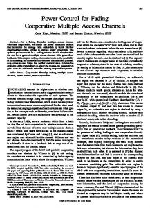
Figure 4. The Modified Architecture with a RUU Note the absence of a direct path between the decode and issue logic and the functional units. In order to implement precise interrupts, every instruction must reserve an entry in the RUU. Since every instruction must pass through the RUU, no direct connection is needed between the decode and issue logic and the functional units. Also note that the CPU's interactions with the memory functional unit have been depicted in more detail. In the next few sections, we describe in some detail the operation of the modified architecture with a RUU.
4.1. Decode and Issue Unit When an instruction is decoded, the issue logic requests an entry in the RUU. If no free entry is available, i.e., the RUU is full, instruction issue is blocked. If an entry is available, the issue logic obtains the position of the entry (an index into the RUU). It then forwards the contents of the source registers (if they are available) or a register identifier (the register number appended with some extra control bits to be used as a tag) to the selected reservation station in the RUU. Control bits for the destination register (a complete description of which follows in section 4.2.2) in the register file are updated and the identifier for the destination register forwarded to the RUU.
The scheme we use associates 2 n-bit counters (control bits) with each register in the register file. There is no busy bit. The counters, the Number o f Instances (NI) and the Latest Instance (LI), represent the number of instances of a register in the RUU and the number of the latest instance, respectively. When an instruction that writes into register Ri is issued to the RUU, both NI and LI are incremented. LI is incremented modulo n. Up to 2 n-1 instances of a register can be present in the RUU at any time; issue is blocked if NI for a destination register is 2n-1. When an instruction leaves the RUU and updates the value of Ri, the associated NI is decremented. A register is free if NI = 0, i.e., there is no instruction in the RUU that is going to write into the register.
4.2. The Register Update Unit The RUU is the unit that (i) determines which instruction should be issued to the functional units for execution, reserves the result bus and dispatches the instruction to the functional unit, (ii) determines which instruction can commit, i.e., update the state of the machine, (iii) monitors the result bus to resolve dependencies and (iv) provides tags to and accepts new instructions from the decode and issue logic. The RUU is managed like a queue using RUU_Head and RUU_Tail pointers. RUU slots that do not lie between RUU_Head and RUU_Tail are free. If RUU_Head = RUU_Tail, the RUU is full and cannot accept any more instructions from the decode and issue logic. In designing the RUU, we keep in mind that (i) it should not involve a large amount of comparison hardware and (ii) it should not affect the clock speed to an
The register tag sent to the RUU now consists of the register number Ri appended with the LI counter. This guarantees that future instructions access the latest instance, i.e., obtain the latest copy of the register contents and that instructions already present in the RUU get the correct version of the data. In our experiments, each of these counters was 3 bits wide. A 3-bit counter ensured that, for our benchmark programs, an instruction never blocked in the decode and issue stage because an instance of a register was unavailable. Since we had a total of 144 registers, the tag field was 11 (8+3) bits wide. There is no need for a Latest Copy field in the RUU and
31
no associative logic is needed to search within the RUU.
If no match occurs for either operation, a free load register is obtained. A load register is free if there are no pending load or store instructions to the memory address held in the load register, i.e., NI = 0. The NI counter is set to 1 and the LI counter is set to 0. The load request is submitted to memory. The corresponding tag is also submitted to memory so that the data supplied by the memory may be read by the appropriate source operands in the RUU. Load/store instructions are not issued by the RUU if a free load register is not available. When the result for a load operation returns from the memory or the store operation is committed by the RUU, NI is decremented. The data and the address are forwarded to the memory in case of a store operation.
4.2.3. Bypass Logic in the RUU One of the primary drawbacks of the simple reorder buffer presented in[3] is that performance may be degraded because instruction issue is blocked if a source register is busy even though its result may be present in the reorder buffer. This performance-degrading problem is easily rectified if bypass logic is provided so that a source operand could be read directly from the reorder buffer before it is written into the register file. Such bypass logic though simple, is cumbersome and expensive to implement. Does the RUU need such logic? Consider an instruction I i that uses the result of a previous instruction lj. Recall that the reservation stations associated with the RUU already have the capability to monitor the result bus. Therefore, if lj completes execution after I i is issued to the RUU, li can gate in the result from lj when it appears on the result bus. In this case, no bypass logic is needed. The only case that bypass logic might be helpful is when lj has completed execution but has not committed, i.e., updated the register file, when I i is issued to the RUU.
Note that decode and issue unit logic needs to search the load registers associatively for memory addresses. However, the hardware needed for this comparison is not very great for a small number of load registers. In our simulations, we used 6 load registers though 4 were sufficient for most cases. 4.4. O p e r a t i o n of the RUU In each clock cycle, the RUU carries out 4 distinct tasks: (i) it accepts an instruction from the issue logic, (ii) it commits an instruction, i.e., updates the register file, (iii) it issues an instruction to the functional units and (iv) it monitors the busses for matching tags. This constitutes a lot of work; however, each of these tasks can be carded out in parallel.
Rather that providing bypass logic for this case, we extend the monitoring capabilities of the reservation stations to monitor both the result bus and the RUU to register bus. This can be accomplished without a substantial increase in hardware. Therefore, I i's dependency on lj is resolved when Ij puts its result on the RUU to register bus iflj has completed execution before li is issued to the RUU. If li is issued to the RUU before lj completes, li's dependency on lj can be resolved when lj completes and puts its result on the result bus. Therefore, instruction I i needs to wait in the decode and issue stage only if the RUU is full.
Accepting a new task is straightforward. If an entry in the RUU is free, the issue logic updates the fields of the selected entry. If the instruction at the head of the RUU has finished execution, its results are forwarded to the register file. If the operands of an instruction in the RUU are ready, the instruction can issue to the functional units. Priority is first given to load/store instructions and then to an instruction which entered the R U U earlier. The R U U reserves the result bus when it issues an instruction to the functional units. The final task of monitoring the busses is left to the tag-matching logic in the source-operand fields. Each entry in the RUU is, therefore:
4.3. Interactions with M e m o r y Instructions that interact with the memory, i.e., load/store instructions, are handled in a special manner. Rather than using Load addresses, a Store data buffer and a Conflict buffer as in [13], we keep a set of Load Registers to resolve dependencies in the memory functional unit. The reservation stations for load/store instructions are provided by the RUU. The load registers contain the addresses of "currently active" memory locations. Each load register has the LI and NI counters to allow for multiple instances of a memory address.
Source Operand 1
Destination
If the address of a load/store operation is unavailable, subsequent load/store instructions in the RUU are not allowed
Source Operand 2
Executed
I Rogis r, I con t II
to proceed. When a load instruction is allowed to proceed, it checks to see if the address for the load operation matches an address stored in the load registers. If a match occurs and the load register is not free (NI is nonzero) the load instruction simply forwards a tag to the RUU. The load operation is not submitted to the memory. The tag is the number of the load register appended with the LI counter. A match can occur if there is either a pending load or a pending store operation. In either case, the load need not be submitted to memory since the desired data can be obtained when the pending load or store operation completes. If a match occurs for a store instruction, the NI and LI counters are incremented and the new tag forwarded to the RUU.
Program Counter
II co ot
I
The Program Counter field is needed for the implementation of precise interrupts [3]. For the sake of brevity, we have omitted the details of extra information that must be carded around with each instruction (such as tags and RUU entry numbers). The details of such information are obvious. 5. S I M U L A T I O N R E S U L T S In order to evaluate the effectiveness of the RUU, we carried out trace-driven simulations. The benchmark programs used for all our simulations were the Lawrence Livermore loops [14]. The first 14 loops were chosen because they were readily available. Henceforth, we shall refer to them as LL1, LL2 ..... LL14. The simulations were carded out as follows.
32
The benchmark programs, as compiled by the CFT compiler for the scalar unit, were fed into the CRAY-1 simulator [12]. The CRAY-1 simulator generates an instruction trace for each program. Vector instructions are not used. Each instruction trace was then fed into our simulator to calculate the execution time and the relative speedup for different RUU sizes. Our simulator converts 2 parcel instructions to 1 parcel instructions when they are encountered.
6. BRANCH PREDICTION INSTRUCTIONS
AND
CONDITIONAL
As mentioned earlier, the performance degradation due to branches can be reduced by conditionally executing instructions from a predicted branch path. Several architectures employ this approach [2, 8, 15]. To allow conditional execution of instructions, a hardware mechanism is needed that would allow the machine to recover from an incorrect branch prediction.
In our simulations, the LI and NI counters were each 3 bits wide thereby allowing up to 7 instances of a register in the RUU. This was useful in loops 7, 8, 9 and 14 which updated the contents of registers frequently. We used 6 load registers so that the issue of a load/store instruction is never blocked because a load register is unavailable. Furthermore, an instruction left the RUU only when it was executed completely. Specifically, load instructions did not leave the RUU for at least 10 cycles after they were issued to the memory (the time taken for the result to come back from the memory). Table 1 presents the speedups for a RUU with bypass logic over a simple CRAY-like instruction issue mechanism[13] for different sizes of the RUU. A speedup of greater than 1 implies that the instruction issue mechanism using a RUU is faster than the simple CRAY-like instruction issue mechanism. Note that the CRAY-like instruction issue mechanism does not implement precise interrupts. The average column is the average for all 14 loops. The results are quite encouraging. A RUU with a reasonable number of entries (8-12), not only speeds up execution, it also provides precise interrupts. We would like to point out that we have assumed that the clock period for our mechanism is the same as the clock period for the simple CRAY-like instruction issue mechanism. Unfortunately, we cannot verify this assumption till a hardware implementation is actually realized. If the clock periods are indeed different, the speedup factors would have to be normalized accordingly.
The RUU provides a very powerful mechanism for nullifying instructions, be the instructions valid instructions or instructions that executed in a conditional mode. Valid instructions may be nullified because of an interrupt caused by a previous instruction; conditionally executed instructions may be nullified if they are from an incorrect execution path. Therefore, the conditional execution of instructions with a RUU is very easy. If the decode and issue unit predicts the outcome of branches and actually executes instructions from a predicted path in a conditional mode, recovery from incorrect branch predictions can be achieved very easily without duplicating the register file. We can identify such instructions through the use of an additional field in the RUU and prevent them from being committed until they are proven to be from a correct path. Furthermore, there is no hard limit to the number of branches that can be predicted in a branch path; the RUU can provide multiple instances of a register for the different paths. This is in contrast to the approach taken in [15]. Extending the RUU to accommodate branch prediction and conditional execution is a topic for future research. 7. CONCLUSION In this paper, we have combined the issues of hardware dependency-resolution and implementation of precise interrupts. We devised a scheme that can resolve dependencies and thereby allow out-of-order instruction execution without associating tag-matching hardware with each register. Such a scheme can, therefore, be used even in the presence of a large number of registers without a substantial hardware cost. Then we extended the scheme to incorporate precise interrupts. The precise interrupt and the dependency-resolution mechanisms mutually aid and simplify each other. We evaluated the performance of the resulting hardware that allows out-of-order instruction execution and also implements precise interrupts using several Livermore loops as the benchmark. The results are quite encouraging. The combined mechanism, called the RUU, is able to implement precise interrupts and is able to
Since bypass logic is expensive, we decided to evaluate a RUU that did not have any bypass logic but its reservation stations monitored both the result bus and the RUU to register bus as discussed in section 4.2.3. The results are presented in Table 2. For many cases, the presence of bypass logic made a negligible difference, if any. On the average, a RUU with no bypass logic is still able to speed up the execution time and, at the same time, implement precise interrupts. The RUU is specially able to speedup loops that make heavy use of the B and T register files (loops 3, 4 and 8). From tables 1 and 2, it may seem that a reasonably large sized RUU is needed to achieve a performance improvement. The main reason for the large RUU size is that, in our simulations, load instructions did not free a slot in the RUU till the instruction was completely executed (10 cycles). Consequently, instruction issue is blocked because of unavailable RUU slots. If, as in [3], we had allowed load instructions to free RUU slots as soon as it was determined that they would not cause exceptions, much smaller RUU sizes would be needed. Even for the presented results we note that an architecture with a RUU of size 10 has comparable hardware requirements to an architecture that associates only a single reservation station with each of the functional units and does not associate any tags with the registers.
achieve a significant performance improvement over a simple instruction issue mechanism without a substantial cost in hardware. We noted that this mechanism can easily be extended to support conditional execution of instructions from a predicted branch path.
Acknowledgments This work was supported in part by the University of Wisconsin Graduate Research Committee. The authors would like to thank Jim Goodman, Andy Pleszkun, Jim Smith and the anonymous reviewers for their useful comments.
33
Table 1: Relative Speedups with Bypass Logic RUU Size Benchmark ' LL1 LL2 LL3 LL4 LL5 LL6 LL7 LL8 LL9 LL10 LL11 LL12 LL13 LL14 Average
4 0.95 0.76 1.00 1.02 0.87 0.81 0.81 0.54 0.70 0.83 0.71 0.93 0.82 0.90 0.85
6 1.04 0.92 1.05 1.13 0.98 1.01 1.10 0.78 0.90 1.01 0.75 1.00 1.09 1.13 0.99
8 1.26 1.04 1.27 1.20 1.19 1.17 1.43 0.93 1.06 1.06 0.93 1.33 1.18 1.31 I 1.17 I
10 12 1.48 1.59 1.20 1.22 1.42 1.76 1.28 1.37 1.26 1.34 1.26 1.34 1.60 1.73 1.04 1.09 1.16 1.22 1.17 1.20 1.03 1.03 1.47 1.55 1.35 11.41 1.38 1.43 1.29 ] 1.37
14 1.78 1.22 1.76 1.78 1.40 1.40 1.84 1.15 1.27 1.20 1.03 1.55 1.50 1.55 1.44
16 1.78 1.22 1.84 1.78 1.44 1.46 1.94 1.16 1.32 1.20 1.03 1.55 1.52 1.83 1.48
18 1.78 1.22 1.94 1.78 1.44 1.49 1.97 1.16 1.42 1.20 1.03 1.55 1.53 1.89 1.50
20 1.78 1.22 2.05 1.78 1.44 1.50 1.91 1.15 1.42 1.20 1.03 1.55 1.57 1.95 1.51
30 1.78 1.22 2.05 1.78 1.44 1.50 1.96 1.24 1.41 1.20 1.03 1.55 1.68 2.06 1.53
50 1.94 1.70 2.05 1.78 2.02 2.04 2.01 1.60 1.80 1.75 1.39 1.69 1.79 2.09 1.81
Table 2: Relative Speedups with No Bypass Logic RUU Size Benchmark LL1 LL2 LL3 LL4 LL5 LL6 LL7 LL8 LL9 LL10 LL11 LL12 LL13 LL14 Average
4 0.91 0.74 1.00 0.97 0.82 0.77 0.81 0.54 0.69 0.83 0.69 0.93 0.82 0.83 0.82
i
6 1.02 0.88 1.05 1.02 0.95 0.93 1.05 0.76 0.88 1.00 0.75 1.00 1.02 0.95 0.94
t
8 10 l 12 1.22, 1 . 3 0 1 . 3 0 1.01 ] 1.17 1.19 1.271 1.42 1.76 1.08:1.14 1.36 1.06 1.10 1.10 1.01 1.06 1.10 1.21 1.26 1.31 0 . 9 1 0.98 0.99 1.04 1.11 1.14 1.03 1.14 1.13 0.93 1.03 1.03 1.33 1.47 1.55 1.16 1.27 1.39 1.05 i 1.04 t 1.07 1.10 1.18 1.25
i
14 1.34 1.19 1.76 1.46 1.10 1.10 1.24 1.05 1.19 1.14 1.03 1.55 1.3~5 1.08 1.26
i
16 1.34 1.19 1.84 1.46 1.10 1.10 1.24 1.06 1.18 1.14 1.03 1.55 1.44 1.20 1.29
i
18 1.34 1.19 1.94 1.52 1.10 1.10 1.27 1.06 1.17 1.14 1.03 1.55 1.45 1.18 1.30
i
20 1.34 1.19 2.05 1.54 1.10 1.08 1.28 1.09 1.19 1.14 1.03 1.55 1.45 1.23 1.31
i
30 50 1.34 1.87 1.19 1.68 2.05 i 2.05 1.47 1.77 1.10 1.90 1.19 2.05 1.62 2.00 1.11 1.56 1.20 1.80 1.16 1.75 1.03 1.39 1.55 1.69 1.39 1.70 1.53 i 1.98 1.35 1.79
References [1]
P.M. Kogge, The Architecture of Pipelined Computers. New York: McGraw-Hill, 1981.
[2]
D.W. Anderson, F. J. Sparacio, and R. M. Tomasulo, "The IBM System/360 Model 91: Machine Philosophy and InstructionHandling," IBM Journal of Research and Development, pp. 8-24, January 1967.
[3]
J.E. Smith and A. R. Pleszkun, "Implementation of Precise Interrupts in Pipelined Processors," Proc. 12th Annual Symposium on Computer Architecture, pp. 36-44, June 1985.
[9]
J. Hennessy, N. Jouppi, F. Baskett, T. Gross, and J. Gill, "Hardware/Software Tradeoffs for Increased Performance," Proc. Int. Symp. on Arch. Supportfor Prog. Lang. and Operating Sys., pp. 2-11, March 1982.
[10]
R. M. Tomasulo, "An Efficient Algorithm for Exploiting Multiple Arithmetic Units," IBM Journal of Research and Development, pp. 25-33, January 1967.
[11]
CRAY-1 Computer Systems, Hardware Reference Manual. Chippewa Falls, WI: Cray Research, Inc., 1982.
[4]
R. M Russel, "The CRAY-1 Computer System," CACM, vol. 21, pp. 63-72, January 1978.
[12]
N. Pang and J. E. Smith, "CRAY-1 Simulation Tools," Tech. Report ECE-83-11, University of Wisconsin-Madison, Dec. 1983.
[5]
J.E. Smith, "A Study of Branch Prediction Strategies," Proc. 8th International Symposium on Computer Architecture, pp. 135-148,
[13]
S. Weiss and J. E. Smith, "Instruction Issue Logic for Pipelined Supercomputers," Proc. 11th Annual Symposium on Computer Architecture, pp. 110-118, June 1984.
[6]
J . K . F . Lee and A. J. Smith, "Branch Prediction Strategies and Branch Target Buffer Design," IEEE Computer, vol. 17, pp. 6-22, January 1984.
[14]
F. H. McMahon, FORTRAN CPU Performance Analysis. Lawrence Livermore Laboratories, 1972.
[7]
P . Y . T . Hsu and E. S. Davidson, "Highly Concurrent Scalar Processing," Proc. 13th Annual Symposium on Computer Architecture, pp. 386-395, June 1986.
[15]
W. Hwu and Y. N Patt, "HPSm, a High Performance Restricted Data Flow Architecture Having Minimal Functionality," Proc. 13th Annual Symposium on Computer Architecture, pp. 297-307, June 1986.
[8]
A. Pleszkun, J. Goodman, W. C. Hsu, R. Joersz, G. Bier, P. Woest, and P. Schecter, "WISQ: A Restartable Architecture Using Queues," in Proc. 14th Annual Symposium on Computer Architecture, Pittsburgh, PA, June, 1987.
May 1981.
34