REM2005 June 30th – July 1st 2005 FRANCE
Integration of V-model and SysML for advanced mechatronics system design R. Sell, M. Tamre Department of Mechatronics, Tallinn University of Technology Address Phone: +372-6203201, Fax: +372-6203203, E-mail:
[email protected]
Abstract – Demands for time, cost and clearness for mechatronics system design process has been significantly increased during last years. At the same time new methods are developed or are under the development to satisfy these needs. This paper represents the integration of two novel approaches for advanced mechatronics system design. A case study is composed.
First draft version of SysML specification is published on the January 2005 and is taken as a basis of this work. The aim of this work is to integrate VDI mechatronics product design lifecycle with new modeling language to give integrated tool for mechatronics engineer. This integrated method is one part of our newly developed approach – Semi-automated mechatronics design methodology. II. MECHATRONICS DESIGN PROCESS IN BRIEF
I. INTRODUCTION A. Design methods, tools and techniques In early stages long product development process and cost consuming prototype building was rather common, comparing nowadays market needs and industry competition. Demands for time and cost for mechatronics system design process has been significantly increased when the cross-domain borders have been, at the same time, blurred. There is hard to find pure mechanical or electrical product on the modern product range. Many daily-used home-equipment are now complicated mechatronics product, capable to interact with other devices in different way. Phone is not a single phone any more, but camera-radio-bank-positioning and so on, device. As there is less time and money for this kind of integrated devices development, new design methods are required to satisfy these needs. This leads us to search new methods, techniques and tools to satisfy the industry and the customer, but meantime not to lose quality and innovation. Most tools and techniques used today are more-less domain specific or have a strong one-domain influence. True domain-independent methods (for example Bond Graphs) are on the other hand too abstract and difficult to apply for full product development life cycle. Continuously growing trend of the mechatronics products is increasing importance of software and its integration with hardware. Therefore it is reasonable to use very similar design concepts for software design as well as overall design on the mechatronics product development. New guidelines for mechatronics design process are developed by VDI (Verein Deutsche Ingenieure). This document exploits well known Vwaterfall model as a design macro-cycle and problemsolving techniques as a micro-cycle. As a modeling technique for system design, new modeling language SysML (System Modeling Language) is under the development. This language is intended to unify diverse modeling languages currently used by design engineers.
There a lot of different techniques and tool to carry through mechatronics design process. Depending on the design process stage and interaction level, in the practice, many different general modeling tools as well as rare and specific tools are used. On the conceptual and system design stage, most widely used technique is block diagram and its different modifications. Also crossdomain conceptual techniques, like Bond Graphs, Petri Nets, etc. are employed. On the domain-specific design stage, much more different methods and tools are used. Every sub-domain of mechatronics has its own settled tools and methods. Most well known on the mechanical engineering domain are: CAD/CAM, FEM, multi-body, Virtual Prototyping, etc. On the electronics system design schematics diagram software, EDA, VHDL and so on is widely used. Control engineering and software design is supported by the CASE tools, UML and different representation of block diagrams. Important role is played by the different type of supporting software like PDM (Product Data Management, BOM (Bill of Material), Project management, Groupware/Workflow, etc. Currently it is common practice for mechatronics systems engineers to use a wide range of modeling languages, tools and techniques on engineering systems projects. To unify different domain specific- as well as cross-domain modeling technique a new approach - System Engineering Modeling Language, based on the renewed UML 2.0 specification is under the development. On the other hand, VDI method is a perfect guideline to integrate it with a SysML language, giving a contemporary tool for mechatronics engineer. Both are developed by industry consortiums and reviewed by specialists from public, corresponding in such a manner very well for today’s industry needs.
page
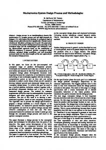
REM2005 June 30th – July 1st 2005 FRANCE B. V-model from VDI 2206 The latest and probably the widest coverage guidelines: Design methodology for mechatronical systems; have been developed by German Association of Engineers (VDI) in 2002 and revised on May 2004. This guideline presents the most recent point of view and has been worked out by 40 well-known specialists in the field of mechatronics. In the VDI 2206 guidelines the design methodology main base elements are: the general cycle of problem solving on the microlevel, the V-shape model on the macro-level, pre-defined process modules for recurrent working steps. The main aim of this guideline is to support a crossdomain design of a mechatronical system in a systematic way. On the micro-level general well proved problem solving cycle is proposed. It has been adopted in modified forms from other disciplines like software engineering and business management. On the macro-level the V-shape model for describing mechatronic design process is exploited (Fig 1.). The model is based on the traditional waterfall process model but has a set of useful properties in description in the sense that relations between different design stages can be easily illustrated [VDI, 2004]. The design cycle starts with conceptual stage which consists of requirements specification and situation analyses. The result of this is a design specification and a clearly formulated set of desired measurable behaviors of the future product, which introduces the quality measure into the design process. System design continues conceptual design and specifies system architecture, functions and behavior in different levels.
Fig. 1. V-shape model [VDI, 2004]
This is cross-domain design and takes into account overall system requirements and goals. On the bottom of V-model domain specific design is carried out. As the results of domain specific design system integration must be performed to put it all together as it was defined in the beginning. During the product development process, continuous check of accordance of the requirements and solution concept must be performed to ensure that the actual system properties coincide with the desired system properties. The outcome of one cycle is the product. Depending on the cycle level the product might represent from 3D model to ready to marked product or detail specification, etc. A complex mechatronics product is generally not produced within one macro-cycle [VDI, 2004]. C. System Modeling Language (SysML) SysML is a general-purpose modeling language for systems engineering applications that is being supported by a wide range of industry leaders, government agencies and tool vendors. SysML is designed to provide simple but powerful constructs for modeling a wide range of systems engineering problems. It is particularly effective in specifying requirements, system structure, functional behavior, and allocations during specification and design phases of systems engineering. SysML is being aligned with two evolving interoperability standards: the ISO AP233 data interchange standard for systems engineering tools and the OMG XMI 2.0 model interchange standard for UML 2.0 modeling tools [SysML, 2005]. D. Integration of SysML and V-model Principles of the mechatronics design methodology, developed by VDI is a widely accepted in mechatronics product development domain. UML language is de facto standard in software world. All mechatronics products have constantly growing software parts, and therefore it is important to improve the understanding between software designers and mechatronics engineers through the whole product design lifecycle. The SysML language is good bridge between software- and hardware design and integrating this with widely accepted and well understood mechatronics design methodology is essential for effective design process. Main benefits of this approach are: • good understanding between software and system engineers (SE), • robust and extensible language to adapt to SE needs, • OMG Infrastructure, • support of quality assurance through the whole design process, • availability of tool vendor and training support, • system overview on every stage, • cross-domain nature and compatibility with existing techniques.
page
REM2005 June 30th – July 1st 2005 FRANCE III. INTEGRATION PRINCIPLES
B. Interactive Design
A. Design Cycle A design cycle of V-model, from VDI, consists of requirements, system design, domain-specific design, integration and product part. This initial decomposition is changed and result is seen on the table I. Design stages are adjusted as followings: conceptual design, system design and integration. Every stage has a set of suggested diagrams from SysML on particular detail level (table I). Although here, only SysML tools are described, all other engineering techniques like CAD/CAM, FEM and other CAE system are not excluded. Creating 3D models or running different kind of calculations are definitely suggested, as SysML language are not meant for these tasks, but rather to model overall system on abstract level. Table I level description: C1 – Class level 1, system and subsystems hierarchy. C2 – Class level 2, components and subcomponents hierarchy (if required part layer can be also added). R1 – Requirement level 1, initial requirements specified by customer. R2 – Requirement level 2, changed/optimized requirement list and supplemented rationale and verify conditions. A1 – Assemblies level 1, system composed by subassemblies. A2 – Assemblies level 2, assemblies and subassemblies decomposed by parts and ports. TABLE I DIAGRAM TYPES AND DESCRIPTIONS Diagram Description CONCEPTUAL (requirements, system concept) Class Hierarchical abstraction of system and his components on conceptual level. Use Case System main functionality and services for particular stereotyped user and/or environment. Requirements Requirement list for functionality, performance, structure, etc. Verify, satisfy and trace conditions for particular requirement. Assemblies Modular structure of the system. System architecture DESIGN (system design, domain-specific design) Class Sub-components hierarchy Assemblies Logical and physical decomposition of system structure Activities Analogous for EFFBD (Enhanced Functional Flow Block Diagram) Sate Machine Discrete behavior (through the final states) of the system. Modeling activities, states and messages. INTEGRATION (integration, product evaluation) Parametric Properties and constraints of the system. Parametrical relations. Timing Changes in time, related with states, parameters or activities. Sequence Methods of operations triggered by messages.
A final product is generally not produced with one single cycle. On this approach three main cycles are distinguished, although this may expanded or merged as design process requires. Depending on the complexity of the design problem the main cycle may divided into subcycles. Initial requirements definition and design problem formulation are the starting points of the first cycle. The product is a full system specification and this is also an input for next cycle. Following cycle ends with prototype of product or laboratory specimen. Last cycle will produce tested and verified final product. Inside of one cycle the assurance of properties (accordingly VDI guideline) is continuous process to ensure their conformity for initial requirements. I cycle – System specification SysML diagrams will be generated accordingly table 1. Main parameters as a result of problem definition will be arranged. If specified by customer, testing and verification procedures are included into initial diagrams. Tools: UML/SysML editor, CAD, Mechatronics software II cycle – Prototype On the prototype cycle, all diagrams created during last cycle will be concretized and additional elements will be added as new aspects or modifications are raised. More precise testing and verification procedures and rules will be added. Besides of SysML diagrams CAD/CAM models and drawings will be generated and analysis of different aspects is carried out. Tools: additionally for previous cycle, BOM
Level C1
R1 (R2)
A1
C2 A2
II cycle – Product All SysML drawings will be adjusted again. Final verification and testing rules will be added. Parameters for different diagrams will be added or adjusted as a result of prototype testing. Tools: additionally for previous cycle, CAM Ideally, models of later cycle are built up on models of earlier cycle. Models describing different aspects, like behavior, functions, etc. of a system, must take into account each other so, that they can be universally interconnected. C. Compatibility The important feature of every technique at present days is its compatibility with other design techniques and tools. As SysML has the mapping concept with AP233 / ISO 10303 STEP and Express models the whole approach has a built in data exchange feature with other engineering tools. From software side, the SysML is an extension of UML 2.0 specification and inherit all necessary features and compatibility.
page
REM2005 June 30th – July 1st 2005 FRANCE
IV. CASE STUDY A. Problem description A design aim of this Case Study was to develop an UGV (Unmanned Ground Vehicle) universal platform. Initial requirements were discussed with customer and initial requirement document was compiled. Basic items from requirement document: ⎯ UGV must be teleoperated and semi-autonomous ⎯ Payload ~50Kg ⎯ Universal modular architecture for various tasks ⎯ Equipped with different video cameras + night vision ⎯ Reliable for different weather conditions ⎯ More precise definitions were set for: moving equipment, energy consumptions, dimensions, control system, payload, communication, manipulator and operator interface. Design time was set to 1 year. On the project definition and planning phase following actions was taken: ⎯ Formulation of project team and its competence. ⎯ Requirement analysis and compilation through the several meetings and discussions with customer and experts. ⎯ Project planning and cost estimation. ⎯ Changes management rules. B. Conceptual Design On the conceptual design, basic steps (according Ullman [Ullman, 2003]) were followed and four main solution candidates were generated. On the modeling point of view SysML models were generated (Fig. 2) and 3D CAD models was used to visualize different principles.
Following models were generated accordingly developed method described last chapter: ⎯ Requirement diagram, describing requirement states a capability or condition that the system must satisfy (Fig. 2.), ⎯ Class diagram, describing system hierarchy on the main component level. ⎯ Use Case diagram, describing expected behavior of the system (Fig. 3.), ⎯ 3D CAD models, visualization purpose and describing design candidate’s structure. Additionally, basic calculations and cost estimation was carried out to evaluate different solutions. A requirement on the requirement model (Fig. 2.) states a capability that a system must satisfy. Here additional subtypes of requirement stereotypes (PerformanceRequirement and StructuralRequirement) are defined. Requirements are defined by their properties, providing thereby computational value to accompany the textual statement of requirement. On this example one ‘testCase’ is defined, which is a guideline that is used to determine whether a system has fulfilled its requirements. Use Case diagram (Fig. 3.) is describing the system functionality i.e. usage of a system, by its actors. A system is bounded by frame ‘System UGV’ and ‘Actors’ represent classifiers roles that are external to the system. Actor can be a user, another system, object or other environmental entity, interacting with the system. On the conceptual stage, main system usage is described and basic roles are defined by the actors. Additionally the conceptual design consists of a ‘Class diagram’, which is describing the structure of the system. Use Case : System
System UGV req UGV Performance
: PerformanceRequirement Movement equipment
ID = 3 Text = „Req.-s for structure and statics„
>
ID = 3 Text = „Req.-s behaviour and dynamics„
: StructuralRequirement UGV structure
Monitooring
Mobility Analysis of Small, Lightweight Robotic Vehicles Brook Haueisen, 2003
Movement «uses» Environment
«extends»
Height
Control
Awarness
Height : Float = 0...6 km/h ID = 3.a Text = „Height must be changeable„
Manipulation
Operator
«uses»
Speed
Obstacle
«uses»
«uses»
Object
Stairs
Speed : Float = 0...6 km/h
Height : Float = 30cm
Height : Float = max 40 deg
ID = 3.d Text = „Smooth movement„
ID = 3.g Text = „Obstacle overcome„
ID = 3.f Text = „Must be able to drive up from stairs„
Transferring
Fig. 2. A fragment of Requirement model on conceptual stage
Defusing
Inspecting
Fig. 3. Use Case model on conceptual design
page
REM2005 June 30th – July 1st 2005 FRANCE C. System Design
D. Integration
The aim of system design was to create overall models on extended detail level. These are cross-domain as well as domain specific models - describing system states, subfunctions and structure. Models used in this stage were Class, Assembly (Fig. 4.), Activity and State Machine.
On the integration stage all domain-specific models and solutions will be integrated into overall system and all interactions will be investigated and verified. Once this is accomplished, the system, for the first time, will be tested as a unified whole to determine whether or not it meets its technical requirements, specified on the beginning. Test conditions and procedures are described on the requirements diagram and can be launched now. Different types of requirement will be tested, for example, performance, compatibility, reliability, safety, availability, structure and so on. The process is referred to as verification that the system is satisfying its specification. An important point before proper test and verification process is to ensure that system level operational and functional requirements are not changed during the engineering design stages. This may impact significantly test and evaluations results. Potential sources for such changes are [Kossiakoff and Sweet, 2003]: ⎯ changes in customer requirements, ⎯ changes in technology, ⎯ changes in program plan.
asm: Video manipulators camera
asm:Manipulator
: PAL
asm:Driver
:telescope
areal camera
: PAL
: PAL
asm:Body
: PAL
Videoserver AXIS 2400
: LAN
4 x PAL input
driving camera
Fig. 4. Assembly diagram of a video system on system design stage
Assembly diagram (Fig. 4.) describes a system or part of the system as a collection of parts and other assemblies. Here a video subsystem is taken as an example. On the diagram sub-assemblies like ‘Manipulator’, ‘Driver’ and ‘Body’ are included and these are decomposed separately as assembly diagrams. Another example diagram is State Machine diagram - “System Initialize” (Fig. 5.), describing top level system behavior. The whole system design is modeled with different diagrams (as seen on the table I) in a different level. It’s also natural to divide whole system into smaller subsystems and model all the subsystems separately and where necessary include modeled subsystems into diagram as a one entity. It’s also recommended to use other modeling tools for specific calculus or detail design. The compatibility of other systems is guarantied by mapping concept between SysML and AP233 / STEP-PDM. System initialize
If changes have been occurred, initial test conditions and procedures must be reviewed. V. CONCLUSIONS An overview of new design approach is described. The approach exploits design process guideline, composed by VDI and newly developed SysML language – extension of OMG UML 2.0. The features of this approach are integrated modeling tool, cross-domain nature, tight integration with UML and easy to understand for different people with different background. This integrated modeling approach is a part of component based mechatronics design methodology framework [Sell and Tamre, 2003].
[ignition]
REFERENCES [result (ok)] Selftest
Normal operational mode
[VDI, 2004] “Design Methodology for mechatronic system- VDI 2206”, Beuth Verlag GmbH, Verein Deutscher Ingenieure, Düsseldorf, 2004
[result(non-fatal [veatuvastus (viga)] error)]
[result(fatal error)]
[SysML 2005] System Modeling Language (SysML) Specification. Version 0.9 DRAFT, SysML Partners www.sysml.org
[ignition off] Limited operational mode
[töö lõpetamine]
[Sell and Tamre, 2003] Sell R., Tamre M., Component Based Mechatronics Modeling, ICOM 2003 International Conference on Mechatronics 2003, Professional Engineering Publishing Limited, London and Bury St Edmunds, UK 2003 [Ullman, 2002] Ullman D. G., Mechanical Design Process, McGraw – Hill, 2002 [Gausemeier and Moehringer, 2003] Gausemeier J., Moehringer S., VDI 2206 - A New Guideline For The Design Of Mechatronic Systems, International Conference On Engineering Design ICED 03, Stockholm August 2003
Abort
Finish
[Kossiakoff and Sweet, 2003] Kossiakoff A, Sweet W.N., System Engineering – Principles and Practice, John Wiley &Sons, Inc. Hoboken, New Jersey, 2003
Fig. 5. State Machine diagram on system design stage
page