1
Investigating Particle Trajectory as a Parameter for Selecting the Dimensions of Cross Flow Grain Classifier B. A. Adewumi*1, A. S. Ogunlowo and C. O. Ademosun Department of Agricultural Engineering, Federal University of Technology Akure, Nigeria *Present Address of Corresponding Author: Department of Grain Science and Technology, Central Food Technological Research Institute, Mysore 570 020, India. 1
Email:
[email protected]
ABSTRACT Selection of the optimum dimensions for cross flow pneumatic classifier for grains is very essential. The study reveals the use of predicted particle trajectory in selecting the dimensions of such classifiers in the x and y planes. Drag and gravitational forces were resolved in 2D and the acceleration components integrated twice. The resulting displacement equations were solved numerically with MATLAB 3.1 software using FORTRAN 77. The plot of particle trajectory were also obtained and used as guide for selecting the length and breadth of a separation chamber. The separation chamber was fabricated based on the particle trajectory obtained and tested with threshed cowpea discharged from a thresher unit. It was found that maximum displacement of grains under the condition of the experiment does not go beyond the boundaries of the separator unit fabricated. Also, in all the experimental cases, almost all the light materials were blown outside the separator chamber. These indicate that the theoretical particle trajectory produced from the MATLAB could be an appropriate parameter for selecting the length and breadth of a separator unit. Particle trajectory is therefore proposed as a tool for selecting the dimensions of cross flow pneumatic classifiers. Keywords: Pneumatic classifier, particle trajectory, terminal velocity, cross flow, classifier dimensions, cowpea
1.
INTRODUCTION
The solution to the motion of particles in fluid has contributed to the prediction of particle trajectory and could contribute to the selection of the dimensions of cross flow systems (Adewumi, 2005). Gorial and O’Callaghan (1991a) examined the separation of particles in a ______________________________________________________________________________ B. Adewumi, A. Ogunlowo and C. Ademosun. “Investigating Particle Trajectory as a Parameter for Selecting the Dimensions of Cross Flow Grain Classifier” Agricultural Engineering International: the CIGR Ejournal. Manuscript FP 06 007 VIII. July, 2006.
2 horizontal air stream and studied the effects of air velocity and feed rate on the cleaning and grading of grains. They also studied the path of grain and threshed crop material in the horizontal air stream. They observed that the separation of particle in a vertical flow could only divide mixture into two distinct fractions - heavy and light particles (Gorial and O’Callaghan, 1991b). Whereas, in many situations the separation problem is a more complicated and difficult one, requiring the separation of particles with similar aerodynamic properties. Therefore, they proposed a solution by introducing the particles into a horizontal air stream, which would subject the particles to lateral drift as they settle under gravity. Such a separation process could subdivide a mixture of particles into several fractions, deposited at different distances from the point of feed, depending on the relationship between the tendency of particle to settle vertically under gravity and the drift horizontally under the drag force of the air stream. The aerodynamic drag force, Fd, exerted upon the particle by the stream of air is a function of the projected area of the particle, A, the air density, ρa, and the relative velocity between the air and the particle, Vr, as expressed in equation 1: Fd = ½ Cd ρa A Vr2
(1)
For a grain assumed to have spherical shape and the projected area, A, obtained using diameter of equivalence sphere, d, as suggested by Gorial and O’Callaghan (1990), the acceleration (Acc) is given by: Acc = (3Cd /4) (ρa/ρp) (Vr2/d)
(2)
The physical properties and drag coefficient in equation (2) suggested that separation of small and low-density grain from the bulk can be achieved aerodynamically. Hence, if two grains of different size are introduced into an air-stream, the acceleration imparted to the grains is dependent on their drag co-efficient and the velocity of the particles relative to the air stream, and inversely to their diameters and densities. Assuming the same density and drag coefficient, for same type of grain, small grains will have a greater acceleration and hence will tend to travel a greater distance in the air- stream than larger grains. A similar conclusion could be drawn for two particles of equal size but different densities. Macmillan (1999) developed a computer program to solve fluid particle problem for single kernel drop. The program was used to analyze separation that occurs when grain and chaff are winnowed by being thrown through or dropped in wind. The program is a simulation of the traditional winnowing of grain and chaff/straw in the wind. During the process of winnowing, the lighter fractions are blown further than the grains. The program is based on numerical integration of the equations of motion. The program specified some parameters of the particles such as equivalent diameter, mass, magnitude and direction of the particle velocity (relative to the earth); and air parameters including density, viscosity, and magnitude and direction of air velocity (relative to the earth). The program provides a plot of vertical displacement (y) vs. ______________________________________________________________________________ B. Adewumi, A. Ogunlowo and C. Ademosun. “Investigating Particle Trajectory as a Parameter for Selecting the Dimensions of Cross Flow Grain Classifier” Agricultural Engineering International: the CIGR Ejournal. Manuscript FP 06 007 VIII. July, 2006.
3 horizontal displacement (x) of the particles at the various time intervals (t); and x, y, t together with the magnitude and direction of the particle velocity. Ogunlowo and Coble (2000) developed a mathematical 2D model for two phase motion of sugarcane (chopped components) in a vertical counter current air stream. The model considered the effects of gravity, drag, friction and collision forces. The acceleration form of the resolved force equation was integrated twice to obtain the displacement components. They obtained the trajectories of the particles by solving the final equation numerically using Adam – Bashforth and Adams – Moulton (ABM) techniques (Ogunlowo and Coble, 2000). Cross flow classifiers have the advantage of producing more than two fractions from any particulate or granular admixtures within a short time (Wang et al., 2001; Adewumi et al., 2006a; Gorial and O’Callaghan, 1991a). Flow field in cross flow depends strongly on their geometry, which affects the cut (Wang et al., 2001). It is essential to have a procedure for selecting the dimensions of cross flow classifier. Wang et al (2001) mentioned that fluent/ UNS (now version 5) with an unstable grid was used to determine the geometry of a cross flow classifier. Bjerg et al. (2004) predicted close range ventilation spread with computational fluid dynamics. Therefore the main objectives of this study are to demonstrate the use of particle trajectory in selecting the dimensions of a cross flow classifier and provide a procedure for such selection.
2. MATERIAL AND METHODS The vertical and horizontal dimensions of the cleaning chamber were determined using aerodynamic principles. The models proposed by Gorial and O’Callaghan (1991a) were adopted and modified for a 2-D particle trajectory in a cross flow system. Parameters such as particle injection velocity of threshed material, Vi, air velocity, Va, angle of air flow, θ, and terminal velocity, Vt, were incorporated into the modified equations developed during the study using the MATLAB 3.1 software. 2.1 Model Assumptions and Formulation of the Theoretical Model The following assumptions were made in developing the theoretical model to study the particle dynamics and predict displacement (trajectory) for the cross flow system as supported by various authors (Gorial and O’Callaghan, 1991a & b): 1. The average terminal velocity in both x and y direction is equal 2. The drag coefficient of the grain is constant over the range of velocity considered for the study. 3. The air flow rate is uniform 4. Only drag and gravitational forces are responsible for the movement of material 5. Particle flow is two dimensional (2D) 6. Materials are closely packed and there is free fall and no tangling. 7. Pressure drop is negligible across the system ______________________________________________________________________________ B. Adewumi, A. Ogunlowo and C. Ademosun. “Investigating Particle Trajectory as a Parameter for Selecting the Dimensions of Cross Flow Grain Classifier” Agricultural Engineering International: the CIGR Ejournal. Manuscript FP 06 007 VIII. July, 2006.
4 8. Magnus effect is negligible since material shall not be feed to clogging situation. 9. The effect of temperature and environmental condition are negligible 10. The grain tend to a spherical shape 11. Influence of acceleration on drag coefficient is negligible. Drag and gravitational forces were assumed to be the main factors responsible for materials movement in the system. Therefore, the total forces (FT) acting on the material is the sum of drag (Fd) and gravitational (Fg) forces and, FT = Fd + Fg (3) Where, (4) Fd = CR Vp2 CR = Cd (3/4d) (ρa /ρp ) (5) 2 Fd = (3Cd /4) (Vp /d)(ρa /ρp) (6) (7) Vp = V – Va For a 2D situation, equation 6 could be re written as stated below: In y – direction, M ∂v/∂t = CR (V – Va)2 + Mg ∂v/dt = CR/M (V – Va) 2 + g In the x –direction, M ∂u/∂t = CR (U – Ua) 2 ∂u/∂t = CR/M (U – Ua) 2
(8) (9) (10) (11)
Having developed the model, the 2-D trajectory of the threshed materials injected into the cleaning unit in the x and y directions were also plotted using the MATLAB software for the following practicable and applicable boundary conditions (Gorial and O’Callaghan. 1991a & b; Adebayo and Anjorin, 2000; Ademosun, 1993; Aheneku et al., 2003; Gummert, Kutzbach et al., 1992; Kashayap and Pandya, 1986; Ogunlowo and Adesuyi, 1999): 0.05 ≤ Vi ≤ 0.25 m s-1 3.6 ≤ Va ≤ 7.5 ms-1 0.08 ≤ Vt ≤ 18 ms-1 60 ≤ θ ≤1200 Equations 9 and 11 were solved numerically. Fortran 77 was used to prepare the program used to solve equations. The numerical solution involves iteration at 0.01 second until a steady state was achieved. Iterative schemes are accepted numerical method for trajectory studies because of the associated high accuracy (Kahl, 1996; Seibert, 1993).
______________________________________________________________________________ B. Adewumi, A. Ogunlowo and C. Ademosun. “Investigating Particle Trajectory as a Parameter for Selecting the Dimensions of Cross Flow Grain Classifier” Agricultural Engineering International: the CIGR Ejournal. Manuscript FP 06 007 VIII. July, 2006.
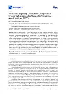
5 Figs. 1-3 show the trajectory plots for fan angle of inclinations of 60, 90 and 1200 respectively for particle inlet velocity of 0.25 m s-1 and air velocities of 3.6 and 7.5 m s-1, and maximum x and y value of 1 m. From the trajectory plots, particles with Vt ≤ 3.0 ms-1 represent light materials
(a)
Air velocity of 3.6 ms-1
(b)
Air velocity of 7.5 ms-1
Fig. 1: Particle trajectory produced from the 2D model at fan inclination of 600 and inlet velocity of 0.25 ms-1 ______________________________________________________________________________ B. Adewumi, A. Ogunlowo and C. Ademosun. “Investigating Particle Trajectory as a Parameter for Selecting the Dimensions of Cross Flow Grain Classifier” Agricultural Engineering International: the CIGR Ejournal. Manuscript FP 06 007 VIII. July, 2006.
6 while particles with Vt ≤ 7 ms-1 represent heavier materials (grains) The heavier materials are expected to have a maximum lateral displacement of 0.9 m while the lighter materials are blown off, far ahead. Also the lighter particles are expected to have a maximum of 0.6m vertical displacement. Hence, a lateral axis greater than 0.8m and a vertical axis greater than 0.6m are adequate for the separation unit.
(a)
Air velocity of 3.6 ms-1
(b)
Air velocity of 7.5 ms-1
Fig. 2: Particle trajectory produced from the 2D model at fan inclination of 900 and inlet velocity of 0.25 ms-1 ______________________________________________________________________________ B. Adewumi, A. Ogunlowo and C. Ademosun. “Investigating Particle Trajectory as a Parameter for Selecting the Dimensions of Cross Flow Grain Classifier” Agricultural Engineering International: the CIGR Ejournal. Manuscript FP 06 007 VIII. July, 2006.
7
(a)
Air velocity of 3.6 ms-1
(b)
Air velocity of 7.5 ms-1
Fig. 3: Particle trajectory produced from the 2D model at fan inclination of 1200 and inlet velocity of 0.25 ms-1 ______________________________________________________________________________ B. Adewumi, A. Ogunlowo and C. Ademosun. “Investigating Particle Trajectory as a Parameter for Selecting the Dimensions of Cross Flow Grain Classifier” Agricultural Engineering International: the CIGR Ejournal. Manuscript FP 06 007 VIII. July, 2006.
8 2.2 Fabrication and Testing of the Cross Flow Classifier A practicable dimension of 0.99 x 1.3 m was selected for the cleaning unit, considering the space requirements for free fall of the materials (Kashayap and Pandya, 1986; Fernando and Hanna, 2005). A thresher-cleaner with cross flow classifier was fabricated at the Department of Agricultural Engineering, Federal of Technology, Akure, Nigeria and described in Adewumi (2005); Adewumi et al. (2005; 2006b). Fig. 4 shows the diagram of the classifier while Fig. 5 shows a sketch of material flow in the cross flow chamber. The classifier was tested with cowpea discharged from the thresher unit at a pod moisture content of 14.0%, grain moisture content of 15.3%, fan angles of inclination of 60, 90 and 1200, and fan speeds of 900 and 1500 rpm. Materials fed into the classifier are a mixture of whole and damaged/ broken grains, and whole and broken pods. The materials were collected in a collector partitioned at 12.5 cm intervals. About 65% of materials loaded into the classifier were pod while 35% was grain. The materials collected in each of the trays were classified into 8 groups, as shown on Table 1. Experiments were conducted in triplicates and the mean value is used for the discussions
Fig. 4: FUTA Thresher - Cleaner
______________________________________________________________________________ B. Adewumi, A. Ogunlowo and C. Ademosun. “Investigating Particle Trajectory as a Parameter for Selecting the Dimensions of Cross Flow Grain Classifier” Agricultural Engineering International: the CIGR Ejournal. Manuscript FP 06 007 VIII. July, 2006.
9
Fig. 5: Sketch of the Experimental Set up and Material Flow in the Classifier
Table 1: Classification of material loaded into the cleaning chamber Material Specification Size range (mm) Cowpea (Whole Seeds)
Big size Medium size Small size
7.00 < x