IRVE-Serve: A Visualization Framework for Spatially-Registered Time Series Data Nicholas F. Polys
[email protected]
1
2
Michael Shapiro
[email protected] 1
2 3
3
Virginia Polytechnic Institute and State University
Department of Pathology, Tufts University School of Medicine
Kwame Nkrumah University for Science and Technology; Kumasi, GH.
ABSTRACT Scientists regularly confront situations where they are trying to understand large quantities of information, that vary over time and space. Analyzing such systems where structure and function are related is still a challenge despite the continued improvement of visualization tools and techniques. Given the spatial basis of many simulations, Information Rich Virtual Environments (IRVEs) can be a successful way of presenting heterogeneous information in an intuitively comprehensible form. In this paper we describe the evolution of a web-based IRVE delivery system for simulation data. Our framework decouples geometry, the underlying data set, and the expressive repertory for information display. This allows us to incorporate domain-specific information while providing for easy retargeting of the information displayed in that domain. As a result of these abstractions, we are able to continually expand and improve our visual mappings and components and finally apply our framework in a completely unrelated domain.
Categories and Subject Descriptors H.5.1 [Information Interfaces and Presentation]: Multimedia Information Systems – Artificial, augmented, and virtual realities,
General Terms Design, Standardization.
Keywords 3D Interaction, Environments.
Karen Duca
[email protected]
time integrated information space for this data, we developed an Information-Rich Virtual Environment (IRVE) [Bowman et al 2003] system geared towards a centralized simulation with distributed access and visualization capabilities. Because scientists are attempting to extend existing knowledge, they do not always know what they are looking for. As a consequence, the necessary ingredients for analysis and discovery may not be known a priori. Visualization tools must be flexible enough to support opportunistic questions and hypotheses with little specialized modification. The origin of this framework we call ‘IRVE-Serve’ begins with a visualization front end for Pathsim, an agent-based pathogen simulation of Epstein-Barr virus infection [Polys et al. 2004]. The most recent incarnation of this framework delivers an IRVE adapted to an entirely different simulation engine - that of the energetic behavior of large space structures. The evolution of this framework illustrates the benefits of abstraction and encapsulation for spatially-registered simulations; we present a flexible tool for composing and delivering IRVEs across simulation domains. In Pathsim, seven biological species (virus, plus T-cells and Bcells in various states) interact in the tonsils, lymph and blood. The tonsils were modeled as a three dimensional anatomical structure, while the blood and lymph were represented as abstract ‘compartments’. The populations of the agent species vary both over time and how they are spatially distributed. By displaying these data in an IRVE, we intend to make these virtual biological processes intelligible to the biomedical researchers who were the primary clients of the simulation. Some requirements were easy to identify:
Visual
Design,
Information-Rich
Virtual
1. INTRODUCTION In this paper, we describe the evolution of a visualization framework driven by the need to structure and represent largequantities of multidimensional data in a comprehensible form. Spatially-registered time series data is a common type of data in simulation where an object or point in space has some set of properties or attributes that change over time. To provide a real-
•
The service must be available over the web to serve working groups in different locations.
•
The system must give the bio-medical researchers sufficient control over the working simulation to be able to launch and monitor the runs which will help them generate and test hypotheses.
•
It must simultaneously insulate them from the mundane details of run management.
•
It must display the results of runs in a multitude of intuitively comprehensible manners.
•
It must give researchers direct access to the underlying information in order to enable further analysis in other formats.
In the first version of Pathsim Visualizer (see [Polys et al. 2004]), we attempted to meet these requirements through user-centered design and usability engineering methods. We learned that neither the developers nor the end users know in advance what they will want to look at or how the will want to look at it. For example, how should the data be normalized? Should the per-tonsil data for a given species (e.g., free virus) be normalized as a fraction of current total free virus? As a fraction of the maximum total free virus? As a fraction of the maximum free virus for that tonsil? This dictated a search for a framework in which these data transformations and representations can be easily changed. Our solution was to decouple the problem into geometry, expressive repertory, the information to be displayed via this repertory, and the underlying data which is being studied. The data being studied is the output of a given run; the geometry includes the three dimensional layout where that simulation took place (e.g. the tonsils and their subdivisions). The information to be displayed includes such choices as the normalizations mentioned above, but can be far more general. For example, one might wish to display the log of the number of infected B-cells, or the ratio between the number of infected Bcells and the number of free virus. The expressive repertory includes such things as the ability to map information to geometry color over space and time, the ability to display numbers or graphs of time series, etc. In the following sections, we describe how the original biomedical visualization system was extended and applied more generally for the transformation and instantiation of spatiallyregistered time series visualizations. We begin by covering the background related to the original system including a brief explanation of the biology, the simulation, and the framework. In Section 3 we detail the implementation of the PathsSim Visualizer from its initial version to its Object-Oriented version. Section 4 demonstrates our application of the framework to an entirely different domain – the energetics of space structures. Section 5 summarized technical problems encountered and Section 6 contains our conclusions and prospects for future work.
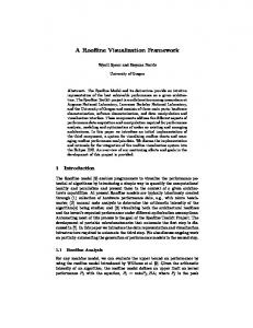
2.2 Pathsim Simulation Pathsim is a large agent-based simulation of the dynamics of Epstein-Barr virus infection and our immune responses to it. Pathsim provides a three-dimensional graph representing Waldeyer’s ring, i.e., the oropharynx - tonsils, the adenoids and their connecting tissue. In addition, two abstract compartments represent the lymph and the circulation. These constitute an arena in which seven different agent types interact. These agent types include free virus, the cells which become infected by the virus, and those cells of the immune system responsible for regulating the resulting infection (more detailed descriptions can be found in [Shapiro et al. submitted; Thorley-Lawson et al. submitted]). As the sizes and locations of these agent populations shift over time, the visualization engine attempts to tell their story. Pathsim is a C++ application that runs under Linux. It consists of an environment engine and a rule set. On launch, Pathsim reads a configuration file specifying the simulation parameters; these include things like the size of the tonsils, initial agent demographics, and the probability values governing agent interaction. Typical simulation environments involve over 160,000 mesh points, 800,000-plus time steps, and seven different agent species whose populations sum to upwards of 7 million agents. The number of time steps is reduced for display purposes. The simulation first generates a hierarchical anatomical mesh according to the dimensions of the virtual patient. This ‘agent transportation network’ through the tonsils and adenoids are described in combinations of hexagonal units (Figure 1). Based on clinical averages, there are defaults for each tonsil’s surface area. Once the tissue is built in memory, it is output as a VRML file where each recorded tissue volume is DEF-ed with a unique ID corresponding to its ID in the simulation and located in 3D space [Web3D Consortium 2007].
2. BACKGROUND 2.1 Biomedical Background Epstein-Barr Virus (EBV) infects greater than 90% of all people and is usually benign, though it is also responsible for acute infectious mononucleosis and can result in some cancers, particularly in transplant patients whose immune systems have been suppressed. The main biological systems of infection are the circulation and the ring of tonsilar tissue at the top of the throat the Waldeyer’s ring. This ring of tissue consists of four tonsils and two adenoids. The Epstein-Barr virus is transmitted in saliva and infects naïve B-cells. These infected B-cells migrate to the follicles of the tonsil (also known as ‘germinal centers’) where they enter a latent state. They can then enter the circulation. When they return from the circulation to the tonsilar ring, they can become lytic and die, producing a burst of fresh virus. The host immune system’s response involves the activation of naïve T-cells to regulate the infected B-cells.
Figure 1: A generated simulation environment from Pathsim (VRML) As the simulation time advances, agents move through the tissue network and interact. The smallest simulation time interval is 6 minutes and time step output may be written at any multiple of this simulation time basis. At each output, the system appends the population values for each agent to the output files for each tonsil and each basic tissue unit.
Figure 2: Service Architecture for Pathsim Web Interface Pathsim uses a naming convention of unique RunIDs for each execution. These RunIDs are also the names of folders inside the ‘Results Directory’ (e.g. ../Results/RunID/) where parameters and output for each execution are organized and stored. Parameter files are tab-delimited text files that can be edited by hand or through a web-based form; output files are tab-delimited text.
2.3 Pathsim Simulation Server This project involved the cooperation of clinicians, bio-medical researchers, software developers and mathematicians. These people were located at multiple sites. Accordingly, Pathsim was configured to run from a central server. Through a CGI + HTML front-end, remote collaborators can setup, initiate, cancel, and analyze a simulation on this dedicated computing resource over the web. Figure 2 shows the overall service architecture for the system. For example, researchers need to: • • • • • •
Setup and invoke a new run Process output for visualization / analysis Manage results (delete, zip, download) View results Manage server threads View documentation
The web interface insulated our collaborators from the details of run management. In general, significant processing of visualization mappings such as re-tabulation, normalization, or scaling of the time points is run on the server. From the client perspective, processed simulation data is structured and available through the website directory structure. An HTML frameset allows the user to navigate the /Results directory to examine existing runs and parameter files. To launch a run, users login and open the parameters page. Through web forms (with default values), users can enter and modify a host of simulation parameters covering:
• Simulation and output: time span and time interval • Agent properties • Agent interaction parameters • Initialization parameters After the user has submitted the parameters via the web form, they are printed out again for confirmation. Once the parameters are confirmed by the user, the simulation is initiated. For each run, a folder is created to store all information related to that run including the parameters file used, the simulation geometry generated for the simulation, and the time series output files. The time series output files are updated after every time step so during runtime, the latest data point is visible outside the simulation itself. File naming conventions are crucial to maintain organization of multiple runs as well as the environment and agent data for each unit scale. For each run, the global and macro scale data is written into the /Results/thisRunID folder. For the smaller scales of each simulated tissue region, named folders are added beneath /Results/thisRunID.
3. PATHSIM VISUALIZER When a user wants to examine simulation output, there are a number of options. From the web interface (or a local command line) users can invoke scripts to process the data for common and research tools such as Excel, TimeSearcher [Hochheiser & Shneiderman 2004], and VRML IRVE output. The Excel and TimeSearcher scripts simply transform the output data into a tabular format that each application can read. These tools are useful for a number of analytic and visualization tasks. However they do not represent the spatial relationships of the anatomy well. The VRML IRVE allows us to represent much more information in a single integrated information space. The first version of the processing scripts required numerous scene fragments to be managed and merged and soon became a maintenance nightmare. The second Object-Oriented version
composes scene files using lexical substitution in otherwise legal VRML files.
3.1 Visualizer Version 1 PathSim Visualizer version 1 [Polys et al. 2004] was an early prototype of the application server concept and consisted of a set of Perl scripts that would read the simulation data and process it in such a way as to write various fields of VRML PROTO instances. This publication process could be characterized as a ‘Composition Paradigm’ where data and scene resources are collected and merged into complete files [Polys 2005].
3.3 Visualization Runtime Components Through the user-centered design process we established a number of requirements: 1.
Qualitative and quantitative apprehension of population dynamics across anatomical space and shapes
2.
Qualitative and quantitative apprehension of population dynamics across scales
3.
Qualitative and quantitative apprehension of population dynamics across time
Once the VRML files exist in the /Results directory of the web server, they can be viewed or downloaded. In addition, Perl processing routines were added to generate Excel spreadsheets and TimeSearcher files for each run. The processing scripts can run on any currently available output, even if the run in question has not completed. This feature is important since wall-time runs of a week or more are common. Since the original system, we have made significant improvements to both the visualization processing scripts and the target VRML nodes.
We built a set of VRML PROTO objects to realize these requirements. In addition to those custom nodes described for Pathsim Visualizer 1, such as Semantic Objects and MF String and Float Sequencers, we require our information visualizations to also render the time series as a line graph plot. Also, at our smallest scale of tissue sections, the amount of data is prohibitive to deliver at once; we need a way to dynamically load data into the scenegraph. We describe our techniques, which are realized in VRML, in the following sections.
The first version of the processing scripts required numerous scene fragments to be managed and merged and soon became very difficult to extend and maintain. In addition, we found that some of the choices we had made concerning normalization of data were not those that the biomedical researchers wanted to see.
3.3.1 Information Visualizations
3.2 Visualizer Version 2 As the simulation and the research questions matured, it became less and less feasible to update the giant Perl scripts and integrate new visualization mappings and widgets. Therefore, we undertook a redesign that would be more flexible and maintainable by encapsulating specific visualization processing tasks. The result is a set of Object-Oriented Perl modules that enable the transformation of simulation data into results documents including a VRML Information-Rich Virtual Environment (IRVE).
In spatially-registered time series data, time-varying attributes are registered to points or objects in space. For each spatial item, we wanted to provide views of the agent population that could provide multiple insights across time, space, and scale. We built a custom node called ‘PopView’ that displays population time series data in three ways, each shown in turn by a mouse click selection.
The need to retarget our normalization suggested that further retargeting was likely and that it was likely to be unpredictable. We did not wish to change the simulation, nor did we want to engage in extensive recoding of our VRML code base. This meant that we needed a layer between the data and the expressive repertoire that would allow for easy retargeting. We decided that the seven colors (which formerly represented the seven species) would now represent seven re-targetable data mappings. Thus, yellow would no longer necessarily represent normalized viral population, but could be used to represent any data series supplying a value for a simulation object at each time step. We chose to maintain the categorical meaning of the color across data representations. For example, the property designated as yellow in the HUD and color maps was the same property rendered in yellow in all other views. The data mappings needed to be decoupled from the scene graph. When developers needed to create a new data mapping this should not require them to change the VRML code base. Rather, they should check the new mapping into a function library. Associating any particular data mapping to a color would be carried out by a function mapping which the user could chose when assembling a Pathsim run into a scene graph.
Figure 3: Three visual states of a Pathsim Population View The first PopView view is as a bar graph to represent seven normalized values for an object at this time step. The second view is as Text- field-value pairs of agent species in this object at this time step. The third view is as a line graph of seven attributes for
the object over the entire time course of the simulation. Figure 3 shows agent populations from a Pathsim run; the bar graph values shown are local populations normalized to global populations per species, the time plot is local population. The current time step is highlighted with a cursor. Through Plane and Cylinder Sensor widgets on the line graph, it can be rotated (around the X and Y axes), scaled (across X, Y, and Z), or translated (in X and Y). There are a few notable things about our implementation of the PopView annotation. First, PopViews have three fields to be populated with simulation data: one for absolute numbers per agent per time step written as an MFString, one MFFloat for regional maxima per agent over the entire time series, and one MFFloat for normalized values per agent per time step. The numeric view and the line graph drawing routine use the strings in the absolute field. This is an important point because client-side computations in VRML JavaScript (such as the line graph drawing routine) cannot handle Long Integers such as those produced with Pathsim populations. Therefore, for drawing the agent time step value line graph, we truncate population values at the thousandth place. The bar graph uses the values in the normalized field. A PopView annotation needs only an SFFloat timeFraction eventIn to render the data for that particular time step. The second aspect is our use and reuse of another visualization abstractions implemented as a custom PROTOs: the TextPanel {} and the DataExtrusion{}. The TextPanel is an abstraction for labels containing a title and a set of field-values pairs. Because the strings are dynamic and the system cannot know beforehand how many digital agents there will be in the simulation, the size of the background panel of the TextPanel is dynamically estimated based on the number of characters, style, fontStyle, and justification of its strings. The DataExtrusion{} draws a colored line where its MFVec3f data points [ ] define an Extrusion { spine [ ]}. Because there may be many data points in a given line and many lines in a scene, we use a minimal triangular crossSection and only expose diffuse and emissive Color.
3.3.2 Multi-scale Management Due to the large sizes of Pathsim datasets, it is not practical to deliver them to the client at once in entirety. We needed a way to provide “overview first, then zoom and filter for details on demand” [Shneiderman 1996]. This necessitated dividing up the IRVE visualization along scales that were manageable for real time frame rates and dynamic content loading. Figure 4 shows the implemented levels of scale for the Pathsim IRVE. When users first load the Pathsim IRVE, they are delivered the global population time series, the HUD and time controller, and static anatomy such as the body and skull. As they zoom into the oropharynx, macro-scale data (for the tonsils, blood, and lymph) is loaded (Figure 5, Colour Plate). As they zoom further into a specific tonsil, the micro scale visualization is loaded (Figure 6, Colour Plate). When they select individual tissue sections, numeric and graphical annotations are delivered (Figure 7, Colour Plate). As users explore the simulation, they can travel between two scales: the micro and the macro. For each nested scale or object, we wanted to provide awareness of the global or regional dynamics. As they drill down, appropriate visualizations for the scales above them are added to the HUD.
At the top level of the scene graph along with the HUD and time controller is a section of scripts including the SceneManager Script{}. The SceneManager is responsible for knowing what agent map is loaded, what anatomical scale is loaded, and managing ProximitySensors activity. In addition the SceneManager is responsible for adding and removing ROUTEs between the time controller and the current agent/anatomy world. Dynamic scene loading was accomplished through two techniques: loading files that had been written on the server and loading content composed by the server by request on-the fly.
Figure 4: Dynamic content loading of multi-scale information in Pathsim Visualizer
3.3.2.1 VRML File Loading This method of scene graph management involves generating files on the server that are later seamlessly instanced into the main scene as the user zooms into tonsils at the macro and micro scales. In order to keep animation time of scale synchronized to the time controller on the HUD, we wrapped each scale of results inside a PROTO. When the user zooms into a particular region – the Waldeyer’s Ring or a tonsil for example- the current branch of the ‘world’ scene graph is replaced by a PROTO instance of the smaller scale; a timeFraction ROUTE is added to connect it’s animations to the DVD time controller in the HUD. Currently, all interpolators and sequencers in PathSim share the same timebasis. To reduce redundancy across many instances, we ‘baked-in’ the key [ ] time basis into each PROTO definition. The values for the animation key [ ]s are written into each run’s PROTO files by the server system (below).
3.3.2.2 Micro-scale Details on Demand At the micro-scale, the anatomical mesh representing tonsillar tissue is aggregated into hexagonal units. We defined a VRML PROTO for these units with fields for: position, name, serverID, baseColor, keyValue[ ], and maxValue. The SFFloat maxval field is used to locate a hexagonal cap above the hex unit that represents the maximum value achieved for that agent in that section over the course of the entire simulation. The keyValue [ ] is an MFFloat of an agent’s time series in that unit. A hexunit needs only an SFFloat timeFraction eventIn to render the color data for a timestep. We used 7 color schemes, mapping to different combinations of scalar RGB color values. The color scalars did not provide
satisfactory sensitivity over small gradients, so we multiplied the scalar population value of each hexunit by 10 and mapped that to each tissue unit’s height. While this was found to be important for the user to distinguish relative concentrations between tissue sections, it broke the realism of the tonsil anatomy. The second method of dynamic delivery is used at the smallest scale represented in PathSim output: the micro-scale unit tissue section. At this level, users are initially shown the color heat map and height map for a given agent population. This initial view provides a qualitative understanding of the infection dynamics across the tonsil tissue. For a quantitative view at the individual section level, users must select a tissue section just like at the larger scales. However in this case, the data that makes up a numeric/graph annotation is not written on the server, it is generated and delivered on the fly. When selected, the tissue calls Browser.createVrmlFromURL() with a string that points to a CGI script; e.g. http://./Results/gateway/section_query.pl?ServerID+SectionID .
Figure 8: The Object-Oriented System for Pathsim Visualizer
The ServerID parameter includes both the RunID plus an identifier for which tonsil region the section is in; the SectionID is a field of the section as well as the DEF name given to the instance in the scenegraph.
Once the FunctionMap.pm, and DataObject.pm are built and the IRVE.pm is instantiated, the process_master.pl script runs through its list of .wrl scene skeletons calling the SceneTemplateProcessor.pm’s process() method on each. The process_master.pl script iteratively calls this method for each scene skeleton file and so simply passes pointers to the other processing objects.
The section_query.pl script receives the http request and builds a DataObject from the appropriate results files using the serverID and sectionID parameters it is given. After processing the data by way of the IRVE.pm object, VRML code is returned under the model/vrml content type. The VRML code includes an EXTERNPROTO definition and instance of the PopView object (Section 3.3.1), which is then added to the scene. Section_query.pl uses all modules except the SceneTemplateProcessor.pm.
3.4 Server Processing Components To process simulation data for visual display, the web form invokes the processs_master.pl script with a parameter specifying which simulation run to process. This is the main script which marshals all the data and processing resources on the server machine and collects them into the /Results/thisRunID folder. First the script copies all configuration and visualization file resources into the results folder. These resources include a set of VRML files such as Inlines, scene templates (or ‘skeletons’) that will be fleshed out with data, and EXTERNPROTO code that will be modified. The script then invokes the various Perl Modules making up the visual processing system (Figure 3): •
The SceneTemplateProcessor.pm object inserts data into template files via keywords,
•
The FunctionMap.pm object uses a text file to associate keywords to functions and parameters,
•
The IRVE.pm object provides the code to implement mapping functions such as population value to color, log ot linear scaling etc.,
•
The DataObject.pm object reads in the simulation output file and provides methods to get time series data for any spatial item, agent population, maxima, minima, etc.
3.4.1 Scene Templates To process simulation data for visual display, the web form invokes the processs_master.pl script with a parameter specifying which simulation run to process. This is the main script, which marshals all the data and processing resources on the server machine and collects them into a single folder. These resources include a set of VRML files such as Inlines, scene templates (or ‘skeletons’) that will be fleshed out with data, and EXTERNPROTO fields that will be modified. The SceneTemplateProcessor.pm module is a generalpurpose file processing script that runs through a file searching for lines that begin with the #META_INCLUDE keyword. Following this keyword, the tab-delimited line contains a function name that specifies what data is to be inserted into the file at that location. The SceneTemplateProcessor knows nothing of Pathsim or VRML per se. Keywords in a scene skeleton only signal to the system that some information is to be inserted in that (lexical) location and the file saved. The scene templates in our case are syntactically valid VRML files. They include #META_INCLUDE statements which will be processed to insert VRML fields populated with simulation data as keyValue [ ] arrays for example. These #META_INCLUDEs simply mark the location at which to insert some code. For example, where a TimeSensor’s cycleInterval would be defined for the run, a scene skeleton may contain the following line: #META_INCLUDE TIME_INTERVAL The keywords following a #META_INCLUDE may signify any kind of VRML field information to be inserted such as strings, floats, integers, or arrays. It is important to realize that #META_INCLUDE keywords have no meaning until they are resolved according to some visualization function mapping. We describe the resolution process in subsequent sections.
Scene templates give the high-level architecture for a scene. The job of marshalling the scene templates, resolving their #META_INCLUDEs and assembling them into a populated scene graph is carried out by process_master.pl. The resolution of the data to be inserted into the templates is best described from the bottom up.
3.4.2 Encapsulating the Data Pathsim formats its output as a collection of tab-delimited files. The first step in providing flexible access to this data is to encapsulate it as an object with methods that other objects can use to access it. This is implemented in a Perl module, DataObject.pm. When the DataObject is created, it reads in the Pathsim run data and builds a massive array of the spatiallyregistered time series data.. It provides multiple low level views of this data. For example, it has methods for returning: •
The parameters which generated this run
•
The time series for all populations in one region
•
The time series for a specific agent in one region
•
Global maxima for each agent
•
Regional maxima for each agent
•
Time charger routes
The DataObject is expected to evolve in minor ways, if at all. It expects to find its input data in a known format. It could evolve to accommodate population means or some other values, but would not be expected to provide any sophisticated analysis.
3.4.3 Processing the Data This is the job of the function library. These functions live in a Perl module, IRVE.pm. The functions in this module consume the data provided by the DataObject. When they are invoked in the course of processing a scene template, they may be provided with additional parameters. They perform mathematical transformation of their data, and return the results as strings. These strings are the VRML field values to be inserted into the scene template and saved.
•
TIME_KEY TIME_KEY – This associates the time key function provided by IRVE.pm with the TIME_KEY #META_INCLUDE keyword.
•
ADENOID_ABS ABS R1 – Here ADENOID is a geometrical region of the visualization while R1 is the corresponding region for Pathsim’s output data. This associates the IRVE.pm absolute value function applied to the R1 data with the #META_INCLUDE keyword ADENOID_ABS.
4. MIGRATING TO A NEW DOMAIN One of us recently joined a project at Virginia Tech that is investigating mathematical models of space structure energetics by way of simulation. Since the dataset was also a spatiallyregistered time series, we considered how our IRVE-Serve system could be applied to the problem. The IRVE visualization service we developed for Pathsim had evolved into a flexible tool to process and deliver spatially-registered time series data. Through a number of modifications and extensions, which we describe in this section, we were able meet the new researcher’s requirements for visualizing spatial, abstract, and temporal information.
4.1 Requirements The first crucial difference between Pathsim and the energetics simulation is the spatial domain in which the simulation operates. Instead of using shapes as the basic representation (e.g., the regions and sections of Pathsim), the simulation evaluates energies at each mesh point of a shape. This required changes to our existing framework so that it could address these points and connect animation data to them. Figure 9 shows the addition of a new object to the system that is responsible for handling the geometry of the simulation mesh. Second, the time series output was formatted differently. In order to use the new output file for our internal data structures, we had to adapt our parsing objects to handle the new data. Lastly, instead of having multiple integer time series (agent population counts) associated to each location, we had a single real valued time series (watts/meter2) at each location.
Typical functions in IRVE.pm process the time series’ •
Total population for a given species in a given region
•
Total population for a given species in a given region as a fraction of total population for that series
•
Log of total population for a given species in a given region
•
Other VRML resources such as labels, wrappers for PROTOs and time charger routes.
Finally, the link between the #META_INCLUDEs of the scene templates and the functions named in IRVE.pm is encapsulated in a Perl module FunctionMap.pm which relies on the mappings contained in a text file called fxn_map.txt. This file contains tab-delimited data. The first field is the #META_INCLUDE keyword from the scene template that needs to be resolved. The second field is the IRVE.pm function to resolve it to. Additional fields provide parameters to this function such as agent, region, label, etc. Typical statements are: •
COLOR_1_LABEL MESSAGE EBV – This associates the label EBV with the heat map color yellow.
Figure 9: The Object-Oriented System for producing IRVEs with MeshObjects
4.2 Encapsulating the New Geometry The first change for this new application required that we implement a way to represent the simulation domain, in this case, the mesh. In the Pathsim visualizer, we relied on VRML produced by the simulation for our geometry. Here, we chose to encapsulate the geometry in a Perl object, MeshObject.pm. Our mesh is a fixed topology: a tubular, structural support of a satellite truss. The researchers’ MatLab code outputs a coordinate.dat file, which describes the number of length segments and the number of sides around the circumference of the tube. Similar to Pathsim, many simulations may be run and varying mesh resolutions used. In this case, resolutions are described by the number of sampled points in the (2D) X and Y dimensions of the tube itself. Accordingly, the MeshObject must calculate its vertices from the coordinates.dat file and compute the location of the tube’s mesh points. The MeshObject exposes these to the rest of the visualization processing system through the getPointArray() method. The points can be indexed in a number of ways but we were most successful using quadrilateral lines or faces. Currently we tessellate the tube using the method getQuadFaceIndices() (Figure 10).
Figure 10: A variety of meshes from the space structure simulation engine
4.3 Encapsulating the New Data In addition, we had to update our DataObject to parse the new simulation output format. This required changing the build() method to parse a new ordering of data points into its internal data structure. Because these time series may contain negative values, a new method was also added to retrieve a data item’s minimal value (over the course of the simulation).
4.4 Color Interpolation The spatial objects in this space structure simulation are mesh points within one Shape{}. In order to drive the Color{} node’s per-vertex coloring from time series data, we built an MFColorInterpolator{} using Braden McDaniel’s ColorArrayInterpolator{} [McDaniel 1999]. This required a corresponding new function in IRVE.pm to map both positive and negative values to the RGB color values in an MFColor array. Figures 11 and 12 (Color plate) shows the result of the processing.
functionality by selection for PopView annotations to display the three views of the vertex time series. However, the initial results were not encouraging. Although our current application only renders one attribute for the time series in a PopView, when we included PopView data for all mesh points we quickly ran into memory limitations that significantly reduced frame rate. The solution we pursued is similar to that used at the micro scale in Pathsim: we only deliver PopView data to the scene when it is requested by the user. We implemented this using Browser.createVrmlFromURL() method where the PopView data for each mesh point is written into individual files in the /Results/RunID/perpoint/ folder. This approach does save processing time and the requirement of a live network, but costs in terms of hard disk storage.
5. TECHINCAL NOTES In the process of implementing IRVE-Serve, we discovered a number of pragmatic limitations that are worth mentioning. First, when we tried to use PHP as the CGI processing mechanism, we ran out of memory when processing large data arrays. In contrast, Perl is able to handle operations on the majority (but not all) of our large arrays. Our current working solution is to warn users not to run a nine month-long infection scenario while recording simulation output every twenty (simulation time) minutes. Many of our scene graph techniques rely on the use of SF or MF Nodes on PROTO interface fields. Unfortunately, this is not supported in some browsers and limits the adoption of our system at least in the short term. Regarding node usage in PROTO interfaces, we expect them to be copied by value into the PROTO sub-graph instance. We hope that through clarification of the specification, more engines will support this technique. When using the Browser interface to dynamically deliver data (as we did with section_query.pl), we were introduced to another memory ceiling – that of JavaScript’s createVrmlFromString(). Because storing strings is expensive, some of our larger Pathsim data sets overran memory when delivering arrays of all data points via a PopView. Therefore depending on the number of time steps in a run, we down-sample the data used for the DataExtrusion{} line graph. Because there are more data points in a longer time series, this has little visual effect. We ran into a limitation when using the VRML colour model for scientific visualization: RGB colour does not provide perceptually linear palettes (as does HSV or luminance) [Ware 2000]. We consider this problematic when trying to visually represent scalar values in a pre-attentive form. One solution within the VRML idiom is to implement an HSV to RGB. This could be done server-side in our Perl function library or client-side in JavaScript or Java.
4.5 Information Visualizations
6. CONCLUSIONS AND FUTURE WORK
Our initial data sets from this simulation have time series data for anywhere from 249 to1896 mesh points. Beyond providing some mapping functions to per vertex color scales, we wanted to include the other representations of the data, such as the PopView object. We modified the PopView visualization so the graphs could display positive and negative X and Y values. We also locate a TouchSensor {} at each vertex point instanced with a small transparent cube. This provides the details on demand
This paper has documented the common web publication framework behind the implementation of two visual simulation applications. Both application domains, population dynamics and the energetics of space structures, deal with spatially-registered time series data. The challenge common to both is delivering large quantities of information in a way that is easily comprehensible and interactive for overview plus details on demand. Our architecture makes no assumptions about what data or attributes
may be interesting to the end user. The mapping functions and function library provide the means to customize and extend the visual representation for the client.
library for the DVDController {} PROTO (adapted) and to Braden McDaniel for the ColorArrayInterpolator {} PROTO.
We have described the evolution of the IRVE-Serve visualization framework as it became more general-purpose and finally was able to be applied to a new simulation domain. We discovered that without good abstractions and encapsulation of functionality, the code became difficult to maintain and extend. Furthermore, when one of our choices for normalizing data proved not to be what our biomedical researchers wanted, we decided to abandon the idea that we could predict their needs. To accommodate future choices, we decoupled geometry, expressive repertoire, data mapping and underlying data. A simple lexical device – the introduction of #META_INCLUDE statements into VRML fragments turns these into scene templates whose expressive repertoire can be coupled to different data mappings by choices made in a function map.
8. REFERENCES
This architecture allows developers to provide researchers with additional visual/analytic tools by checking new functions into a function library. They need not revise any other part of the existing code base. This flexibility is important when working with a scientific community where attention inevitably focuses on new factors as a result of new insights and the questions they generate. There are many opportunities for future work. Primary among these will to be to migrate the system to X3D where we can take advantage of a number of exciting new visualization features including RGBA color, Layers, Particle Systems & Shaders. However, it is not just the improved node-set that attracts us to X3D. The Scene Access Interface (SAI) programming interface provides much more extensive services for X3D runtime and scene management. For example, the pre-eminently useful method getNode() by DEF name is not supported in VRML’s javascript binding.
BOWMAN, D., NORTH, C., CHEN, J., POLYS, N., PYLA, P., and YILMAZ, U. Information-Rich Virtual Environments: Theory, Tools, and Research Agenda. In: Proceedings of ACM Virtual Reality Software and Technology (Osaka, Japan). ACM Press, 2003. HOCHHEISER, H., SHNEIDERMAN, B. Dynamic Query Tools for Time Series Data Sets, Timebox Widgets for Interactive Exploration. Information Visualization, Palgrave-Macmillan 3, 1-18. 2004. MCDANIEL, B. ColorArrayInterpolator. http://www.endoframe.com/vrml/protos/index.html 2007)
(accessed
POLYS, N., BOWMAN, D., NORTH, C., LAUBENBACHER, R., DUCA, K. PathSim Visualizer: An Information-Rich Virtual Environment for Systems Biology. In: Web3D Symposium (Monterey, CA). ACM Press, 2004. POLYS, N. F. Publishing Paradigms with X3D. In: Information Visualization with SVG and X3D, ed. Vladimir. Geromenko & Chanomei Chen, Springer-Verlag, 2005. POLYS, N. F. Display Techniques in Information-Rich Virtual Environments, Ph.D. Thesis. Virginia Polytechnic Institute and State University, Blacksburg, VA. http://scholar.lib.vt.edu/theses/available/etd-06152006-024611/ (accessed 2007). SHAPIRO, M., DUCA, K., LEE, K., DELGADO-ECKERT, E., JARRAH, A.S., LAUBENBACHER, R., POLYS, N.F., HADINOTO, V. THORLEY-LAWSON, D. A. Virtual Look at Epstein-Barr Virus Infection: Simulation Mechanism. Submitted to PLOS Pathogens 2006.
In addition we also intend to migrate our runtime Scripts to Java for better handling of essential data-types such as Arrays, Longs, and Doubles. The architecture of the IRVE-Serve visualization system provides our initial answer to the requirements of publishing spatially registered time series data.
SHNEIDERMAN, B. The eyes have it: A task by data type taxonomy for information visualizations. In: Proceedings of IEEE Visual Languages (Boulder, CO). 1996.
Finally, with such a flexible framework in place, we can extend Human Computer Interaction research for IRVEs. Polys [2006] has investigated the roles of perceptual cues in IRVE layouts. Continued progress involves more formal study of the use of IRVEs as applied problem-solving environments.
THORLEY-LAWSON, D. A., HADINOTO, V., LUZURIAGA, V., JARRAH, A.S., LAUBENBACHER, R., LEE, K., POLYS, N.F., DELGADO-ECKERT, E., SHAPIRO, M., DUCA, K. A Virtual Look at Epstein-Barr Virus Infection: Biological Interpretations. Submitted to PLOS Pathogens 2006.
7. ACKNOWLEDGMENTS
WARE, C. Information Visualization: Perception for Design New York, Morgan Kauffman.2000.
The PathSim work was supported by a Public Health Service grant (RO1 AI062989) to David Thorley-Lawson. Thanks to Doug Bowman and Chris North for supporting IRVE research; Eugene Cliff and Terry Herdman for information and data sets for the space structure simulation. Thanks to the NPS SAVAGE
WEB3D, CONSORTIUM. X3D Specification, VRML Specification. ISO http://www.web3d.org (accessed 2007).