Java Framework for Distributed Real-Time Embedded Systems Elias Teodoro Silva Jr1,2; Edison Pignaton Freitas1; Flávio Rech Wagner1; Fabiano Costa Carvalho1; Carlos Eduardo Pereira1,3 1 Instituto de Informática, Federal University of Rio Grande do Sul, Brazil {etsilvajr, epfreitas, flavio, fccarvalho}@inf.ufrgs.br 2 on leave from Federal Center of Technological Education of Ceará, Brazil 3 Electrical Engineering Department, Federal University of Rio Grande do Sul, Brazil
[email protected] Abstract This paper presents the evaluation of a multithread distributed real-time object-oriented platform. A communication API was developed to increase functionalities of an API that implements the RealTime Specification for Java standard, extending it to cover embedded distributed applications. Real-time restrictions of the communication are ensured by a time-out mechanism. The API can be adapted to be used with different underlying network and physical mediums. The development focused on restrictive embedded platforms with low performance and small memory. An evaluation in terms of the fulfillment of timing constraints, and memory footprint is presented for a CAN-bus network. The results also demonstrate the timely correctness provided by the communication API running over an RTSJ implementation.
1. Introduction Embedded real-time systems are becoming more complex, requiring distributing facilities in order to put processing units where their services are demanded, thus turning control and command activities more efficient. A lot of examples can be quoted, like automobile control (steer-by-wire), airplane control (fly-by-wire), or sensor networks. In this context, it is not enough to have physically-distributed processing units, but they also need to be able to communicate, to solve the problem in a cooperative way. Over the last years, Java gained popularity as a suitable programming language for embedded and real-time systems development. The definition of the Real-Time Specification for Java (RTSJ) standard [1] is the most prominent example of such popularization in the real-time domain. The RTSJ defines an Application Programming Interface (API) for the Java language that allows the creation, verification,
analysis, execution, and management of real-time threads, whose correction also depends on the fulfillment of timing requirements. However, it does not take in account Java distributed programming issues. Consequently, a Distributed RTSJ (DRTSJ) Expert Group has been set up under the Java Community Process [2]. An initial framework by the expert group for integrating the RTSJ with RMI describes three levels of integration [3]. At Level (0), real-time Java virtual machines (RT-JVMs) communicate via standard RMI. No guarantee of timely delivery of a remote request can be assumed, and the programmer must explicitly pass scheduling and release parameters with each call. This requires no extension of either RMI or the RTSJ. At integration Level (1), the notion of a real-time remote object is introduced and supported by a real-time RMI that provides timely invocation guarantees. Level (2) of integration augments Level (1) with distributed thread model semantics. Borg and Wellings [4] explore facilities that must be provided by a real-time RMI (RT-RMI), focusing on integration level (1), as defined in [3]. Their work differs from that presented in this paper in that they assume a real-time network and consider the real-time aspects at a higher level, focusing on the remote invocation of threads. Our work, in turn, considers facilities at a lower abstraction level, providing a unicast/broadcast mechanism to exchange messages meeting time restrictions. Moreover, our development is focused on embedded platforms with restricted performance and tight memory resources, such as those used in control applications, while RTRMI does not consider these restrictions. The goal of this paper is to present a framework for real-time communication using Java, aimed at applications that run over an embedded platform with restricted resources. This platform implements RTSJ and natively executes Java bytecodes. A case study in
Proceedings of the Ninth IEEE International Symposium on Object and Component-Oriented Real-Time Distributed Computing 0-7695-2561-X/06 $20.00 © 2006
IEEE
vehicle automation was chosen, since it requires distribution to fulfill functional requirements. This work does not intend to provide a full solution to automobile industry. Its main interest is to explore the resources provided by a real-time Java platform, analyzing latencies introduced by the communication API, the fulfillment of timing constraints, and memory usage, which are important requirements in many embedded applications. This work is part of a larger research effort that intends to provide a flexible and reusable network support to higher abstraction layers (middleware). The remaining of this paper is organized as follows. Section 2 gives a brief overview of the hardware and software aspects of the development platform, which is based on the FemtoJava processor, a customizable RTJava processor. Section 3 presents the proposed communication architecture. Section 4 presents a case study in the automotive automation domain. Section 5 shows experimental results from simulations providing latencies and memory measures. Finally, Section 6 draws the main conclusions of the paper and discusses future work.
2. Development platform 2.1. JAVA-RT configurable processor The development platform used in this work is the FemtoJava processor [5], a stack-based microcontroller that natively executes Java bytecodes, whose major characteristics are a reduced and configurable instruction set, Harvard architecture, and small size. It implements an execution engine for Java in hardware, through a stack machine that is compatible with the specification of the Java Virtual Machine (JVM). A compiler that follows the JVM specification is used and allows the synthesis of an ASIP (applicationspecific integrated processor) version of FemtoJava. For real-time applications, a multi-cycle version of FemtoJava is used. It implements a subset of the JVM bytecodes, with 68 instructions. The supported instructions are basic integer arithmetic and bitwise operations, conditional and unconditional jumps, load/store instructions, stack operations, and two extra bytecodes for arbitrary load/store. In this processor, all instructions are executed in 3, 4, 7, or 14 cycles, because the microcontroller is cacheless and several instructions are memory bound. In order to support multithread applications, the instruction set of FemtoJava was expanded, with the inclusion of bytecodes putfield, getfield, invokevirtual, invokespecial, and instanceof [6]. Additionally,
two pseudo-bytecodes, save-ctx and restore-ctx, were created to provide context switching [7]. Enhancements in FemtoJava performance are obtained with pipelined and VLIW versions of the processor [8] or even using resources implemented in hardware [9].
2.2. Design and simulation tools The Sashimi environment [5] is used to generate customized code for the application. The code includes the VHDL description of the processor core and ROM (programs) and RAM (variables) memories and can be used to simulate and synthesize the application. Sashimi is an example of JVM optimization for embedded systems. It provides a powerful and easy-touse development environment for embedded systems that has been successfully applied to different case studies. The Sashimi environment has been extended to incorporate an API [10] that supports the objectoriented specification of concurrent tasks and allows the specification of timing constraints, implementing the RTSJ standard. These facilities increase the code abstraction level and optimize the development of realtime embedded systems. The intent is to minimize architecture-dependent characteristics within the scheduling algorithms, thus making the framework as general as possible. The RTSJ-API uses the concept of schedulable objects, which are instances of classes that implement the Schedulable interface, for instance the RealtimeThread. It also uses a set of classes to store parameters that represent a particular resource demand from one or more schedulable objects. The ReleaseParameters class (superclass of AperiodicParameters and PeriodicParameters), for example, includes several useful parameters for the specification of realtime requirements. Moreover, the API supports the expression of the following elements: absolute and relative time values, timers, periodic and aperiodic tasks, and scheduling policies. The term ‘task’ derives from the scheduling literature, representing a schedulable element within the system context. It is also a synonym for schedulable object.
3. Communication API In order to provide communication facilities, an API (APICOM) was developed for the real-time FemtoJava processor, providing an interface to the application layer.
Proceedings of the Ninth IEEE International Symposium on Object and Component-Oriented Real-Time Distributed Computing 0-7695-2561-X/06 $20.00 © 2006
IEEE
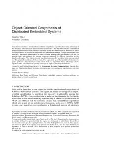
The communication system was proposed to provide message exchange among applications running in different FemtoJava processors. The API allows applications to establish a communication channel through the network, which can be used to send and receive messages. The service allows the assignment of different priorities to messages and can run in a multithread environment. From the application pointof-view, the system is able to open and close connections, in a client-server mode, or even to run in a publish-subscribe mode. Figure 1 shows the overall platform architecture, which includes the APICOM. The APICOM works together with the RTSJ-API, using the FemtoJava features to provide communication via a network interface. 1
n
APPLICATION
APICOM
APPLICATION
RTSJ
Network FemtoJava Interface Architecture
APICOM
...
RTSJ
Network FemtoJava Interface Architecture
Communication Bus
FemtoJava (FemtoJava processor with RTSJ-API). However, communication features are also important, since threads can be distributed in several processors. Some distributed applications have a large number of control packets exchanged during their execution. Some packets are addressed to a specific host. This feature supposes that packets contain their destination address. This way, the API should provide a connection-oriented communication. There are also packets addressed to all hosts in the network, and so the API should support broadcast too.
3.2. The APICOM model The class diagram of the APICOM is presented in Figure 2. The class Transport represents the front-end that provides the interface to final applications. This class is also responsible for breaking messages into packets. The class Message represents the information that comes from the application (or will be received from a remote connection). TransportConnection is the class that makes possible the individualization of each connection between two hosts. It keeps the host logic addresses and the ports of the connections. The class Network works like a filter of packets. It selects packets that are addressed to the local host and redirects them to the class Transport. The received packets that are not addressed to the local host are discarded.
Figure 1: General Platform Architecture +Messages
+outPack 1
3.1. Requirements for the APICOM There are two main viewpoints that can be considered when requirements for the APICOM are analyzed: 1 – Resource availability Distributed embedded real-time systems have a strong demand for performance, in order to meet the timing requirements. In the other hand, they do not dispose of powerful processing resources, since they must have limited area and small memory and meet power consumption restrictions. Another important factor is the underlying network. The developer would like to send messages, abstracting the network frame format and physical layer details. 2 – Application constraints Embedded applications are growing in complexity, becoming multithread and needing real-time support. Multithreading and real-time are provided by the RT-
1
Pack
*
TransportConnection
Transport 1..* +inPacks
1
1
* +Connections
Network
CanPack
1
FielBusPack
1 DataLink
DataLinkCan
DataLinkFielBus
Figure 2: Class diagram of the APICOM The class DataLink is responsible for the final packet transmission. To perform this, it breaks the message into frames that are specific for each network type that is used in the physical layer. In order to reuse the APICOM over different network technologies, this class was modeled as an abstract class. Therefore, by extending this class it is possible to implement a dedicated class for a certain type of network. Classes
Proceedings of the Ninth IEEE International Symposium on Object and Component-Oriented Real-Time Distributed Computing 0-7695-2561-X/06 $20.00 © 2006
IEEE
Message
DataLinkCan and DataLinkFieldBus provide the specific implementation of CAN (Control Area Network) and Field Bus network, respectively. To define Pack objects for different network standards the same approach of class DataLink is used. Pack is an abstract class that must be extended to implement specific aspects of the network being used. In the example shown in Figure 2, CAN-bus and Field Bus are provided as extensions. A general description of the services that are provided by the communication API is given in Table 1. Table 1: Services provided by communication API Service Description Establish connection Exchange message
Applications can request and wait for connections. The API provides a code that identifies the connection and should be used to send and/or receive messages. Applications exchange information by sending and receiving messages, which are sequences of up to 20 bytes.
Establish a logic local address
Applications can set their own addresses, which will be used to identify stations.
Message broadcast
Messages can be sent directly to a specific host, through a predefined connection, or broadcasted in the network. This option is made by calling different primitives of the API when sending a message. A host needs to perform a subscription in order to receive broadcast messages.
3.3. The message exchanging algorithm To perform message exchanging, a set of basic operations was defined. Sending a message requires the following steps: - The message is fragmented into packets (Pack objects), according to the packet length defined in DataLink classes. - For each packet to be sent, bit manipulation is performed, setting network frame (data inserted in the physical layer) attributes, like priority, packet sequence, and addresses. An important aspect of this operation is that the application can set a time-out object. It defines the maximum time that the application can wait sending a message. If the API fails, it returns an error code and the application can process the exception. To receive a message there are two flows. The first one is started when a frame arrives at the network interface. The following steps are performed: - A Pack object is filled. - Fragmentation is detected and the message is assembled.
- A flag indicating a ready Message is activated. The second flow is started by the application and follows these steps: - Set a waiting message flag, indicating the intention to receive a message in a specified connection. - Test if there is a ready message in that connection. - Receive the message in a specified message object.
4. Case study 4.1. Steer-by-wire system Nowadays there is a trend in the automotive industry to design vehicles with an embedded electronic steer-by-wire system. This reduces the weight of the vehicle, by the substitution of the hydraulic column, which connects the steering wheel to the road wheels, by an electronic system. In short, the main idea is to replace hydraulic mechanic devices by sensors and actuators linked by wires [11]. Figure 3 shows a simple model of a steer-by-wire system based on the one presented in [12]. In this example, only the variables involved in the axis control are shown. Angular sensors capture the steering wheel position, and an actuator is responsible for the road wheels’ motion. In order to impose the right position to the road, the local controller (ECU – Electronic Control Unit) is responsible to process the information that comes from the main controller and the current position at a certain moment, using a PID (Proportional Integral Derivative) algorithm to drive road to the desired position. It means that the road wheel position is captured and used by the controller to calculate the value to be sent to set the road wheel driver, providing feedback control to the road wheel system.
Steering Wheel
Steering Wheel Controller
ECU
ECU
Dash Board
ECU
Main Controller
Figure 3: A simple model of a steer-by-wire system
Proceedings of the Ninth IEEE International Symposium on Object and Component-Oriented Real-Time Distributed Computing 0-7695-2561-X/06 $20.00 © 2006
IEEE
Road Wheel
Road Wheel
4.2. Implementation of the control system The control system model is shown in Figure 4. It demonstrates the implementation of the structure presented in Figure 3 and is related only to front road wheels. Having in mind that there are spatial distribution requirements imposed by the processing elements in an application like that, the use of a multi-processor system was considered. Moreover, since time-tomarket is a more important cost than the processors, it is worthwhile to invest in a multiprocessor solution that provides reduction in development time. Each element (road wheels, steering wheel and dash board) has it own controller that makes possible the local data processing. A processor to control a road wheel is directly linked to its activation point, being the “set point” defined remotely by the Main Controller. A CAN-bus network interconnects controllers. With the abstractions provided by the APICOM, however, it would be very easy to replace the network type, while keeping most of the application code. Road wheel
Road wheel
Driver & Processor 1 Sensor (PID controller)
Steering wheel
CAN - bus
Driver & Processor 0 Sensor
Processor 2 Driver & (PID controller) Sensor Processor 3 (Main Controller) Processor 4 (Dash Board)
Figure 4: Architecture of the distributed control system Road Wheel Controllers are responsible for the data acquisition from angular sensors. The processor calculates the right force that the actuator has to apply over the road wheel, in order to establish a new position. Besides that, it has to send position and diagnostic data to the main controller. The Steering Wheel Controller is in charge of acquiring the steering wheel position and calculating the feedback that has to be applied, based on car speed information supplied by the Main Controller. The Dash Board Controller processes the data that comes from the Main Controller and displays this information in a user-friendly way. The Main Controller processes the data provided by the Steering Wheel Controller and coordinates road processors. In a complete steer-by-wire system, this
unit is supposed to perform other managing and control functions. Processors 1 and 2 (road wheel processors) run a periodic RealtimeThread, called Controller, whose period, imposed by system properties, is 8 ms, and whose WCET (Worst Case Execution Time) is 0.9 ms. The RealtimeThread, running in the Steering Wheel Controller, has the same period (8 ms) and is in charge of sending the wheel position to the Main Controller and applying a feedback force in the steering wheel. There are two main RealtimeThreads running in the Main Controller. The first one has a period of 8 ms and receives the steering wheel position and defines set point value to the Road Wheel Controllers. The second one sends the car speed to the Steering Wheel Controller with a period of 25 ms. Besides the main threads, each processor runs a diagnostic thread that has a period of 100 ms and needs two occurrences to complete one turn. Timing constraints defined for each thread impose maximum latencies of communication and scheduling services. These restrictions will be used to evaluate the APICOM in the next section.
5. Experimental results The experiments were simulated with a cycleaccurate performance and power simulator, called CACO-PS [13]. The clock rate of the processors was 20 MHz. The CAN 2.0A [14] specification was adopted, with eight bytes of data and operating at 1 Mbps. Two sets of experiments were evaluated. The first one is a stressing test used to measure APICOM properties. The second one uses the case study presented in Section 4.
5.1. APICOM evaluation In order to evaluate the APICOM, a benchmark suite was applied. A producer-consumer application was developed to send 20 messages whose lengths vary from 1 up to 20 bytes. Time spent sending and receiving messages is shown in Figure 5, with the xaxis indicating the length of messages. One remarkable aspect in Figure 5 is the difference between latencies to send and to receive a message. To send a message, a reference to a Message object is passed to the API. However, to receive a message, the content of the receiver object is copied into a Message object, which belongs to the application. In a standard JVM, the receiver object would be dynamically created. In this work, since the platform supports only static objects, the object already exists, thus remaining
Proceedings of the Ninth IEEE International Symposium on Object and Component-Oriented Real-Time Distributed Computing 0-7695-2561-X/06 $20.00 © 2006
IEEE
only the cost associated to the copy, which is lower than the cost to create it. Other important aspect in Figure 5 is the step seen when the length of the message increases from 7 to 8 bytes or from 14 to 15 bytes. This happens because the API needs to use one packet more to send the message. In this example, the packet can carry on 7 bytes. This cost is related to the fragmentation/re-assembly procedure. 0,90 0,80
Latency (ms)
0,70 0,60 0,50
clock rate of 20 MHz, used in the benchmark, could be kept because it fulfills application time requirements. Costs of main parts of the communication protocol are shown in Table 3. “Diag send” is the time used by processors 0, 1, and 2 to send a diagnostic message (2 bytes) to the Main Controller, while “Data recv” is the time they use to receive the set point value (4 bytes). “Data send” is the time used by processor 3 to send the set point value (4 bytes), and processor 0 to send the steering wheel position, while “Diag recv” is the time used by the Main Controller to receive one diagnostic message. Finally, “CAN-bus” indicates the physical layer delay for one packet. CAN-bus latency is for a packet of 11+64 bits (bus contentions were not considered). All values are expressed in milliseconds.
0,40
Table 3: Communication latencies
0,30 0,20
Diag recv
Data send
Diag send Data recv
CAN-bus
0,10
0.168 ms
0.179 ms
0.159 ms 0.231 ms
0.075 ms
0,00 1
2
3
4
5
6
7
8
9 10 11 12 13 14 15 16 17 18 19 20
Transmission
Reception
Figure 5: APICOM benchmark latencies The memory footprint was also evaluated to detect the impact of communication API. Table 2 shows the amount of memory, in bytes, used by the consumerproducer benchmark. To offer a reference the benchmark was implemented using a local object to pass messages from consumer to producer. Thus, the line “with API” in Table 2 indicates the total memory used by the benchmark using APICOM to exchange messages, while the line “w/o API” shows the total memory without the API. ROM memory is the code (object methods), while RAM is used for variables (object attributes). It is important to note that FemtoJava tools, eliminating all un-referenced methods and attributes, automatically customize the final code. Table 2: Memory usage w/o API with API
Transmission ROM RAM 1200 Bytes 492 Bytes 4561 Bytes 2276 Bytes
Reception ROM RAM 1110 Bytes 632 Bytes 3724 Bytes 2104 Bytes
Figure 6, Figure 7, and Figure 8 show the time line for a control cycle of a road wheel processor, steering wheel processor, and main processor, respectively. The “Scheduler” cost indicates the time consumed by a fixed priority scheduler. Its WCET (Worst Case Execution Time) is 0,7 ms. The part of the time lines involving diagnostic and car-speed message do not occur in a period of 8 ms, as explained in Section 4. It is shown in the figures to illustrate a worst-case cycle. After all activities within a period have been executed, the processor stays waiting for the next activation time (message arrived or control thread).
0 ms ..
Scheduler
8 ms
...
..
Data Recv (from Main)
t
Diag Send Diagnostic Control algorithm
Figure 6: Time line of a cycle for processors 1 and 2 0 ms
Scheduler
8 ms
5.2. Case study results ..
The experiment with the steer-by-wire system uses a set of real-time threads running over a fixed priority scheduler provided by our RTSJ API [10]. Five FemtoJava processors, connected by a network, as shown is Figure 4, were simulated. The processors’
Data Send Control algorithm
...
.. Diag Send Diagnostic
Data Recv (car-speed)
Figure 7: Time line of a cycle for processor 0
Proceedings of the Ninth IEEE International Symposium on Object and Component-Oriented Real-Time Distributed Computing 0-7695-2561-X/06 $20.00 © 2006
IEEE
t
0 ms ..
Scheduler ..
..
Main Data Recv (Steering)
t
Data Send (car-speed) car-speed measurement
Data Send (Roads)
Figure 8: Time line of a cycle for processor 3 To evaluate occupation level of the processors the working time for a cycle was calculated. Let’s take a Road Wheel processor as an example. The cycle that has the higher occupation level is the one that have a control thread and a diagnostic thread, as shown in Figure 6. This total cost, tROAD, is indicated in the equation (1), shown below. tDtR is the time used to process an arrived message (Previously called “Data Recv”) that brings the desired position, sent by the Main Controller. tCTRL express the WCET of the thread that performs the PID control algorithm, while tDIAG is the WCET related to the thread that collect and manage diagnostic data. The time used to send a diagnostic message is indicated by tDgS (Previously called “Diag Send”). Finally, the time to process scheduling algorithm, given by tSCHED, should be added three times, since the scheduler is activated before and after every thread that runs. For the scheduler, the WCET was used even though it is known that its execution time depends on the thread that ran before it and the one that should be scheduled to run after.
t ROAD = t DtR + tCTRL + t DIAG + t DgS + 3 ⋅ t SCHED (1) t ROAD = 0.231 + 0.9 + 0.19 + 0.159 + 3 ⋅ 0.7 t ROAD = 3,58 ms Since the control period imposed by the road wheel system to the PID algorithm is 8ms, there is even a space to reduce the clock frequency of the processors 1 and 2. A similar approach was used to verify the feasibility of control cycle of the other processors. Equations 2 and 3 show the results for Steering Control and Main control respectively.
t STEER = tCTRL 2 + t DtS + t DIAG + t DgS + t DtR + 4 ⋅ t SCHED t STEER = 4.459ms
tMAIN = t DtR + tMAIN + 2 ⋅ t DtS + 3 ⋅ t DgS + t DIAG2 + tSPEED + t DtS + 5 ⋅ t SCHED
...
..
Diag Recv Diagnostic
8 ms
(2)
(3)
t MAIN = 6.082ms As one can see, the communication costs cannot be neglected. The algorithms described in Section 3.3 justify the origin of these costs. In order to use a highlevel programming language and the object-oriented paradigm, developers pay in memory usage and performance. However, they look for a short time-tomarket, provided by reusability and flexibility. These are the advantages provided by APICOM in this application.
6. Conclusions and future work This paper described a mechanism to design multithread object-oriented distributed real-time and embedded applications. The developer can abstract network-dependent aspect and use facilities provided by an RSTJ API. Latencies and memory overhead for communication resources were evaluated. A platform that implements RTSJ, natively executing Java bytecodes, was used in a case study of a distributed servomechanism control for automotive automation, and latencies and costs were measured. The main contribution of the paper is to provide a framework to handle communication channels between real-time applications, extending RTSJ to cover embedded distributed applications. Moreover, the target platform is a very restrictive one with low performance and small memory. To ensure time correctness, a time-out mechanism was implemented. The communication control (presentation and session layers) is currently being implemented inside the code of the final application. As a future work, this control will be moved to a middleware, and the cost of this alternative will be evaluated. In order to broaden design space exploration alternatives, a hardware implementation of the APICOM is being developed. The flexibility in choosing a hardware or software implementation is going to be addressed by the use of the object-oriented approach, encapsulating hardware features in a surrogate class.
Acknowledgements Thanks are given to the Brazilian funding agency CNPq, which is the project sponsor. The authors also
Proceedings of the Ninth IEEE International Symposium on Object and Component-Oriented Real-Time Distributed Computing 0-7695-2561-X/06 $20.00 © 2006
IEEE
thank the other SEEP-project researchers for the valuable discussions. [8]
References [9] [1]
[2] [3]
[4]
[5]
[6]
[7]
G. Bollella, J. Gosling, and B. Brosgol, “The RealTime Specification for Java”, http://www.rtj.org/rtsjV1.0.pdf, 2001. The JSR-50 Home Page – http://www.jcp.org/en/jsr/detail?id=050. A. Wellings, R. Clark, D. Jensen, and D. Wells. “A Framework for Integrating the Real-Time Specification for Java and Java's Remote Method Invocation”, In: Proceedings of the 5th IEEE International Symposium on Object-Oriented Real-Time Distributed Computing, Crystal City, USA, 2002, pp. 13-22. A. Borg and A. Wellings, “A Real-Time RMI Framework for the RTSJ”, In: Proceedings of the 15th Euromicro Conference on Real-time Systems, Porto, Portugal, July, 2003. S.A. Ito, L. Carro, and R.P. Jacobi. “Making Java Work for Microcontroller Applications”, IEEE Design & Test of Computers, Sept/Oct. 2001, vol. 18, n. 5, pp. 100-110. M.A. Wehrmeister, C.E. Pereira, and L.B. Becker, “Optimizing the Generation of Object-Oriented RealTime Embedded Applications Based on the Real-Time Specification for Java”, To appear in Design, Automation and Test in Europe, Munich, Germany, March, 2006. L.S. Rosa Jr. et al. “Scheduling Policy Costs on a Java Microcontroller”, In: Proceedings of the workshop on
[10]
[11]
[12]
[13]
[14]
Java Technologies for Real-Time and Embedded Systems (JTRES), Catania, Italy, 2003, pp. 520-533. A.C.S. Beck Filho, and L. Carro. “Low Power Java Processor for Embedded Applications”, In: IFIP VLSISoC’2003, Darmstadt, 2003, pp. 239-244. E.T. Silva Jr., L. Carro, F.R. Wagner, and C.E. Pereira. “Development of Multithread Real-Time Applications Using a Hardware Scheduler”, In: IFIP VLSISoC'2005, Perth, Australia, October, 2005. M.A. Wehmeister, L.B. Becker, and C.E. Pereira, “Optimizing Real-Time Embedded Systems Development Using a RTSJ-based API”, Workshop on Java Technologies for Real-Time and Embedded Systems - JTRES 2004, In: Proceedings Springer LNCS, Agia Napa, Cyprus, October, 2004, pp. 292302. S.H. Jang, T.J. Park, and C.S. Han, “A control of vehicle using Steer-by-Wire system with Hardware-Inthe-Loop-Simulation system”, In: Proceedings of the 2003 IEEE/ASME International Conference on Advanced Mechatronics, 2003. S. Amberkar, F. Bolourchi, J. Demerly and S. Millsap, “A Control System Methodology for Steer-by-Wire Systems”, SAE World Congress, Detroit, 2004. A.C.S. Beck Filho, J. Mattos, F.R. Wagner, and L. Carro. “CACO-PS: A General-Purpose Cycle-Accurate Configurable Power Simulator”, In: Proceedings of the 16th Symposium on Integrated Circuits and Systems Design, IEEE Computer Society Press, São Paulo, Brazil, September 2003. Bosch. CAN Specification. Ver. 2.0. Robert Bosch GmbH Stuttgart, 1991.
Proceedings of the Ninth IEEE International Symposium on Object and Component-Oriented Real-Time Distributed Computing 0-7695-2561-X/06 $20.00 © 2006
IEEE