Lecture 14 Flow Measurement in Pipes I. Elbow Meters • An elbow in a pipe can be used as a flow measuring device much in the same way as a venturi or orifice plate
Lecture 14
Flow Measurement in Pipes I. Elbow Meters • • • • • • •
•
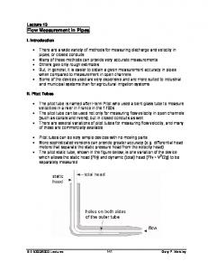
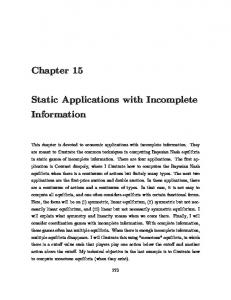
An elbow in a pipe can be used as a flow measuring device much in the same way as a venturi or orifice plate The head differential across the elbow (from inside to outside) is measured, and according to a calibration the discharge can be estimated The taps are usually located in the center of the elbow (e.g. at a 45° angle for a 90° elbow), but can be at other locations toward the upstream side of the elbow Some companies manufacture elbow meters for flow measurement, but almost any pipe elbow can be calibrated Elbow meters are not as potentially accurate as venturi, nozzle, and orifice meters Typical accuracy is about ±4% of Q One advantage of elbow meters is that there need not be any additional head loss in the piping system as a result of flow measurement The graph below is a sample calibration curve for a 1½-inch elbow meter in a USU hydraulic lab where the head differential (inside to outside tap) is measured in inches of mercury, using a manometer (data are from Dr. L.S. Willardson) Calibration for a 1.5-inch Elbow Meter
4.0
Head differential (inches of Hg)
3.5
3.0
2.5
2.0
1.5
1.0
0.5
0.0 0.00
0.02
0.04
0.06
0.08
0.10
0.12
0.14
Discharge (cfs)
BIE 5300/6300 Lectures
153
Gary P. Merkley
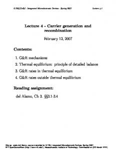
II. Variable Area Meters • •
•
These are vertical cylinders with a uniformly expanding cross-section in the upward direction A float inside the cylinder stabilizes at a certain elevation depending on the flow rate through the cylinder
Note that the outside walls are usually transparent to allow direct readings by eye
III. Horizontal Trajectory Method •
From physics, an accelerating object will travel a distance x in time t according to the following equation (based on Newton’s 2nd law):
a t2 x = vot + 2
(1)
where x is the distance; vo is the initial velocity at time 0; t is the elapsed time; and a is the acceleration • • • •
Flow emanating from a horizontal pipe will fall a height y over a distance x The horizontal component (x-direction) has almost no acceleration, and the vertical component (y-direction) has an initial velocity of zero The vertical acceleration is equal to the ratio of weight to mass, or g = 9.81 m/s2 (32.2 ft/s2) Therefore,
x = v ot
Gary P. Merkley
and, y =
154
gt 2 2
(2)
BIE 5300/6300 Lectures
•
Then by getting rid of t, knowing that Q = VA, and the equation for the area of a circle, the flow rate is calculated as follows:
π D2 x Q= 2y 4 g
(3)
where D is the inside diameter of the circular pipe
• • • • • •
This equation is approximately correct if x and y are measured to the center of mass of the discharge trajectory Errors occur because in practice it is difficult to measure exactly to the center, and because of possible wind and other turbulent effects Also, the pipe might not be exactly horizontal (although a correction could take this into account, according to the same analysis given above) Tables of coefficient values derived from experiments allow x and y to be measured from the top of the trajectory However, measurements can be difficult because the flow is often very turbulent at a distance from the pipe end The previous equation can be simplified as:
Q = 3.151CD2
x y
(4)
where C is a coefficient to adjust the calculated discharge value when the ratios of x/D or y/D are smaller than 8 and 5, respectively (otherwise, C equals unity) • •
Equation 4 is valid for x, y and D in ft, and Q in cfs The following table is for C values for use with Eq. 4
BIE 5300/6300 Lectures
155
Gary P. Merkley
y/D 0.5 1.0 2.0 3.0 4.0 5.0 •
1.00 1.44 1.37
1.50 1.28 1.24 1.11
2.00 1.18 1.17 1.09 1.04 1.01 0.97
x/D 2.50 3.00 1.13 1.10 1.12 1.09 1.08 1.07 1.04 1.04 1.01 1.02 0.99 1.00
4.00 1.06 1.06 1.05 1.04 1.03 1.01
5.00 1.03 1.03 1.03 1.03 1.02 1.01
8.00 1.00 1.00 1.00 1.00 1.00 1.00
This method can also be used for pipes flowing partially full (i.e. A < πD2/4), and experimental data are available to assist in the estimation of discharge for these conditions
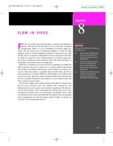
IV. California Pipe Method • • •
This is the horizontal pipe method for partially-full pipes It is somewhat analogous to the calibration for a weir or free overfall The following equation is in English units: 1.88
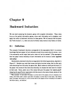
a⎞ ⎛ Q = 8.69 ⎜ 1 − ⎟ ⎝ D⎠
D2.48
(5)
where a and D are defined in the figure below (ft); and Q is discharge in cfs
• • • • •
The ratio a/D is limited to: a/D > 0.45 This method was published in the 1920’s Measurement accuracy is only ±10%, at best The pipe must be exactly horizontal (level), with circular cross section The pipe must discharge freely into the air, unsubmerged
Gary P. Merkley
156
BIE 5300/6300 Lectures
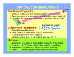
V. Vertical Trajectory Method • • •
As with pipes discharging horizontally into the air, there is a method to measure the flow rate from vertical pipes This is accomplished by assuming a translation of velocity head into the measurable height of a column of water above the top of the pipe Thus, to estimate the flow rate from pipes discharging vertically into the air it is only necessary to measure the: 1. inside diameter of the pipe, D; and, 2. the height of the jet, H, above the pipe
• • •
This is a nice idea on “paper,” but in practice, it can be difficult to measure the height of the column of water because of sloshing, surging, and splashing Also, the act of measuring the height of the column can significantly alter the measured value The table below gives flow rate values in gpm for several pipe diameters in inches Jet Pipe Diameter (inch) Height 2 3 4 5 6 8 10 12 (inch) (gpm) (gpm) (gpm) (gpm) (gpm) (gpm) (gpm) (gpm) 2 28 57 86 115 150 215 285 355 2½ 31 69 108 150 205 290 385 480 3 34 78 128 183 250 367 490 610 3½ 37 86 145 210 293 440 610 755 4 40 92 160 235 330 510 725 910 4½ 42 98 173 257 365 570 845 1060 5 45 104 184 275 395 630 940 1200 6 50 115 205 306 445 730 1125 1500 7 54 125 223 336 485 820 1275 1730 8 58 134 239 360 520 890 1420 1950 9 62 143 254 383 550 955 1550 2140 10 66 152 268 405 585 1015 1650 2280 12 72 167 295 450 650 1120 1830 2550 14 78 182 320 485 705 1220 2000 2800 16 83 195 345 520 755 1300 2140 3000 18 89 208 367 555 800 1400 2280 20 94 220 388 590 850 1480 2420 25 107 248 440 665 960 1670 2720 30 117 275 485 740 1050 1870 3000 35 127 300 525 800 1150 2020 40 137 320 565 865 1230 2160 From Utah Engineering Experiment Station Bulletin 5, June 1955. “Jet Height” (first column) is the height from the top of the pipe to the top of the jet.
BIE 5300/6300 Lectures
157
Gary P. Merkley
VI. Vortex Shedding Meters • •
• • •
The vortex shedding meter can be accurate to within ±½% to ±1% of the true discharge The basic principal is that an object placed in the flow will cause turbulence and vortices in the downstream direction, and the rate of fluctuation of the vortices can be measured by detecting pressure variations just downstream
This rate increases with increasing velocity, and it can be used to give an estimate of the discharge This requires calibration for a particular pipe material, pipe size, element shape and size, fluid type, and temperature It is essentially a velocity-area flow measurement method, but it is calibrated to give discharge directly
Gary P. Merkley
158
BIE 5300/6300 Lectures
•
• • • • •
Vortex shedding meters are commercially available and are used with a variety of fluids, not only with water, and can operate well over a large pressure range and high flow velocities Size selection for these meters is important in order to avoid cavitation There need not be any moving parts in the meter This meter can be used for velocities up to approximately 50 m/s, or 180 kph The response of the device is linear for Reynolds numbers of 10,000 or more Errors can result from pipe vibration due to external machinery or other causes, or when the velocity is too low; however, some sophisticated devices have been developed and tested to correct for such errors
VII. Ultrasonic Meters 1. Doppler • • •
An emitted pressure wave reflects off a deflector plate Difference between transmitted and reflected frequencies correlates to flow velocity Liquid does not have to be clean – in fact, it may not work well if the liquid is “too clean” because it needs particles to reflect the signal
2. Transit-time • • • •
Also called “time-of-flight” The liquid should be fairly clean with this method Devices generates high-frequency (≈1 MHz) pressure wave(s) Time to reach an opposing wall (inside the pipe) depends on: a) Flow velocity b) Beam orientation (angle) c) Speed of sound through the liquid medium
• •
Upstream straightening vanes may be needed to avoid swirling flow May have a single or multiple transmitted sound beams
VIII. Other Measurement Devices • • • •
Collins meters Commercial propeller flow meters Electromagnetic flow meters Volumetric tank
BIE 5300/6300 Lectures
159
Gary P. Merkley
•
Weight tank
References & Bibliography Brater, E.F. and H.W. King. 1976. Handbook of hydraulics. McGraw-Hill. Daugherty, R.L. and J.B. Franzini. 1977. Fluid mechanics with engineering applications. McGraw-Hill. Ginesi, D. 1987. Putting new technology to work in flow measurement. Chilton’s I&CS 60:2:25-28. Greve, F.W. 1928. Measurement of pipe flow by the coordinate method. Purdue Engrg. Experiment Station Bulletin #32. Israelson, O.W. and V.E. Hansen. 1962. Irrigation principles and practices. John Wiley, 3rd Ed., pp. 140-145. King, L.G. 1974. Drainage laboratory manual. BIE Dept., USU (BIE 605 course notes). Ledoux, J.W. 1927. Venturi tube characteristics. Trans. ASCE, vol. 91. Lucas, G.P. and J.T. Turner. 1985. Influence of cylinder geometry on the quality of its vortex
shedding signal. Proc. Int’l Conference on Flow Measurement (FLOWMECO 1985), Univ. of Melbourne, Australia, pp. 81-89. Miller, R.W. 1996. Flow measurement engineering handbook. 3rd Ed. McGraw-Hill Book Co., New York, N.Y. Sovik, R.E. 1985. Flow measurement - some new considerations. Mech. Engrg., May, 107(5):48-52. Tily, P. 1986. Practical options for on-line flow measurement. Process Engrg., London, 67(5):85-93. U.S. Bureau of Reclamation. 1981. Water measurement manual. 2nd Ed., Denver, CO.
Gary P. Merkley
160
BIE 5300/6300 Lectures