P-code Generator FPGA Design for Direct GPS P (Y)-Code Acquisition Jing Pang 1, Janusz Starzyk 2 1
Department of Electrical Engineering and Computer Science, Ohio University, Athens OH 45701, U. S. A.
[email protected] 2 Department of Electrical Engineering and Computer Science, Ohio University, Athens OH 45701, U. S. A.
[email protected]
Abstract. Direct GPS P (Y)-code acquisition is necessary when GPS C/A code signal is denied. Since the acquisition process is a two-dimensional search in time domain and frequency domain, a successful correlator design with a local P-code generator as reference is very important. As a new programmable technology, FPGA is a good choice for digital system prototyping and design. Especially Xilinx Virtex chip DLL feature is appropriate for GPS application since GPS is a time based ranging system. However, due to the extremely long sequence of P-code, it is a challenging task to efficiently design and verify Pcode generator using HDL (hardware description language) and commercial CAD tools. In this paper, an equivalent GPS P-code simulator model is proposed to facilitate design and verification. In addition, a group of mathematical equations are developed to implement a flexible P-code generator, which can start running from any specific time of a week. As a result, it can be extended to massive parallel correlator design for direct GPS P (Y)code acquisition application.
1 Introduction The Global Positioning System (GPS) is a worldwide satellite navigation system, which consists of a constellation of 24 satellites and their ground stations. GPS signals are specially coded satellite signals that can be processed in a GPS receiver. When receiving the signals from at least 4 satellites, by measuring the travel time of a signal transmitted from each satellite, a receiver can determine latitude, longitude, altitude, time, and velocity of the receiver [1][2][3]. Each satellite transmits two signals: L1 (1575.42 MHz) and L2 (1227.60 MHz). L1 is modulated by the P (precision) code and the C/A (coarse/acquisition) code. C/A code is a 1023 chip long pseudo-random number (PRN) sequence sent at a rate of 1.023 megabits/sec [4]. The L1 Coarse Acquisition (C/A) Signal provides the Standard Positioning Service (SPS) with a predictable positioning accuracy of 100 meters (95 percent) horizontally, 156 meters (95 percent) vertically and time transfer accuracy to UTC within 340 nanoseconds (95 percent). L2 carrier only carries P code.
P-code is 2.3547*10^14 chip long with a broadcast rate of 10.23 Mega-chips per second. Actually it is broken into 37 pieces (one for each satellite) and restarted every week so that each piece has a period of 7 days. Each satellite transmits a unique code, allowing the receiver to identify the signals so that multiple users can get access to GPS signals. GPS signal acquisition is defined as a process to detect the presence of the GPS signal. Traditionally, the GPS receiver locks onto the C/A code to extract the 50 bitper-second navigation data message. Hand-over-word (HOW) in navigation data message provides necessary timing information. Then, starting from HOW, acquisition is transferred to P-code acquisition part [5]. Once the access to the C/A code signals is denied, the direct P (Y) acquisition is needed. With poor knowledge of time, massive parallel correlator is very important for a successful P (Y) Direct receiver design [6]. As a result, a good P-code generator is a critical design component. If parallel P-code generator design is available, each running from a specific time of a week, it’s possible to search a large time interval so that fast P (Y) code acquisition can be obtained. This paper presents a new method to design P-code generator in FPGA technology. First, GPS technology is briefly introduced in part 1. Then, the theoretical basis for Direct GPS P-code acquisition is described in part 2. Next, P-code generator architecture is provided in part 3. In addition, a GPS P-code generator tuning model is proposed in part 4. P-code structure is analyzed and chip relationship is characterized so that a flexible P-code generator can start running at any specific time of a week. In part 5, an equivalent GPS P-code generator simulator is illustrated. It is extremely useful for prototyping at initial design stage and good for design verification. At the final verification stage of real GPS p-code generator design discussed in part 6, two cases are used to test the code halting at x1epoch, x2epoch generation and the end of week. FPGA implementation results are described in part 7.
2 Direct GPS P-code Acquisition Conventionally, GPS P-code acquisition is achieved by first acquiring a shorter C/A code to obtain navigation data message, which enables time synchronization for subsequent acquisition of the P(Y) code. Direct GPS P-code acquisition is necessary in case the access to C/A code is denied. The key is to obtain extremely accurate time and frequency for the receiver, or use massive parallel P-code correlator. In reality, knowledge of accurate time and frequency is often limited, so the latter method is quite often used for direct GPS P-code receiver design. GPS signals are written as following:
S L1 (t ) = Ap1 P(t )D(t ) cos(2π f1 t + φ1 ) + Ac C(t )D(t )sin(2π f1 t + φ1 ) S L 2 (t ) = Ap 2 P(t )D(t ) cos(2π f 2 t + φ 2 )
(1) (2)
C i ( t ) = G 1 (t )G 2 (t + n i T c )
(3)
Pi ( t ) = X 1 (t )X 2 [ t + (i − 1)T p ] where
(4)
A p1 and A p1 are the P-code and C/A code amplitude on the GPS signals
S L1 and S L 2 at L1 and L2 frequency. P(t) and C(t) represent P-code and C/A code respectively, D(t) is navigation data, f1 and f 2 correspond to L1 and L2 which are
φ1 and φ 2 are L1 and L2 carrier phase, Tc is C/A-code chip length, and T p is P-code chip length, i corresponds to each satellite, and each satellite carrier frequency,
has different ni . Each satellite uses a unique code sequence to implement the CDMA technique for multiple user access. Acquisition is a carrier and code phase two-dimensional search process [7]. The autocorrelation function of a P code is as following:
R
P
(τ ) =
∫
∞ − ∞
P i (t )P i (t + τ
)dt
(5)
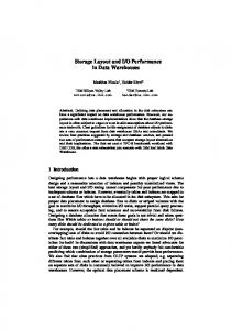
where Pi is the P code for the ith satellite and τ is phase of the time shift. The correlation peaks repeat every code period. The property of the autocorrelation function is used to synchronize the receiver replicated code with the received code. It is important that the cross-correlation of any two P codes are minimal for any phase or Doppler shift over the entire code period. A typical acquisition block diagram is shown in the following figure: I channel correlation
( * )^ 2
Digital IF
comparator correlation
( * )^ 2 threshold
Sine Cosine Local Oscillator
P-code generator
>= 0 Acquire signal < 0 Repeat acquiring Acquisition Algorithm
Fig. 1. Direct GPS P (Y) Code Acquisition Diagram Typical acquisition technique includes successive code phase and carrier frequency search to find a correlation peak with maximum correlation energy I 2 + Q 2 . The receiver detects a correlation peak by comparing the correlation amplitude against a preset threshold [8].
Although the whole architecture can be possibly implemented using FPGA technology, this paper will focus on the design and verification of P-code generator part. The design method is useful for extremely long sequence GPS P-code application and can also be applied to other DSP applications. So this work is valuable for prototyping designs with long output sequences, which are normally difficult to verify and test.
3 GPS P-Code Generator Architecture Each Pi (t ) is the Modulo-2 sum of X 1 and X 2 i clocked at 10.23 Mbps. X1A, X1B, X2A and X2B are 12-stage LFSRs (linear feedback shift registers). X1A and X2A are each shorted to 4092 chips. X1B and X2B are each shorted to 4093 chips. X 1 is generated by the Modulo-2 sum of the outputs of X1A and X1B. When the X1A short cycles are counted to 3750, the X1 epoch is generated. The X2A and X2B shift registers operate in a similar manner to the X1A and X1B shift registers. First produce X 2 sequence by the Modulo-2 sum of the outputs of X2A and X2B, and then delay it by a selected integer number of chips, i, ranging from 1 to 37, which results in the X 2 i sequences [9]. The polynomials for X1A, X1B, X2A and X2B LFSRs can be written as: X 1 A : 1 + X 6 + X 8 + X 11 + X 12
(6)
X 1B : 1 + X + X + X + X + X + X 1
2
5
8
9
10
+X
11
+X
12
X 2A : 1 + X + X + X + X + X + X + X + X + X + X 3
4
5
7
8
X 2B : 1 + X + X + X + X + X + X 2
3
4
8
9
9
10
12
11
(7) 12
(8) (9)
The block diagrams of four LFSRs are similar. For example, X1A LFSR is shown in Fig. 2:
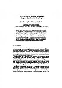
1 | 2 | 3 | 4 | 5 | 6 | 7 | 8 | 9 | 10 | 11 |12 | Fig. 2. X1A LFSR Diagram The block diagram of P-code generator is showed in Fig. 3. At the beginning of the GPS weekly period, X1A, X1B, X2A and X2B shift registers are initialized to produce the first chip of the week. The precessing of the shift registers with respect to X1A continues until the last X1A period of the GPS week interval. During this particular X1A period, X1B, X2A and X2B are held when reaching the last state of their respective cycles until that X1A cycle is completed. At this point, all four shift registers are initialized and provide the first chip of the new week.
Fig. 3. GPS P-Code Signal Generator
4 GPS P-code Generator Tuning Model After 4092 chips, X1A finishes a cycle and generates a setx1aepoch pulse. X1B needs to produce 4093 chips in a cycle to generate a setx1bepoch pulse. After 3749 X1B cycles, X1B is halted and it will be resumed when X1A reaches 3750 clock cycles. At that time, an x1epoch is generated. So totally X1B is halted by X1A for (4092-3749)=343 chip in one x1epoch cycle. Similarly, X2A has similar relationship corresponding to X2B as that of X1A versus X1B. The difference is that X2A and X2B are halted 37 extra chips in each x2epoch. The last week final halting is specified in ICD200 table and easy to look up. At any specific time during a week, the number of chips generated by X1A generator can be easily calculated because clock frequency is equal to 10.23MHz. Then the number of chips can be described as following:
Numchip = Time [s] * 10.23 [MHz]
(10)
In order to tune P-code generator in a specific time during a week, each LFSR (linear feedback shift register must be fed with specific initial vectors. In addition, all of the division blocks should be initialized properly. The following mathematical model is developed for this purpose: Numchip= 4092*3750* y1a + 4092* x1a + z1a = 4092* 3750* y1a + 4093* x1b + z1b = (4092* 3750+ 37) * y2a + 4092* x2a + z2a + dv = (4092* 3750+ 37) * y2a + 4093* x2b + z2b, x1b = 3748 and z1b = 4092 when (Numchip− 4092* 3750* y1a) ≥ (4093* 3749), x2a = 3749 and z2a = 4091 when (Numchip− 4092* 3750* y2a − 37* y2a) ≥ (4092* 3750), dv = 0 when ( Numchip− 4092* 3750* y2a − 37* y2a) < (4092* 3750), x2b = 3748 and z2b = 4092 when ( Numchip− 4092* 3750* y1a) ≥ (4093* 3749), 0 ≤ x1a ≤ 3749, 0 ≤ x2a ≤ 3749, 0 ≤ x1b ≤ 3748, 0 ≤ x2b ≤ 3748, 0 ≤ z1a ≤ 4091, 0 ≤ z1b ≤ 4092, 0 ≤ z2a ≤ 4091, 0 ≤ z2b ≤ 4092, 0 ≤ y1a ≤ 403199, y2a ≥ 0 , 0 ≤ dv ≤ 37
(11) where x1a, z1a, y1b, x1b, z1b, y2a, x2a, z2a, y2b, x2b, and z2b are integers. y1a loads the z-counter; x1a and x2a load 3750 division circuit in X1A and X2A; x1b and x2b load 3749 division circuit in X1B and X2B; z1a, z1b, z2a and z2b initialize XlA, X1B, X2A, and X2B LFSRs. So, in order to tune P-code to a specific time of a week, first solve above parameters corresponding to that specific time. Then initialize the P-code generator. Suppose Numchip is known. First use Numchip modular (4092*3750) to get quotient y1a and remainder 1. Then use remainder 1 modular 4092 to get x1a and z1a. When solving x1b and z1b, halting scenario should be considered. If (Numchip – 4092*3750*y1a) is greater than (4093*3749), then X1B LFSR will be halted so that x1b=3748, and z1b=4092. On the other hand, if (Numchip- 4092*3750*y1a) is less than (4093*3749), then x1b and z1b can be solved in modular method. Compared with X1A and X1B LFSRs, X2A and X2B LFSRs have 37 extra chip halting delays. Let’s first figure out how to solve y2a, x2a and z2a first. Use Numchip modulo (4092*3750+37) to get quotient y2a and remainder 2. If remainder 2 is greater than 4092*3750, then x2a=3749 and z2a=4091 and dv can be solved. Otherwise dv=0, so x2a and z2a can be solved in modular method.
Furthermore, use above results to solve x2b and z2b. If remainder 2 is greater than (4093*3749), then X2B LFSR will be halted so that x2b=3748 and z2b=4092. Otherwise
R = Numchip − ( 4092 * 3750 + 37 ) * y 2 a − dv = 4093 * x 2 b + z 2 b
(12)
Since y2a, dv and Numchip are known in equation (12) are known, R can be solved. At last, use modular operation again to solve x2b and z2b.
5 Equivalent GPS P-code Generator Simulator Algorithm described in Part 4 solves the problem of tuning P-code generator to any specific time of a week. Another design challenge is how to verify that a developed Pcode generator functions correctly. The extremely long period of P-code makes verification very hard. In this section, an equivalent simulator model is proposed to solve this problem. An equivalent hardware architecture in Fig. 4 is used to generate shorter code sequence which can be easily verified and then extend verification results to the original problem. The design strategy used in Fig. 4 is to minimize counting cycles while keeping the same 4092 short cycles for X1A and X2A LFSRs, 4093 short cycles for X1B and X2B LFSRs. The divisions 3750 blocks are modified as division 3 blocks. Correspondingly, the divisions 3749 blocks are modified as division 2 blocks. Moreover, the division 403120 z-counter block is minized as division 3 blocks. In this way, the overall cycles are greatly decreased, but the main halting and resuming features are still kept. So this architecture is flexible and easy to test.
Fig. 4. Short Sequence Signal Simulator Once the above shorter sequence generator functions correctly, it can be simply modified by replacing the small number division blocks with the larger number division blocks. In HDL code, it is very easy to do so. The verification of each single LFSR design is according to the following table [9]: Code X1A X1B X2A X2B
Chip Number 4091 4092 4092 4093 4091 4092 4092 4093
Vector State (HEX) 100010010010 (892) 000100100100 (124) 100101010101 (955) 001010101010 (2AA) 111001001001 (E49) 110010010010 (C92) 000101010101 (155) 001010101010 (2AA)
Vector State for 1st Chip following Epoch (HEX) 001001001000 (248)
Table 1. Final Code Vector States
010101010100 (554) 100100100101 (925) 010101010100 (554)
Apply input vector of the 1st chip, and then observe what are the output vectors of the 4091, 4092 or 4093 chips compared with those in Table 1. Other verification concern is the halting and resuming of X1B, X2A and X2B at each epoch and also the chip generation at final week. In equivalent P-code generator simulator, after one cycle of x1epoch, X1B is halted for (4092-2)=4090 chips. Moreover, after one cycle of x2epoch, X2A is halted for 4 chips and X2B is halted for 4094 chips. At the end of a week, X2A is halted for 4084 chips and X2B is halted for 4082 chips. At the end of week, there are 3 x1epochs since z-counter is a dividing by 3 counter. Since X2A is halted for 4 chips every x1epoch cycle, at the end of week, the halting of X2A can be calculated according to the remainder of (4092*3-2*4) modulo 4092, which is equal to 4084 chips. Similarly, the halting of X2B corresponds to the remainder of (4092*3-2*4) modulo 4093, which is equal to 4082 chips.
6 GPS P-code Generator Design Verification Once previous equivalent GPS P-code generator simulator passes verification, only the numbers of divisions (those constants) need to be changed to accomplish a P-code generator design. Now, it’s time to finally verify GPS P-code generator. Case 1: Verification of code halting after one cycle of X1A, X1B, X2A and X2B. In equation (11), assume y1a=y1b=y2a=y2b=dv=0. Suppose x1b = 3748 and z1b = 4092. Then use algorithm described in part 4 to solve equation (11). As a result, x1a = 3749, z1a = 3748, x2a=3749, z2a=3748, x2b=3748, and z2b=4092. Use these parameters to setup P-code generator as that shown in Table 2. X1A X1B X2A X2B
LFSR 3748th vector 4092nd vector 3748th vector 4092nd vector
Division by 3750 or 3749 block 3749 3748 3749 3748
z-counter 0
Table 2. Case 1 P-code generator initialization table After one cycle of X1A, X1B, X2A and X2B, the simulation should show that X2AQ is halted for 37 chips, X1BQ is halted for 343 chips, and X2BQ is halted for 380 chips. X1AQ, X1BQ, X2AQ, and X2BQ are the 12th bit of the output vectors of X1A, X1B, X2A, and X2B LFSR. Case 2: Verification of code halting at the end of week. At the end of week, assume y1a=403199, x1a=3748, and z1a=3022. Solve equation (11) to get x1b = 3747, z1b = 3367, x2a=102, z2a=4091,x2b=102, and z2b=3989. Use these parameters to setup Pcode generator listed in Table 3.
X1A X1B X2A X2B
LFSR 3022nd vector 3367th vector 4091st vector 3989th vector
Division by 3750 or 3749 block 3748 3747 102 102
z-counter 403199
Table 3. Case 2 P-code generator initialization Table
Fig. 5. Case 2 simulation waveform
Fig. 6. The final X2AQ chip generation at the end of a week
Fig. 7. The final X1BQ chip generation at the end of a week
Fig. 8. Resume of X1AQ, X1BQ, X2AQ and X2BQ at the start of week Fig. 5-8 show the overall simulation results, and especially the halting timing is marked. In above waveforms, 10 ns clock period is used for functional verification. zcounter is initialized with signal ZNTINIT equal to 403199. X1ADIVINIT, XIBDIVINIT, X2ADIVINIT, and X2BDIVINIT are preloading values for X1A 3750 division block, X1B 3749 division block, X2A 3750 division block and X2B 3749 division block respectively. For example, X2BDIVINIT is equal to 102.
In addition, X1AINIT, X1BINIT, X2AINIT, and X2BINIT are initial vectors for X1A LFSR, X1B LFSR, X2A LFSR and X2B LFSR. For example, X1A LFSR is preloaded by hex vector 2E6, which is (3748+1)th vector in X1A 12-bit LFSR shortcycled 4092 output vector sequences. From simulations in Fig. 7 and Fig. 8, at the end of a week, X1BQ is halted for (51625-48185)/10 – 1 = 343 chips. According to Fig. 6 and Fig. 8, X2AQ is halted for (51625 - 40925)/10-1 = 1069 chips. Moreover, X2BQ is halted for (51625-41965)/101=965 chips according to Fig. 5 and Fig. 8. The table 4 [9] lists timing sequence generated during the last setx1aepoch at the end of week and is used to compare with the simulation results above. Signal setx1aepoch is generated after each cycle of X1A, which is equal to 4092 chips. Since simulation in Fig. 5~Fig. 8 starts one setx1aepoch cycle earlier than that listed in Table 4, when X1A generates the 3022nd chip, X1B, X2A and X2B generates its 3367, 4091 and 3989 chip respectively. According to Table 4, X1BQ should be halted for (4092-3749)=343 chips, X2AQ should be halted for (4092-3023)=1069 chips, and X2BQ should be halted for (4092-3127)=965 chips. The simulation results are same with those expected from Table 4.
Time
X1A-Code 1 … 3023 … 3127 … 3749 … 4092
Code Chip X1B-Code X2A-Code 345 1070 … … 3367 4092 … … 3471 4092 … … 4093 4092 … … 4093 4092
X2B-Code 967 … 3989 … 4093 … 4093 … 4093
Table 4. P-code Reset Timing (Last 400 usec of 7-day period)
7 FPGA Implementation In digital design, the clock distribution is very important, especially for GPS application, which is a time-based ranging system. FPGA is easy to use and has quick time-to-market turn around. Especially, Xilinx Virtex FPGA technology provides onchip Delay-Locked Loop (DLL) circuits which provide zero propagation delay and low clock skew between output clock signals distributed throughout the device [10]. This improves system level design and good for P-code generator design work. In addition, Virtex devices have 50,000 to 1,000,000 system gates. They have flexible on-chip RAMs and dedicated carry logic for high-speed arithmetic, dedicated
multiplier support, cascade chain for wide-input functions, and internal 3-state busing [11]. So in this paper, Virtex device is chosen to finally implement a GPS P-code generator for direct GPS P (Y)-Code Acquisition. The basic building block of the Virtex CLB is the logic cell (LC). An LC includes a 4-input function generator, carry logic, and a storage element. Each Virtex CLB contains four LCs, organized in two similar slices. The design is synthesized and implemented successfully. The total resource consumed on V800BG432-4 is as following: Number of External GCLKIOBS: 1 out of 4 25% Number of SLICES 175 out of 9408 1% The average connection delay for this design is 2.331 ns. The Maximum Pin Delay is 10.446 ns. The average connection delay on the 10 worst nets is 6.637 ns. Clock speed: 40 MHz The P-code generator is only a part of a P-code acquisition system which will be prototyped on the Virtex chip, and that’s why only a small portion (around 1%) of the chip was used.
7 Conclusion In this paper, an equivalent GPS P-code simulator model is proposed to facilitate the design and verification of a flexible GPS P-code generator for direct GPS P (Y)code acquisition using FPGA technology. Instead of considering the one-week long period of P-code, it uses much shorter sequence to verify the hardware design functions. It is important to know the relative chip relationship among X1A, X1B, X2A, and X2B LFSRs since P-code is the XOR of LFSR outputs. In this paper, a mathematical model is presented to locate X1A, X1B, X2A, and X2B output chips on any specific time of a week. According to equation (11) described in this paper, different halting phenomena can be further tested for shorter simulator model. Once the design passes verification, it can be easily modified into a real P-code generator design. The next task is to further verify the functionality of real P-code generator. By using initializing vectors for different functional blocks, P-code generator can start running at any specific time of a week. Two special cases are selected to verify the special halting phenomena. Then, the simulation results are compared with theoretical analysis and ICD 200 documents. Xilinx Virtex FPGA technology is good for hardware design implementation because it has zero-delay DLL with low skew rate. Also it provides lots of hardware resources. The implementation resource consumption is reported. Since this P-code generator design can start running at any specific time of a week, it can be easily
extended for massive parallel correlator design, which is very important for direct fast GPS P(Y)-code acquisition [12]. Furthermore, the design concept proposed in this paper can be applied to the whole direct GPS P(Y)-code receiver design and also other long sequence DSP applications. In addition, since only a small portion of chip is used, the future design task is to integrate the whole GPS-receiver design on a chip, which features a fast GPS P-code receiver.
References 1. Elliott Kaplan, Understanding GPS: Principles and Applications, Artech House, 1996 2. B. Parkinson, J. Spilker Editors, Global Positioning System: Theory and Applications Volume I, American Institute of Aeronautics and Astronautics, Washington, DC, 1996 3. van Leeuwen, J. (ed.): Computer Science Today. Recent Trends and Developments. Lecture Notes in Computer Science, Vol. 1000. Springer-Verlag, Berlin Heidelberg New York (1995) 4.2001 GPS SPS Performance Standard, http://www.navcen.uscg.gov/gps/geninfo/ 2001SPSPerformanceStandardFINAL.pdf 5. David M. Lin, James B. Y. Tsui, Dana Howell, “Direct P(Y)-Code Acquisition Algorithm for Software GPS Receivers”, The Proceeding of ION International Technical Meeting 1999, pp. 363, Nashville, Tennessee, Sept. 1999 6. Alison Brown and Neil Gerein, “Direct P(Y) Code Acquisition Using Electro-Optic Correlator”, The Proceedings of ION National Technical Meeting 2001, Long Beach, CA, Jan. 2001 7. J. B. Lozow, “Analysis for Direct P(Y)-Code Acquisition,” NAVIGATION, Journal of The Institute of Navigation, Vol. 44, No. 1, pp. 89-98, Spring 1997 8. M.S. Braasch, A. J. van Dierendonck, “GPS receiver architectures and measurements”, Proceedings of the IEEE, vol. 87/1, Jan. 1999 9. Global Positioning System Interface Control Document (ICD-GPS-200c), http://www.spacecom.af.mil/usspace/gps_support/documents/ICD-GPS-200RC-004.pdf 10. Using the Virtex Delay-Locked Loop, Xilinx Application Note: Virtex Series, Sept. 20, 2000 11. The Programmable Logic Data Book 2001, Xilinx Publication, 2001 12. Hugo Fruehauf, “A Better Way of Life for PPS Users … GPS SAASM and P (Y)-Direct, the New Wave of Military Receiver Technology for the PPS Navigation and Time and Frequency User”, The Proceedings of the Precise Time And Time Interval (PTTI) Systems and Applications, Dana Point, CA, Dec., 1999