IEEE JOURNAL OF QUANTUM ELECTRONICS, VOL 29 NO 5 MAY 1993. Linewidth ... John M. Iannelli, Y. Shevy, J. Kitching, and Amnon Yariv, Fellow, ZEEE.
I
I253
IEEE JOURNAL OF QUANTUM ELECTRONICS, VOL 29 NO 5 M A Y 1993
Linewidth Reduction and Frequency Stabilization of Semiconductor Lasers Using Dispersive Losses in an Atomic Vapor John M . Iannelli, Y . Shevy, J. Kitching, and Amnon Yariv, Fellow, ZEEE
Abstract-The effects of a dispersive loss on the linewidth and chirp of a semiconductor laser are discussed. A van der Pol analysis is used to obtain expressions for linewidth reduction and chirp reduction in an arbitrary optical feedback configuration. Specifically the use of an atomic cesium vapor as a dispersive loss mechanism is considered. The dominant factor in reducing the linewidth and chirp is shown to be the frequencydependent phase change from the atomic vapor. However, we also show that under certain operating conditions the frequency-dependent amplitude changes from the atomic vapor also contribute to the reduction. The results are shown to be in agreement with a detailed rate equation calculation.
I. INTRODUCTION HE spectral purity of semiconductor lasers is a topic
T
of great interest. Due to the importance of the semiconductor laser linewidth in many device applications (interferometric fiber sensors, heterodyne detectors, coherent transmission systems) much effort has been devoted to its study and reduction. Fundamentally, the laser linewidth is a direct consequence of the diffusion of the phase of the optical field with time. In semiconductor lasers, one of the primary driving mechanisms of phase diffusion is spontaneous emission into the lasing mode. A limit derived by Schawlow and Townes [l] shows the linewidth to be inversely proportional to both the output power and the square of the optical.mode volume. Due to the small Q cavity of semiconductor lasers and the additional effect of amplitude to phase coupling described by the a parameter [2], linewidths are typically on the order of tens of MHz. Several methods have been proposed and demonstrated for reducing semiconductor laser linewidths. We have recently shown both theoretically and experimentally that the incorporation of a dispersive loss mechanism in the laser cavity can lead to a dramatic quenching of the spectral linewidth [3], [4].Due to the strong amplitude to phase coupling in semiconductor lasers, a dispersive loss can be used to reduce the linewidth by producing changes Manuscript received May 26, 1992; revised October 12, 1992. This work was supported by DARPA, ONR, and AFOSR. The work of J. Kitching was supported by NSERC Canada. The authors are with the Califomia Institute of Technology, Pasadena, CA 91125. IEEE Log Number 9207853.
in the field’s amplitude and phase which correct for the initial phase fluctuation. The key quantities in this method are the slopes of the loss rate and the accompanying refractive index versus frequency. The correct slope produces negative as opposed to positive feedback to phase fluctuations, the magnitude of the slope determines the strength of the correction signal, and in the case of amplitude changes, the CY parameter governs the coupling of the amplitude to the phase. Ironically, the amplitude to phase coupling mechanism which normally increases the linewidth by a factor of (1 a 2, (atypically in the range of 3-6) [2] can, in conjunction with a dispersive loss, be used as leverage for obtaining linewidth reduction. In addition to reducing the linewidth, a dispersive loss also improves the frequency stability through a reduction of adiabatic chirp. As will be discussed below, the frequency stability is improved with respect to changes in injection current as well as variations in other external parameters such as cavity length. It will also be shown that linewidth reduction and adiabatic chirp reduction are simply related to each other [ 5 ] . As stated above, the field corrections made by the dispersive loss are twofold. Analogous to the KramersKronig relations, arguments of causality dictate that amplitude changes must be accompanied by phase changes. The dispersive loss therefore introduces a frequency-dependent loss and a frequency-dependent refractive index to the laser cavity. Consequently, there exist two mechanisms for correction of phase fluctuations. It will be shown that these mechanisms can be naturally modeled through modifications of the real and imaginary parts of the laser’s complex susceptibility. The dispersive loss technique can be easily implemented using different schemes of optical feedback, such as the reflection from an external cavity [6]. The external optical feedback serves as an effective loss (gain) mechanism in the semiconductor laser cavity. In an external cavity laser, one of the laser facets is used with an external mirror to compose a coupled-cavity system thereby rendering the facet’s effective reflectivity (i.e., laser loss rate) frequency-dependent . When discussing the coupling of an external cavity to the laser cavity it is important to distinguish between internal and external losses. As will be discussed below, the external cavity can possess its
0018-9197/93$03.00 0 1993 IEEE
+
1254
own dispersive loss (external) but the dispersive loss the laser perceives (internal) will in general be different due to the coupling between the two cavities. In fact, in a simple external cavity laser the external loss only displays frequency-dependent phase changes while the internal loss is comprised of both frequency-dependent phase and amplitude changes. Both mechanisms have been shown to be instrumental in reducing the noise [4]. There is a tradeoff, however, in ordinary external cavity systems between linewidth reduction and effective bandwidth [8]. Relatively short cavities, having large effective bandwidths, can produce damping of relaxation oscillations but leave much to be desired in terms of linewidth reduction. To achieve substantial reduction one needs to employ long cavities and operate at relatively high feedback levels. Such conditions often lead to either mode hopping or multimode operation due to the closely spaced external cavity modes [9], [lo]. In this paper, we will show that these problems can be circumvented by increasing the slope of the loss rate versus frequency to allow operation at lower feedback levels and to improve mode discrimination. A frequently used technique is the formation of an external cavity with a high-Q confocal Fabry-Perot (CFP) cavity acting as the reflector [8], [ 1 1 1 . This method performs quite well in terms of noise reduction and mode discrimination by “locking” the laser frequency to the CFP cavity resonance. However, since the dispersive loss is related to the resonant reflection from the CFP cavity, variations in the locking frequency can occur from unavoidable thermal and mechanical instabilities. We have recently demonstrated an alternative method using an atomic resonance, useful for both its spectrally narrow bandwidth (i.e., large slope) and inherent frequency stability. We have chosen to use the Faraday rotation in an atomic cesium vapor as the dispersive loss mechanism. Through the use of counter-propagating pump and probe beams a doppler-free reflection with a power broadened bandwidth of -20 MHz is possible. Due to the small bandwidth of the reflection, small frequency variations in the laser field cause the dispersive loss to produce, in response, large changes in the field’s amplitude and/or phase which are then fed back to the diode via the external cavity. With this technique, linewidth reductions as large as 2000 have been demonstrated at relatively small feedback levels [4]. In the particular geometry of our system, one should exercise care when discussing linewidth reduction. An important distinction must be made between reduction due to the atomic dispersive loss and reduction due to the storage of energy in the external cavity. It has been shown [7] that in an external cavity laser the linewidth reduction behaves as the ratio of stored energy in the cavity to the stored energy in the diode. The fact that in the atomic vapor arrangement the linewidth reduction is due to the atomic dispersive loss and not a consequence of the stored energy in the external cavity has been verified experimentally [4].
IEEE JOURNAL OF QUANTUM ELECTRONICS, VOL. 29, NO. 5, MAY 1993
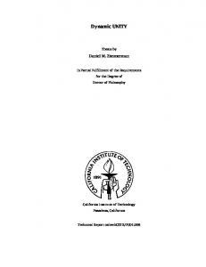
The purpose of this paper is to expand the theoretical framework for “locking” a semiconductor laser to the dispersive losses in an atomic vapor. The generic theory of noise reduction via dispersive losses is taken up in Section I1 through a van der Pol analysis. In Section I11 we compare the results of the van der Pol analysis to a detailed rate equation analysis specific to our system. Section IV gives the behavior of the lasing frequency and linewidth reduction under various conditions, as obtained through numerical simulations. The theory concentrates more on the semiconductor laser physics rather than on the effects within the atomic dispersive loss itself. The details of the atom-radiation field interactions will be presented elsewhere [ 121. 11. VAN DER POL ANALYSIS The configuration of coupling the dispersive loss to the laser diode via an external cavity is shown in Fig. 1 . In this three mirror configuration it is assumed that multiple reflections in the external cavity can be neglected since the feedback level is taken to be small. Within the external cavity is an atomic cesium cell placed between crossed polarizers which provides the dispersive loss [4], [ 131. The cesium transition being used is the 852.1 nm cycling transition between the F = 4 hyperfine level of 6 . ~ and ~ 1 ~ the F‘ = 5 hyperfine level of 6 p 3 / , (see inset). The application of a weak axial magnetic field introduces a circular birefringence in the vapor by removing the degeneracy within the hyperfine levels. When the laser frequency is in spectral proximity of the cesium transition the plane of polarization is Faraday rotated in the cell and a fraction of the field is transmitted through the second polarizer. After reflection from the external mirror, the beam is again passed through the cell and returned to the laser diode. In this arrangement the counter-propagating pump and probe beams are orthogonally polarized with respect to each other (see Fig. 1 ) . Through the use of a strong pump beam and weak crossed polarized probe beam it is possible to circumvent the Doppler broadening and obtain a spectrally narrow resonance [ 121. The cesium dispersive loss introduces both a frequency-dependent loss and refractive index to the laser cavity. It will be shown in Section IV that the loss is symmetric in frequency about the cesium linecenter while the refractive index is antisymmetric. These properties are critical since the process of linewidth reduction relies on the slopes of these two curves. To describe the effects of the dispersive loss we follow a van der Pol analysis in which the field intensity adiabatically follows the inversion density. For calculations of linewidth and chirp this treatment is justified [2]. The specific van der Pol analysis carried out below assumes that the dispersive loss is situated within the semiconductor laser cavity. Although our particular system configuration employs a loss mechanism external to the semiconductor, it will be shown that this calculation still provides the correct result for a loss introduced via an external optical feedback.
I
1255
IANNELLI ef u l . : SEMICONDUCTOR LASERS USING DISPERSIVE LOSSES
phase [4] 6 b *
8
-
A,(1
+ w 1 6 + A,C,+ + C,)+ - (
=
Aj/2wm
~ ~= 1 6- A r / 2 u m
(44 (4b)
where A , and Ai are the real and imaginary parts, respectively, of the Langevin noise source, and
F= 3
=m &Field
Cesium
LD
PY
PK
Fig. 1. Experimental arrangement for using Faraday rotation in atomic cesium as a dispersive loss mechanism. LD: Laser Diode, M: External Mirror. P: Polarizer. Inset shows the relevant energy levels under considerat ion.
We begin by taking the optical field as E(t)
=
[ A , + 6(f)l exp { i ( U m t + ~ ( 0 ) ) (1)
a’-
x P’ (3) Xi
In ( 2 ) one can observe that the photon lifetime enters the rate equation on the same footing as the complex susceptibility. Therefore, the dispersive loss can be more naturally described through modifications in x , as opposed to a complex lifetime. Assuming the effects of the dispersive loss are well within the linear regime (i.e., ignoring the effects of saturation in the loss mechanism described through x ( 3 ) ) , we can thus substitute
where A , is the field amplitude, 6 and cp are the smallsignal amplitude and phase ((+), = 0, in which ( ), indicates temporal averaging), respectively, and U, is the lasing frequency. As shown in [ 2 ] the coupled rate equation for amplitude and phase is given by We see that frequency-dependent amplitude and phase changes are described by C , in x and Cj in x : I ) , respectively. Physically, C, represents a frequency-dependent loss and C j a frequency-dependent refractive index change in the semiconductor laser cavity. To calculate the field spectrum linewidth we first calculate the autocorrelation function of the phase. This is readily obtained through Laplace transformation of 6 and cp [ 2 ] in (4) resulting in
I”
where the complex susceptibility x is expressed as a nonlinear function of the lasing field by x ( E ) = x‘” + x ‘ ~ [’ E l 2 .The cold cavity resonant frequency is given by U,, the nonresonant refractive index by p , and the photon lifetime by rP. A is taken to be a Langevin noise source which will represent spontaneous emission. Following [3], the dispersive loss is modeled by a frequency-dependent loss rate as
1
1
- =
-
TP
TPO
+ 2c+
(8)
where we have taken the correlations of the Langevin sources as
(3)
where C is a constant representing the slope of the loss curve, and the (instantaneous) lasing frequency is given by (U, + +). Since corrections to the loss rate are taken to occur instantaneously, the results of this analysis are valid only for frequencies smaller than the inverse of the longest response time of the system. This ansatz describes changes in the field’s amplitude due to the dispersive loss but not changes in the field’s phase. To further take into account the effects of phase changes in the loss rate C is defined as a complex number, C = C, iC,. Using this form of C in (3), we obtain the modified van der Pol equations for the amplitude and
+
min ( t l , t2)
and D (x) as the delta function. V is the resonator volume, is the dielectric constant, and ( n 2 / A n ) is the inversion factor. It should be noted that in this calculation of linewidth the noise source is taken to represent spontaneous E
c
1256
IEEE JOURNAL OF QUANTUM ELECTRONICS, VOL. 29, NO. 5. MAY 1993
emission (white noise) by choosing the noise correlation functions [(9)] to be delta-correlated in time. The field autocorrelation function is now written as
( E * ( t ) E ( t+
L
7))
+ K P ( ~- ~ ) e - "
After combining (8) and (12) and applying the WienerKhintchine theorem, we obtain a Lorentzian field spectrum with a spectral linewidth given by = AvS.T.
( t ) we write (16) as [7]
+
(1 CY2) aC, cj12
+
+
(1 A'S.T.
+ a2)
~
(13)
Q2
where AvS..,.. is the Schawlow-Townes linewidth [I] and Q = [I aC, + C,]. It should be stressed that C , and C, describe the frequency-dependent amplitude and refractive index changes within the diode cavity. These will be referred to as the internal dispersive losses. The above treatment therefore applies to an arbitrary laser configuration, one of which is our scheme of external optical feedback. As shown in (13), the field corrections made by the dispersive loss are twofold. An initial phase fluctuation causes a frequency shift in the laser field. On one hand, the dispersive loss will behave as a frequency discriminator and produce, in response, an amplitude change in the field described by C,. Through the a parameter this amplitude change corrects for the initial phase fluctuation. On the other hand, the frequency shift in the laser field will cause the dispersive loss to produce, in response, a phase change in the field which will directly correct for the phase fluctuation. This process is described by C , . Either separately or together, the two mechanisms reduce the rate of phase diffusion, thereby reducing the linewidth. Although frequency-dependent amplitude and refractive index changes both play a role in linewidth reduction, amplitude changes are weighted more heavily (for a > 1) since C , is multiplied by the a parameter.
(17)
where K is the feedback coupling rate defined by [9] K = n r / F r d , F , and T d are the diode cavity finesse and roundtrip time, respectively, and r is the external mirror reflectivity. The external cavity phase shift is given by 4 = w m 7 , T = 2L/c, being the round-trip time in the external cavity, and fl is the lasing frequency without feedback. The dispersive loss element in the external cavity is now modeled through a modification of K and r as
+
Static Operating Conditions To obtain expressions for C, and Cj we need to investigate the operating conditions for our particular system. We now write the optical field inside the diode cavity E ( t ) and its complex amplitude P ( t ) as E ( t ) = Re [ ( t )eiwarl]
0 (t) =
Jp