with off-nominal turns ratios used in power systems steady-state stud- ies. The conventional model of the load tap change transformer (LTC) is shown in terms of ...
Load Tap Change Transformers: A Modeling Reminder
Admittance Represented on the Nominal Winding Side: For the model of Figure 1, the following relationships can be obtained: I ik =
Luciano V. Barboza, Hans H. Zürn, Roberto Salgado Author Affiliation: Electrical Engineering Department, Federal University of Santa Catarina, Florianópolis, Brazil; Catholic University of Pelotas, Federal Center for Technological Education of Pelotas, Brazil. Abstract: This letter reviews the general model of transformers with off-nominal turns ratios used in power systems steady-state studies. The conventional model of the load tap change transformer (LTC) is shown in terms of the analytical expressions that represent this device. A general model incorporating the effects of the transformers with off-nominal turns ratios with the phase shifting transformers is presented. The differences between the alternative models, in which the admittance is represented either on the tap side or on the opposite tap side of the transformer, are explained. It is also shown that, if the admittance is represented on the tap side, its value must be suitably adjusted. An example illustrates the differences in terms of numerical results from these models. Keywords: Off-nominal turns ratio transformers, phase shifting transformers, general model. Introduction: The literature presents some models for the simulation of LTC transformers. Generally, transformers with off-nominal turns ratios and phase shifting transformers can be represented as an admittance (or impedance) in series with an ideal autotransformer with transformation ratio a:1 and ej φ:1, respectively. Referring to the different models shown in the literature, we note that the main difference between them is the side of the ideal transformer in which the admittance is represented. In [1]-[2], this admittance is represented on the side of the nominal winding. In [3]-[4] the admittance is represented on the off-nominal side. A third possibility, presented in this letter, is to divide the admittance into two parts, one for each side of the ideal transformer. This letter points out the differences between these models. LTC Transformers: An LTC transformer with nominal admittance yik is represented by an ideal transformer with turns ratio a:1 in series with this admittance. This model is shown in Figure 1. In this model the admittance is represented on the nominal side of the transformer, and thus its value is also nominal. From this figure, I E i = aE p = a − ki + E k y ik
(1)
I ki = − aI ik ,
(2)
1 1 yik E i − yik E k a2 a
(4)
1 yik E i + yik E k . a
(5)
I ki = −
The parameters A, B, and C for the equivalent circuit shown in Figure 3, are A=
a −1 1 1−a yik B = 2 yik C = yik . a a a
(6)
Admittance Represented on the Off-Nominal Winding Side: From Figure 2, I ik =
1 1 yik E i − yik E k a2 a
(7)
Figure 1. Equivalent circuit for LTC—total admittance on the nominal winding
Figure 2. Equivalent circuit for LTC—total admittance on the off-nominal winding
and
which combined provides Ei =
a2 I ik + aE k . yik
(3)
Equation (3) leads to the diagram shown in Figure 2. The diagrams shown in Figures 1 and 2 are equivalent. The difference between them is the side where the admittance is represented. From Figure 2 we note that, if the transformer admittance is represented on the off-nominal side, it must be multiplied by the inverse of the squared transformation ratio. This is interpreted as referring the admittance to the off-nominal side. Therefore, we conclude that for nominal turns ratio, the per unit value of the admittance is the nominal on both sides and for off-nominal turns ratio, the admittance can be represented on the nominal side with the nominal per unit value (as shown in Figure 1) or on the off-nominal side with the nominal value referred to this side, even in the per unit system (as shown in Figure 2). Model for LTC: IEEE Power Engineering Review, February 2001
Figure 3. Equivalent
circuit for an LTC transformer
Figure 4. General model for transformers
0272-1724/01/$10.00©2001 IEEE
51
Figures 1 and 2, the transformer can be represented by equivalent circuits in Figure 5, where a is equal to 1.11. According to (6) or (9), the equivalent π circuit for this transformer has parameters A = -j 18.0 pu (S), B = j 1.8 pu (S), and C = -j 2.0 pu (S). If the admittance is represented on the off-nominal side and not referred to it, however, according to (10), these parameters are A = -j 22.22 pu (S), B = j 2.22 pu (S), and C = -j 2.47 pu (S). If a voltage of 1.0⬔0° pu is applied on the LV winding, with no load on the HV side, models represented by (6) and (10) provide the same results in terms of the complex voltage for the HV winding, that is, 0.9∠0°
Figure 5. Equivalent one-phase circuits
I ki = −
1 yik E i + yik E k . a
pu. (8)
The parameters A, B, and C for this model result in A=
a −1 1 1−a yik B = 2 yik C = yik . a a a
(9)
As expected, both formulations yield the same parameters. Therefore, if any of these models are used, the same results in terms of electrical variables will be obtained. In [3]-[4] these parameters are expressed as A = ayik B = (1 − a ) yik C = a( a − 1) yik .
(10)
Observe that the difference between the parameter values of the equivalent π circuit is the factor 1/a2. As previously explained, the series admittance value of the transformer must be referred to the off-nominal winding side. Thus, in (10), the admittance value is considered referred to the off-nominal side. Under this assumption, (9) and (10) provide the same results. Therefore, it is very important to emphasize that, if the admittance is represented on the nominal side, its value is the proper transformer admittance. If it is represented on the off-nominal winding, its value must be referred to this side, multiplying its value by the factor 1/a2. General Model for Power Transformers: The general off-nominal tap transformer model is composed by an ideal transformer with complex turns ratio aej φ:1 in series with its admittance or impedance. The impedance is decomposed into two terms: one represented on the nominal side, whose value is m. zi , and the other on the off-nominal side, (1 − m). zik , which must be referred for this side, that is, a 2 (1 − m). zik . In terms of admittances, we have (1 / m) yik and (1 / a 2 (1 − m)) yik , respectively. Note that this representation includes both models discussed earlier. With m = 1 we have the admittance represented on the nominal side and with m = 0 the admittance is represented on the off-nominal winding. The general model is shown in Figure 4. For this model, 1 1 yik E i − e jφ yik E k a2 a
(11)
1 I ki = − e − jφ yik E i + yik E k . a
(12)
I ik =
PES Web Site
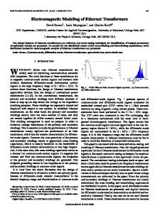
Analyzing (11) and (12), we conclude that only in the case for which φ = 0 (the transformer ratio becomes a:1) there is an equivalent π circuit for this general model. Numerical Example: Consider a three-phase transformer with nominal values of 1,000 MVA; 13.8 kV ∆/345 kV Y, X eq = 5%. The low voltage windings (LV) have taps with variation of ±10%. Let the tap be selected to reduce the high voltage (HV) by 10%. Thus, according to
52
If a load represented by an impedance of 0.4 + j0.4 pu(Ω) is connected on the HV side, the results are slightly different. Now the complex voltages on the HV winding are 0.8456⬔-3.37° pu and 0.8556⬔-2.76° pu for the models represented by (6) and (10), respectively. Considering each LTC transformer individually we find that the difference between the models does not seem to have a major effect on the numerical results. The reason for this is that the tap range is small (generally from 0.9 to 1.1). In a large power system, the number of LTC transformers can be large enough so that different levels of voltage magnitude are determined. In this case, the losses and the total values of generated powers corresponding to the different models are significant. We tested a stressed real system with 749 buses and 260 LTC transformers. Using the model based on (10) without adjusting the transformer admittance, a solution was found using Newton’s power flow after seven iterations. No convergence was obtained when using the correct model of (6), however. These results lead to the following question: Is the correct modeling too stringent as to overstress the network? Conclusions: This work points out the transformer model problem in steady-state power system analysis and shows the differences resulting from an incomplete modeling. Different models for transformers with off-nominal turns ratios and their influence on the equivalent π circuit parameters were analyzed. A general model was presented that incorporates both LTC and phase-shifting effects. We note that, if the impedance value is adequately considered when the transformer is represented, the models discussed in this work provide the same results in terms of complex voltages and currents. Otherwise, the models may lead to different results. References: [1] G.W. Stagg and A.H. El-Abiad, Computer Methods in Power System Analysis. Tokyo: McGraw-Hill, 1968. [2] O.I. Elgerd, Electric Energy Systems Theory: An Introduction. New York: McGraw-Hill, 1971. [3] C.A. Gross, Power System Analysis. New York: Wiley, 1979. [4] J.D. Glover and M. Sarma, Power System Analysis and Design. Boston: PWS-Kent, 1987. Copyright Statement: ISSN 0282-1724/01/$10.00 2001 IEEE. Manuscript received 25 July 2000. This paper is published herein in its entirety.
The PES Web site (http://www.ieee.org/power) contains current information on PES Meetings, Chapters, and Technical Activities. The home page contains links to the following items to which we call your attention: ● PES 2001 Organization Manual & Committee Directory (soon to be available) ● PES Author’s Kit and Presentation Guidelines.
IEEE Power Engineering Review, February 2001