Feb 13, 1995 - generate a perspective view of Walnut Gulch experimental watershed near Tombstone, Arizona; the amplitude at each point in the image is ...
Mapping the World's Topography Using Radar Interferometry: the TOPSAT Mission Howard A. Zebker, Thomas G. Farr, and Ronald P. Salazar Jet Propulsion Laboratory California Institute of Technology 4800 Oak Grove Drive Pasadena, CA 91109 Timothy H. Dixon Rosenstiel School of Marine and Atmospheric Science University of Miami Miami, Florida 33149-1098 Revised: February 13, 1995 Submitted to: IEEE Proceedings Special Issue
Please address correspondence to: Howard A. Zebker MS 300-227 Jet Propulsion Laboratory 4800 Oak Grove Drive Pasadena, CA 91109 Tel. (818) 354-8780, FAX (818) 393-5285
1
2
Abstract Global-scale topographic data are of fundamental importance to many Earth science studies, and obtaining these data are a priority for the Earth science community. Several groups have considered the requirements for such a data set, and a consensus assessment is that many critical studies would be enabled by the availability of a digital global topographic model with accuracies of 2 m and 30 m in the vertical and horizontal directions, respectively. Radar interferometric techniques have been used to produce digital elevation models at these accuracies and are technologically feasible as the centerpiece of a spaceborne satellite mission designed to map the world's land masses, which we denote TOPSAT. A radar interferometer is formed by combining the radar echoes received at a pair of antennas displaced across-track, and specialized data processing results in the elevation data. Two alternative implementations, one using a 2 cm-� radar, and one using a 24 cm-� radar, are technologically feasible. The former requires an interferometer baseline length of about 15 m to achieve the required accuracy, and thus could be built on a single spacecraft with a long extendable boom. The latter necessitates a km-long baseline, and would thus be best implemented using two spacecraft ying in formation. Measurement errors are dominated by phase noise, due largely to signal to noise ratio considerations, and attitude errors in determining the baseline orientation. For the 2 m accuracy required by TOPSAT, the orientation must be known to 1 arc-second. For the single spacecraft approach, where attitude would be determined by star tracking systems, this performance is just beyond the several arc-second range of existing instruments. For the dual spacecraft systems, though, di�erential global positioning satellite measurements possess su�cient accuracy. Studies indicate that similar performance can be realized with either system.
Introduction An accurate description of the surface elevation of the Earth is of fundamental importance to many branches of Earth science, as has been detailed in the reports of several working groups [1-4]. These studies have considered the characteristics of the available topographic data base as well as existing and possible new scienti c applications of high-resolution topographic data. Key ndings of these groups are that there are signi cant de ciencies in available topographic data, that existing and potential new scienti c applications are severely limited by these de ciencies, and that ready availability of a worldwide digital elevation model is a priority for these studies. The required characteristics of the data set are that: i) the data cover the majority of the Earth's land surface, ii) all data be expressed in a common coordinate system, iii) the data exhibit uniform accuracy, and iv) the vertical accuracy and spatial resolution of the model be approximately 2 m and 30 m, respectively. The development of interferometric radar systems for the measurement of highly accurate digital elevation models (DEMs) has by now been well-documented in the literature [5-12]. The precision of the technique is now commensurate with conventional optical-stereo photogrammetric procedures [13], while data reduction time is a small fraction of that required by the optical-stereo instrument
3 systems, which follows mainly from the automated nature of the radar data processing. In addition, because the radar signals easily penetrate even dense clouds in the atmosphere and are independent of solar illumination, there are also far fewer restrictions on data acquisition times and geometries from either airborne or spaceborne platforms. Therefore, it is feasible to design a space mission dedicated to the acquisition of a global digital topographic data base at accuracies superior to existing elevation models, including those described only in paper contour map format. In fact NASA has been studying such a mission for several years to support many ongoing research programs and the general science community. Consideration of accuracy, facility of data reduction, and cost has led to the selection of the interferometric radar technique as the leading candidate for this mission, which we denote TOPSAT. The principal TOPSAT goal is to map the topography of the entire Earth in less than a year at an accuracy similar to that exhibited by 1:50000 maps. In this paper we review the scienti c need for global digital topographic data, including the requirements for the data set and a brief comparison of some data acquisition techniques. We then give a brief tutorial on the radar interferometric technique as applied to topographic mapping. This is followed by examples of the performance and application of such a system using data generated by TOPSAR, an airborne prototype of the space instrument, and also by repeat track analysis of data acquired by the ERS-1 radar satellite. Next, we present two possible designs of a spaceborne topographic radar system, one in which the interferometer is formed by using two antennas on a single spacecraft and one in which two platforms orbiting in formation are utilized. Finally, we present conceptual designs of the complete spacecraft systems needed to realize the TOPSAT mission.
Science Rationale
Digital topographic data are valuable among a wide community using maps on di�erent scales for a variety of political, social, and scienti c applications. In this section we will discuss quanti able scienti c studies enabled by large scale, high resolution elevation data. We then will present summaries of required accuracies for several discipline investigations. Finally, we will discuss several technologies used for generation of topographic data and show why the radar interferometric technique is the leading candidate for a spaceborne topographic mission. Among the studies requiring continental topographic data are hydrology, ecology, glaciology, geomorphology, and atmospheric circulation. For example, in hydrologic and terrestrial ecosystem studies, topography exerts signi cant control on intercepted solar radiation, water runo� and subsurface water inventory, microclimate, vegetation type and distribution, soil development, and a host of additional interdependent parameters. The topography of the polar ice caps and mountain glaciers is important because it directly re ects ice- ow dynamics and is closely linked to global climate and sea-level change. Monitoring the amplitude of seasonal advance and retreat of mountain glaciers on a global basis and longer term trends of the polar ice sheets can give important
4 information on the rate of global warming. Accurate mapping of the forms and slopes of young geomorphic features such as glacial moraines and feature o�sets and scarps due to recent geological faulting can provide new information not only on the formative tectonic processes but also on the climatic and paleoclimatic processes contributing to their present form. Finally, models of the present and past general circulation of the atmosphere require topography as a fundamental input. NASA has sponsored two working groups, entitled the Topographic Science Working Group [3] and the Joint Topographic Science Working Group, to review previous panel reports and recommend a strategy for generating high resolution, accurate digital elevation measurements of the entire land and ice surface of the Earth in a single consistent reference frame. The Joint Topographic Working Group, in particular, addressed horizontal and vertical resolution requirements for various disciplines. The working group report is still unpublished in its entirety, but we present a summary of their ndings in Figure 1 (private notes, authors Dixon and Zebker, who were participants in the group). This gure emphasizes the wide range (over several orders of magnitude) of requirements. Nevertheless, some common features stand out. First, several disciplines require very high resolution topographic data with horizontal resolution of a few tens of meters (approximately the resolution of current high resolution space-based imaging systems such as Landsat TM and SPOT) and vertical precision of several meters or better. Acquisition of high horizontal resolution data with high vertical accuracy automatically satis es all other lower resolution and accuracy requirements and thus is highly desirable. Vertical accuracy should not be signi cantly worse than vertical precision (we de ne the latter informally as the relative height uncertainty for adjacent pixels) to facilitate regional comparisons and comparisons of data taken at di�erent times. High vertical precision (a few 10's of cm) over the polar ice sheets is particularly important to enable mass balance studies. Here, high horizontal resolution is less critical because slopes are generally lower, so widely separated measurements or averages over a few hundred meters do not, in general, cause large height biases. Second, while high resolution data is generally required only in speci c regions, these regions may be located anywhere on the globe, and hence the data should be obtainable anywhere. This is virtually the same thing as a global requirement and demonstrates the desirability of space-based acquisition. However, if sensor power requirements, data-rate or ground processing time become signi cant cost drivers in a space-based mission, a compromise strategy for data acquisition and processing could be adopted whereby data are acquired or processed in high-priority regions rst, building up a global data set more slowly. This approach must be traded o� with the need in some applications to acquire a near-synoptic data set (see below). The third requirement is in the area of multitemporal coverage for change detection and the related issues of synoptic coverage and accuracy. These are most critical for applications involving ice change and vegetation monitoring. While tree heights change slowly and are not usually the subject of topographic maps, the availability of temporally-varying global height maps would permit global change studies such as forest destruction and regrowth. These ecological studies are not
5 supported well by traditional mapping activities, but represent some of the new possibilities enabled by rapid global mapping technology. It is thus desirable to acquire data relatively quickly, ideally over a 1-2 year period or less, as opposed to building up a data base more slowly, for example over a 5-10 year period as might be feasible with stereo-optical systems. It is feasible to acquire "nearsynoptic" global data in 6 months with a radar interferometer. Seasonal or other shorter period e�ects will still have to be accounted for by modeling or other measurement. Obviously if a global set could be acquired in 6 months, and the mission continued for 3 years, changes over this period could be detected. Even if data acquisition ended after one year, future missions would bene t from a near-synoptic data base for comparison purposes, assuming su�cient accuracy. The ability to compare with future data sets may be the most important constraint on the resolution and accuracy requirements of a topographic mission, as we cannot predict all possible future applications of a global, ne resolution, high accuracy data set. Examination of the gure above shows that many of the investigations would be enabled if elevation data at a vertical accuracy of 2-5 m and a spatial resolution of 30 m were available, requirements satis ed by the technological considerations discussed below. The principle exceptions here are the polar ice studies, which do not require ne spatial resolution but do need very precise (10 cm scale) vertical accuracies for adequate calculation of ice volumes. These values, along with coverage needs, form the mission requirements. The existing inventory of topographic data has been produced from a variety of regional and local data sets representing a potpourri of horizontal and vertical datums, accuracies, styles, map projections, and resolutions making it nearly impossible to produce a uniform data set or assess the accuracy of the resulting derived product. The best existing digital data base is the Digital Topographic Elevation Data (DTED) produced by the United States Defense Mapping Agency. DTED have been produced for about 70% of the Earth's land surface, mostly in the northern hemisphere. Completion of a global data set, exclusive of the Greenland and Antarctic ice sheets, is anticipated by 2005. Current production of DTED is accomplished by automated photogrammetry using classi ed orbital stereoscopic images. Previously, DTED were produced by traditional analog photogrammetry and by digitization from contour maps. DTED, although not classi ed, are limited in distribution to members of the Department of Defense and their contractors. This distribution policy is currently under review. The quality characteristics of DTED, taken from public-domain DMA product speci cations for photogrammetrically derived data, are about 90 m spatial resolution and tens of meters accuracy in the vertical direction. A comparison of data requirements versus measurement performance demonstrates that DTED quality does not meet the needs of most scienti c disciplines. The relatively coarse DTED horizontal grid size is insu�cient for disciplines requiring local digital topographic data. Even with spatial averaging, the poor vertical accuracy of DTED, which is due mostly to large systematic errors, also precludes its suitability for most regional and global scienti c disciplines.
6 There are at least three possible technologies for generation of future topographic data on a global scale, i) optical-stereo instrumentation, ii) laser pro ling instruments, and iii) radar interferometry. Of these, the optical-stereo approach has the advantage that it utilizes existing or planned satellite systems justi ed by a broad spectrum of applications. Currently these include SPOT (Systeme Probatoire d'Observation de la Terre), JERS-1 (Japanese Earth Resources Satellite) OPS (Optical System), AVNIR (Advanced Visible and Near-Infrared Radiometer) on the Japanese ADEOS (Advanced Earth Observing System), HRMSI (High Resolution Multispectral Stereo Imager) on Landsat 7, and ASTER (Advanced Spaceborne Thermal Emission and Re ection) on EOS. Depending on the exact system involved, spatial resolutions ranging from 20-40 m and vertical accuracies of 10-60 m may be achieved [14,15]. It is important to note that these accuracies cannot be achieved without suitable ground control point knowledge, clearly an undesirable need for a global system. In addition, truly global coverage is unlikely, even with a space mission, due to orbital limitations and the requirement for two cloud-free scenes with compatible imaging geometry. For these reasons, stereo-optical data would likely be acquired in a piecemeal fashion, slowly building up coverage from a variety of missions with di�erent orbits, illumination conditions, and accuracies. Thus, space-based stereo-optical data would su�er from one of the most vexing problems with existing digital topographic data bases, namely the lack of consistency. Perhaps the major constraint on any stereo-optical approach is the existence of clouds in the Earth's atmosphere. Many areas of the globe are cloud-covered much of the time (especially high-relief or tropical areas) and have never been photographed from space. This is not to say that such areas are cloud-covered all of the time. However, any sun-synchronous orbital platform is constrained to y near local noon (�2 hours), in order to minimize shadows and to ensure adequate solar illumination for passive optical sensors. Especially in tropical areas, cumulus clouds formed by solar heating of the ground and resultant convection generally start to form by mid-morning, severely limiting optical detection from sun-synchronous orbital platforms in certain locations. The second approach is that of laser pro ling, where one or more laser beams illuminate the Earth in a near-nadir direction to collect data directly beneath the satellite ground track. This approach has the advantage of very high vertical accuracy (� 0.1 - 1 m), but the disadvantage that for practical implementations only a very narrow swath may be acquired at one time. For example, if a thirty beam laser were employed with each beam separated by 30 m, the swath would be less than one km and complete orbital coverage, with overlaps, would take over 4 years, stressing the performnace in terms of lifetime and e�ciency of laser transmitters. It also requires that the orbit be controlled to about 50 m, a challenge in itself. Finally, although only a single pass is required over each region of the Earth's surface, the same atmospheric limitations noted for the stereo imaging a�ect laser performance. We note here that there are certain studies, such as the polar ice volume measurements, for
7 which the laser altimeter's high vertical precision and low spatial coverage are ideal, and an overall global topographic study would bene t from the inclusion of a laser instrument to permit the polar study. The nal approach, radar interferometry, achieves the required resolutions and accuracies in a reasonable mission lifetime without interference from clouds in the atmosphere. If a very short radar wavelength is employed, there remains the possibility of interference from severe storms, which, fortunately, are much more rare than clouds in the sky. We describe this approach in detail in the next section, concluding that interferometric radar promises the highest quality product in the shortest time. The remaining discriminator is of course cost, and implementation studies are now investigating the cost issue in detail. For the remainder of this paper, we will assume that there is no signi cant cost advantage in selecting one of the optical approaches and will discuss only the radar implementation.
Radar Interferometry A radar interferometer is formed by relating the signals from two spatially separated antennas; the separation of the two antennas is called the baseline. Radar interferometers have been realized in two ways. First, the two antennas may be mounted on a single platform. This is the usual implementation for aircraft systems [5,6,9], having the advantage of simultaneous observation (see below) but su�ering from the disadvantage that the size of the airframe limits the achievable baseline. However, choosing a high operating frequency permits the baseline, measured in wavelengths, to be of su�cient length for meter-scale vertical accuracies. Second, synthetic interferometers have been formed by utilizing a single antenna on a satellite in a nearly exact-repeating orbit{ the interferometer baseline is formed by relating radar signals on passes over the same site [7,8,12]. Even though the antennas do not illuminate the same area at the same time, if the ground is completely undisturbed between viewings the signals will be highly correlated and a spatial baseline may be synthesized. Here the choice of a baseline is limited only by orbit navigation accuracy, but the surface decorrelation properties must be considered. Topographic maps using this technique have been demonstrated [7,16-18]. A third implementation, proposed for one possible implementation of the global spaceborne mission, is to utilize two spacecraft ying in tandem orbit. This has the advantage of obtaining arbitrary baselines while avoiding the temporal decorrelation phenomenon. The performance of the radar interferometer depends on the radar instrument parameters, the orbit or aircraft attitude parameters, and the errors induced by the data processing and post processing operations. For the repeat-pass implementation only, temporal decorrelation constitutes an important and in many cases the limiting error source in the operation of a topographic mapping radar. Zebker and Villasenor [18] investigated temporal decorrelation phenomena for the SEASAT 24 cm-� (L-band) radar and were able to determine rates of decorrelation for several types of surfaces. A similar analysis of ERS-1 6 cm-� (C-band) data [12] found that the decorrelation rates are often so much higher, and unpredictable, that the utility of the topographic maps derived
8 from the radar measurements is limited. Therefore, the repeat pass implementation is a much less desirable candidate for global studies where complete coverage at uniform accuracy is required, and we will not consider it further here. The theory of topographic mapping using radar interferometry has already been presented in some detail [6,19,20]{ here we summarize the main results and establish notation. We note that for repeat pass imaging geometries, on each pass the radar acts as both a transmitter and receiver, therefore the path di�erence from each to a given point on the surface is twice what would be expected if a single spacecraft or aircraft with two physical antennas is used. Thus, some of the equations listed here di�er from those in the references by a factor of two. Given two antennas A1 and A2 as shown in gure 2, surface topography z(y), the spacecraft altitude, h, above a tangent plane at the point of interest, the baseline distance, B, the range to a point on the ground, r, the look angle, �, and the angle of the baseline with respect to horizontal, �, a radar signal transmitted from antenna A1 and received at both A1 and A2 will form an interferogram where the phase at each point is equal to the di�erence in path lengths �. The measured phase of the interferometer is directly proportional to this distance, with the constant of proportionality 2�� . Using the law of cosines we can determine the following equations for height as a function of these parameters: �=
�� 4�
(1)
2 ? r2 ? B 2 sin(� ? �) = (r + �) 2rB
(2)
z (y) = h ? r cos �
(3)
where � is the measured phase, and � is the wavelength. The above constitute a recipe for measuring topography with the interferometer. The two principal errors associated with the measurements arise from uncertainties in the measured phase and in the knowledge of baseline attitude. First, di�erentiation of (1-3) with respect to � yields the error in height estimate as a function of the error in phase estimate: �z =
�r 4�B tan � ��
(4)
where �z and ��are the standard deviations of height and phase, respectively. The second signi cant error source results from inaccuracies in knowledge of the interferometer baseline alignment. That is, it is impossible to distinguish a baseline angle knowledge error from a slope on the surface topography, and therefore extremely precise knowledge of the baseline geometry is required if absolute height estimation is needed. Again, di�erentiation but with respect to � yields �z = r sin ���
(5)
9 Note that the error is independent of baseline length and depends only on attitude and range. This is a stringent constraint for spaceborne geometries where the range from the radar to the image swath can be many hundreds of kilometers. For TOPSAT's goal of 2 m accuracy the baseline orientation must be known to about 1 second of arc. We note that this requirement is for absolute accuracy only { relative height measurements corrected with ground control points to determine the absolute values do not require this accuracy. However, the additional costs associated with acquiring and integrating a worldwide ground control point data set probably outweigh the cost of the spacecraft systems needed to achieve arc second pointing knowledge. Phase noise (eq. 4) in interferometric radar signals arises from several sources, including thermal noise, sampling and processing artifacts, and statistical correlation of the individual radar echoes before there are combined to form the interferogram. Thermal noise is of course minimized by using the greatest possible transmitter power and lowest noise receivers. Sampling and processing artifacts are a tradeo� between data system complexity and cost. All of these factors are well known in radar system design. However, for interferometric systems, the correlation property of the echoes represent a new factor limiting performance. Decorrelation noise arises mainly from three sources, rotational, temporal, and baseline e�ects [18]. Rotation of the viewing angle between passes is important particularly when interferometric techniques are applied to satellites in crossing orbits [17], but these systems would never be practical for global mapping applications, and we will ignore this term here. Temporal decorrelation is important when the two radar echoes are not acquired simultaneously, as in the repeat pass technique, but as TOPSAT will likely be implemented using contemporaneous observations we can ignore that e�ect as well. Baseline decorrelation results from viewing the surface at two slightly di�erent angles and increases with increasing angle (or baseline). The correlation between echoes varies approximately linearly, decreasing from unity at zero baseline to zero at a critical baseline Bc =
�r
2Ry cos2 �
(7)
where Ry is the ground range resolution and a nearly horizontal baseline, appropriate for orbital implementations, is assumed [18]. Thus a tradeo� is involved in any interferometer design{ the baseline must be large enough to give su�cient phase sensitivity to height (eqs. 1-3) yet small enough as not to introduce too much decorrelation noise. The baseline length may be optimized by expressing the uncertainty in phase ��as a function of thermal signal to noise ratio, processing parameters, and baseline parameters, as [19]: ��=
p
1? p
2N
2
L
(8)
10 where NL is the number of radar \looks,"
=
1 ? BBc 1 1 + SNR
(9)
and SNR is the thermal signal to noise ratio. It is worth noting that an active area of research in interferometric techniques involves the minimizing of baseline decorrelation at the expense of a loss of range resolution [8]. While in theory this is valid for at surfaces, practical problems appear to limit its usefulness for practical systems. However, should the studies indicate that alternative processing could eliminate a major noise source, it would certainly be included in the data system design.
Existing Radar Systems and Data Examples In this section we illustrate interferometric radar principles by presenting data acquired by the TOPSAR airborne prototype topographic radar and by the ERS-1 radar satellite operating in a repeat pass mode. While TOPSAT would not be implemented by an ERS-1 repeat pass approach, the large areal coverage and global availability permitted by spacecraft systems is hard to appreciate by examining only aircraft strip maps, thus we include an example here. The TOPSAR interferometric synthetic aperture radar system is implemented on the NASA DC8 aircraft, where NASA /JPL also operates a multifrequency (P, L, and C bands), multipolarimetric radar (AIRSAR). The TOPSAR implementation uses much of the existing AIRSAR hardware. When in use, TOPSAR e�ectively replaces the C-band polarimeter instrument, but the remaining Land P-band systems are undisturbed and operate together with the topographic mapper, producing simultaneous L- and P-band fully polarimetric, plus C-band VV polarization backscatter images in addition to the topographic product. There are considerations speci c to the TOPSAR environment which led to the existing design (tables 1 and 2 below). The DC-8 airframe fuselage can support only a 2 to 3 meter baseline without requiring signi cant modi cations and this limits performance. The intrinsic range resolution of the AIRSAR is 3.75 m, thus the critical baseline at C-band from equation (7) is 150 m. The optimal baseline, balancing height sensitivity in the phase measurements and processing feasibility, is about one tenth to one fth of the critical baseline, or about 15-30 m. Clearly the airframe will not support an interferometer at the optimum baseline and we must settle for the largest baseline attainable. We therefore chose to mount one antenna below the existing P-band antenna fairing and the second at window level, yielding a 2.58 m baseline. Although this is a factor of ten less than optimum, reasonable performance is achieved. The ERS-1 satellite contains several instruments, including the synthetic aperture radar. Since only one antenna is used on the spacecraft, we must rely here on repeat pass analysis to form the interferometer. This radar also operates at C-band and has somewhat lower performance in terms
11 of signal to noise ratio and resolution as compared to the aircraft system. However, the swath width is over 100 km in contrast to the 10 km swath imaged by TOPSAR.
The main factors a�ecting topographic mapping performance for the ERS-1 repeat pass case are baseline length, baseline alignment, and temporal decorrelation of the surface. For ERS-1 the critical baseline from (7) is 1100 m, and best performance is realized for a baseline length near 200 m. ERS-1 has been operating in a 35 day repeat cycle for nearly two years and fortunately many revisits to a site have been possible. Derivation of a DEM requires selecting a pair from the set of available data with a usable baseline. The knowledge of the baseline orientation is about 3 mrad using the best available orbit reconstructions, yielding an absolute height error from (5) of 50 m. This is not useful for global studies, but given a set of ground control points a digital elevation model may be derived.
For a repeat pass implementation, it is important to minimize temporal decorrelation, and areas of the world with little surface change, such as deserts, are the best candidates for application of ERS-1 as a topographic measurement tool. Forests and other vegetated areas as well as areas subject to freezing and thawing will return radar echoes that are less well correlated due to changes during the 35 day revisit interval [12]. Again, since this radar was not designed speci cally for interferometric applications, performance has not been optimized for topographic mapping. However, the application gracefully degrades with suboptimal geometry and under reasonable conditions of orbit alignment and surface temporal properties topographic maps may be derived. Table 1. TOPSAR and ERS-1 radar system parameters
12 Parameter Wavelength, m Peak power, watts Pulse rate, Hz Pulse length, � sec Antenna length, m Antenna width, m Antenna gain, dB Range bandwidth, MHz Receiver noise temperature, K Antenna baseline, m Baseline angle (�), deg Slant range resolution, m Azimuth resolution, m Platform altitude, km Look angle, deg Repeat interval, days
TOPSAR 0.0566 1000 600 nominal 5.0 1.6 0.11 25 40 2100 2.58 62.77 3.75 1.2 8 20-65 N/A
ERS-1 0.0566 4800 1679 nominal 37.1 10 1 43.2 15.55 3700 Variable Variable 9.6 6.5 790 23 3, 35, 165
We can estimate the system signal to noise ratio for each with the aid of a design control table (Table 2). Given the TOPSAR baseline parameters, assuming a nominal 200 m baseline length and horizontal alignment for ERS-1, and the signal to noise ratios we can then analyze performance of the interferometers. Equation (9) yields a phase noise of 2.8�and 9.1�, respectively, for the TOPSAR and ERS-1 systems; equation 4 then gives height uncertainties of 1.4 and 2.4 m, respectively.
13 Table 2. Design control tables Parameter Peak power Antenna directional gain Antenna e�ciency 1 4� 1 R2
Illuminated area �0
1 4� 1 R2
Antenna area Antenna e�ciency System losses Oversampling gain Total Thermal noise (kTB) Signal to noise ratio
TOPSAR (dB/dBW)
ERS-1 (dB/dBW) 30 28 -5 -11 -80 53 -15 -11 -80 -8 -5 -8 5
36.8 45.9 -3 -11 -118.6 78.4 -15 -11 -118.6 10 -3 -3 1.8
-106 -119
-110.3 -120.0
13
9.7
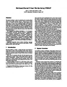
Figure 3 illustrates a sample DEM acquired by TOPSAR. Here the elevation data are used to generate a perspective view of Walnut Gulch experimental watershed near Tombstone, Arizona; the amplitude at each point in the image is determined by the radar backscatter coe�cient. Since the amplitude and the phase information are carried together in the data processor, precise alignment of the radar brightness and terrain information is maintained. This makes it relatively easy to reference the location of points in the DEM to a known coordinate system as many features are identi able in the radar backscatter image. Figure 4a is a TOPSAR image acquired over Ft. Irwin, near Barstow, CA. This was the site of a veri cation experiment [13] where TOPSAR data were compared with a very accurate DEM produced by the U.S. Army Topographic Engineering Center (TEC). The stated 1 m or better accuracy of the TEC reference DEM (shown in shaded relief representation in gure 4b) was ensured by using many ground control points. In gure 4c we plot an error map of the height di�erence between the TEC DEM and that obtained by TOPSAR. Peak errors approach 10 m, but for rms error the agreement is to the 1 m level in the at regions and 2-3 m in the mountainous regions, as expected by the theoretical models.
14 TOPSAR shows its usefulness by acquiring data over regions of scienti c interest for which the existing data are poor or nonexistant. One such region is the Galapagos Islands, which are remote and di�cult to measure by conventional means, however are of great interest to the volcanology community. It is expensive to deploy aircraft with stereo cameras for extended lengths of time, which would be required to obtain complete cloud-free coverage over the entire islands. TOPSAR covered several interesting islands in a matter of a few hours. In gure 5 we show a contour map derived from TOPSAR data over the Galapagos island of Fernandina. In this case there are no known elevation data of large parts of the island and for those data that exist the accuracy is not well characterized. This map is now the best available, and is in convenient digital format. It consists of four strips mosaicked into a single image and covers an area of about 900 km2. As mentioned above, the principle advantages of spaceborne platforms are large areal coverage and global data acquisition. We have selected an interferometric pair of scenes acquired over part of the Mojave Desert in California, where little temporal decorrelation occurs and we chose two orbits separated by about 100 m in space. From these data we produced the ERS-1 digital elevation model shown in gure 6. This image is 40 km on a side, and represents a subset of a single swath of radar data. While we have not completed a detailed performance analysis of this scene, analyses on similar scenes [12] indicates that 5 m vertical precision at 40 m spatial resolution may be achieved if 5 ground control points are identi ed within the image and used to constrain the solution.
TOPSAT Implementation Options
In this section we present two possible spacecraft implementations that could satisfy many of the global topographic mapping requirements as described above. Each approach has its own limitations based on available technology. Thus, many of the limits to performance described here result from details of the implementation rather than by shortcomings of the technique. However, both of the proposed implementations are feasible and are an appropriate starting point for a realistic system design. If we eliminate repeat pass implementations as unreliable for a global mapping mission requiring contiguous, uniform data over much of the Earth, two alternatives for interferometric radar instrument designs remain: i) a single spacecraft with two displaced antennas, and ii) two spacecraft, each with a synthetic aperture radar, ying in formation to form the interferometer baseline. For each system, the basic limitations to interferometer performance as decsribed above remain. Signal to noise ratio must be maximized in the constrained spacecraft environment, the baseline must be of su�cient length to give the desired height sensitivity without causing too much baseline decorrelation, and the baseline attitude must be measured at the 1 arc second level. The requirement to realize su�cient signal to noise ratio, coupled with technological limitations on transmitter e�ciencies, practical device power ratings, and spacecraft prime power levels, translates into a need for a large antenna compared to the wavelength, producing a relatively narrow swath. The single spacecraft design we present here (tables 3 and 4) produces a 10.5 km swath
15 after accounting for overlap in the mosaic process, and thus requires at least 241 days to map the world completely. A longer mapping cycle is more costly for two reasons: the design lifetime of the spacecraft must be longer and the operations phase of the mission lasts longer. The single spacecraft approach would achieve the required baseline lengths by mounting one or both of the antennas on a boom at a distance from the spacecraft. A boom would likely be limited to about 25 m length (see next section), therefore to form an adequate baseline the wavelength would have to be short, preferably 2 cm (Ku-band) or less. The e�ective boom length, however, can be doubled by \ping-ponging," or alternately transmitting from each antenna, at a cost of cutting pulse repetition rate and the average power per channel by a factor of two, which also increases azimuth ambiguities due to undersampling of the Doppler spectrum. Baseline attitude determination would be achieved by measuring both the rigid body spacecraft attitude and the structural distortion between the two antennas. The spacecraft attitude can be measured by a star tracking system and the structural distortion by a laser metrology system. Of these two the measurement of spacecraft attitude to less than one arc-sec is the more di�cult. Current star trackers cannot measure absolute attitude to less than several arc-seconds, due to limitations in the trackers themselves, uncertainties in mechanical spacecraft exure, and by limitations in absolute knowledge of star positions (private communication, S.J. Wang, JPL internal memorandum Jan. 10, 1994). Several of the above limitations could be reduced by using two spacecraft to form the interferometer by ying in proper formation. Since the baseline can be much longer, a twin spacecraft approach could utilize a much lower frequency, and hence technologically simpler, radar system (see tables 3 and 4). We have chosen L-band with a wavelength of 24 cm as a nominal approach due to the relative technological maturity of the radar electronics{ SEASAT, SIR-A, SIR-B, SIR-C, and the Japanese JERS-1 satellites all have L-band radar channels. Here we would navigate the two spacecraft in \parallel" orbits, identical except in node crossing, to form any desired baseline length. The baseline attitude knowledge requirement is still at the 1 arc-second level, but di�erential Global Positioning Satellite (GPS) techniques promise to determine the relative positions of the spacecraft to a precision of about 3 mm in all directions [21]. If the baseline length is nominally 1000 m, this translates to 0.62 second of arc, well within the requirements. Successful measurement of the relative position of the interferometric antennas to an accuracy of 3 mm relies on extrapolation of current GPS system performance using knowledge of error sources gained from the TOPEX GPS precision orbir determination experiment. This experiment resulted in absolute position knowledge to the several cm level [22]. The total error was found to have four main sources: i) receiver thermal noise, ii) multipath e�ects, iii) satellite orbit knowledge limitations, and iv) ionospheric propagation e�ects. Since TOPSAT will require only the relative spacecraft positions at the very high precision, and since the spacecraft are identical in con guration and separated by only 1-2 km, the contributions of the last three error sources are reduced from
16 the cm level to the mm level. In the twin spacecraft case, navigational complexity associated with two spacecraft orbiting within 1 km of each other, not to mention the additional cost of a second spacecraft, are the principal challenges. Spacecraft to spacecraft communications and synchronization are required and the data downlink problem may be more di�cult. All of these problems can be solved with existing technologies, and the ultimate arbiter in the choice between one and two spacecraft will likely be the cost issue.
17 Table 3. TOPSAT Ku- and L-band radar system parameters Parameter Wavelength, m Peak power, watts Pulse rate, Hz Pulse length, � sec Antenna length, m Antenna width, m Antenna gain, dB Range bandwidth, MHz Receiver noise temperature, K Antenna baseline, m Baseline angle (�), deg Slant range resolution, m Azimuth resolution, m Orbit altitude, km Look angle, deg Orbit repeat interval, days
Ku-band 0.02 750 3800 60 5 0.65 49.9 20 700 25 30 7.5 3.3 440 30 241
L-band 0.24 1600 2100 50 9 3.5 38.4 20 600 800-2000 (variable) 0 7.5 5.9 564 30 84
18 Table 4. TOPSAT design control tables Parameter Peak power Antenna directional gain Antenna e�ciency
Ku-band (dB/dBW)
L-band (dB/dBW)
Antenna area Antenna e�ciency System losses Oversampling gain
28.8 49.9 -3 -11 -114.1 75.8 -13 -11 -114.1 5.3 -3 -3 2.1
32.0 38.4 -3 -11 -116.3 84.2 -20 -11 -116.3 15 -3 -3 2.1
Total Thermal noise (kTB)
-110.3 -125.2
-111.9 -126.9
Signal to noise ratio
14.8
15.0
1 4� 1 R2
Illuminated area �0
1 4� 1 R2
A complete error budget [19] for both implementations is shown in table 5. Here we break down the total error into many components, only two of which (denoted height phase noise error and height attitude error) were described previously (equations 4 and 5). Details of this procedure are beyond the scope of this paper, please consult the reference for more information.
19 Table 5. TOPSAT error budgets (all values in meters) Parameter
Ku-band L-band Flat terrain Sloped terrain Flat terrain Sloped terrain
Height errors, m Phase noise error Baseline error Attitude error Orbit height error Other
3.26 0.00 1.23 0.10 0.10
5.32 0.00 2.01 0.10 0.16
1.94 0.71 0.98 0.10 0.10
3.17 1.15 1.59 0.10 0.16
RSS total
3.48
5.68
2.29
3.73
Across-track position errors, m Phase noise error 5.65 Baseline error 0.00 Attitude error 2.13 Navigation error 3.00 Other 0.10
3.36 1.22 1.69 3.00 0.10
RSS total
4.97
6.74
Along-track position errors, m Orbit timing error 0.01 Navigation error 3.00
0.01 3.00
Orbit Characteristics. Advantages accrue for both concepts if a sun synchronous orbit oper-
ating near the terminator is utilized, as solar illumination remains constant for many months. The main advantages realized by this orbit choice are constant availability of power from the solar panels and few thermal shocks to the spacecraft. The twin satellites operate at an altitude of 565 km and inclination of 97.6 degrees while the single satellite with dual antennas operates at an altitude of 440 km and inclination of 97.6 degrees. The lower altitude is required by the single satellite with dual antennas to maintain adequate height resolution, since the height resolution is a function of antenna spacing and radar signal to noise ratio. Navigation issues for the single satellite implementation are straight-forward and the major concern is to cover the entire Earth with a minimum of gaps. The twin satellite mission design is more complex, involving two spacecraft; it has been described in detail [22] and will be summarized here. For the dual satellite mission, the satellites are injected together into the 565 km orbit. After the correct orbit has been attained, the satellites are separated into two di�erent orbit planes
20 and at slightly di�erent altitudes (a few meters). A good understanding of the satellite's ight properties will rst be determined when the satellites are at a large lag distance. The di�erential drag experienced by the two satellites will be measured, after which the satellites will set at the operational lag distance. After a radar calibration period, the mapping phase will begin. A map of the land masses between � 70�latitude is obtained after about 84 days. By launching at the proper time of the year, two global maps can be obtained before entering solar occultation, the time when Earth shadows disrupt the sun's illumination of the spacecraft solar panels. The baseline mission is de ned as the completion of 60 days of in-orbit checkout followed by two complete 84-day surveys for a total mission duration of approximately 8 months. Both implementations would be planned to conduct dual complete ground surveys. The second survey would ll in any gaps in the rst. Data would be acquired only on the ascending pass in the rst survey because of limitations of on-board storage and downlink data rate. In the second survey, data could be taken on the descending pass also so that the ground would be seen from the opposite look angle. This would help to locate errors in the data that are caused by high surface slope.
Twin Satellite Orbit Con guration. A baseline distance (the distance between the two
satellites measured perpendicular to the velocity vector) of 800 m to 2000 m is required for proper single pass interferometric results. Figure 7 shows that the two orbits are identical except for a 2020 meter di�erence in the locations of the node crossings giving a baseline separation of 2000 meters at the equator and 800 meters at 65�latitude. Because the ground tracks are denser at the higher latitudes, good results can be obtained up to about 70� latitude despite the short relative separation. Coverage between � 70�includes almost all the land areas of topographic interest. By increasing the equatorial separation to 6 km, higher latitudes (about 80 degrees) could be covered in an extended mission.
Data Storage and Downlink. The L-band radar design presented above produces data at a
rate of 51.4 Mb/s per spacecraft, and the Ku-band radar at a rate of 64 Mb/s. This data must be stored on board the spacecraft for transmission to the ground. Ideally the data storage device would have a capacity of 100's of gigabits to provide ground station scheduling exibility and backup for missed passes and on-board failures. It would also be possible to read out any desired random block of data in the same order as it was recorded. Presently no recording device meets the TOPSAT required data rate and volume performance parameters. Although 100 gbit tape recorders are expected to be available in the next few years, they have the disadvantages of moving parts, reverse playback and di�culty in randomly addressing recorded data. Solid state recorders, as are being developed for the EOS-AM platform, would better meet the needs of TOPSAT. Because SARs are such prodigious producers of data, there is almost no point where the amount of storage is considered enough. Any future developments in data storage technology will provide real value to TOPSAT and other future SAR missions.
21 There are two main options possible for data return. One option involves the use of 10 m, X-band ground stations located in Alaska and McMurdo, Antarctica which have frequent opportunities to see the spacecraft as well as additional coverage by 11 m DSN stations. The downlink radar and altimeter data rate would be at 85 Mbits/s. Downlink of GPS and spacecraft engineering data would be at a rate of 512 kbits/s by S-band to either the DSN 26 m network or the McMurdo station. Uplink would be at 2 kbits/s from the DSN 26 m stations. The second data return option would use the TDRSS satellite system in a K-band single access mode and employ high gain antenna on the spacecraft. Even in this case, a large on-board recorder would be needed as TDRSS is run as a facility shared by many users, and is not always available. Normal uplink would also use TDRSS.
Other Mission Issues. The single spacecraft approach relies on precise position and attitude
knowledge and control of two radar antennas separated by a long structure. Occultation-induced thermal changes could disrupt the pointing control as well as causing lower orbit-averaged power availability. The orbit would be designed to minimize occultations but when they occur data collection may be interrupted. When the occultation periods end the spacecraft is orbiting over a di�erent set of ground tracks on the Earth, creating a gore in the map, and data acquisition could not be completed until the unmeasured regions become visible once again. The overall mission could be enhanced, providing additional capabilities to a topographic mission, if a laser pro ling instrument were included in the payload to enable polar ice volume studies. A practical design [24] has a swath width of 150 m and so cannot obtain a complete map except near the poles where the coverage is dense. Away from the poles the laser obtains a contiguous line of points for comparison with the radar data, both for validation and, if necessary, ground control point information. The lines of laser data from successive orbits in this approach are about 32 km apart at the equator. In addition to providing surface height from measurement of the time of ight of the laser pulse, analysis of the return pulse waveform can provide information to help constrain measurements of surface slope, surface roughness, vegetation height and surface re ectance at 1.06 �m.
Flight System Characteristic Summaries. We present here brief descriptions of the complete ight systems as driven by our radar implementation options above. While not strictly descriptive of the radar system itself, it is useful to examine the demand on spacecraft resources from any proposed implementation approach. The major characteristics of both the Ku-band and the L-band system are summarized in table 6. Finally, we show possible spacecraft con gurations for each option in gures 8 and 9. The single satellite launch and on-orbit con gurations are depicted in gure 8. For the case of the twin satellites, both spacecraft can be launched on a single Delta II class vehicle. A possible con guration of the two spacecraft in the Delta shroud and on-orbit is shown in gure 9. In the case of the single spacecraft, the solar array would deploy once and then be xed in
22 position. There would also be a one-time deployment of the outboard antenna boom. The star tracking system would be located on the spacecraft near the radar antenna and a laser metrology system would be used to mesure the position of the second antenna realtive to the spacecraft body. The twin spacecraft implementation also is designed to have a one-time deployment of the radar antenna and solar array. The sun synchronous orbit allows the solar array to be xed in position, decreasing cost and increasing reliability. Table 6. Flight system characteristics Single s/c
Twin s/c
Radar data rate Radar power Radar mass
64 Mb/s 922 W 250 kg
51 Mb/s (each s/c) 694 W (each s/c) 300 kg (each s/c)
Total ight system mass
1460 kg
2315 kg (both s/c)
Launch vehicle capability Launch vehicle margin
3580 2120
3420 kg 1105 kg
Conclusions Global-scale topographic data are of fundamental importance to many Earth science studies, and obtaining these data are a priority for the Earth science community. Several groups have considered the requirements for such a data set, and a consensus assessment is that many critical studies would be enabled by the availability of a digital global topographic model with accuracies of 2 m and 30 m in the vertical and horizontal directions, respectively. The necessity to acquire data globally in a time period of a year or less suggests that active microwave techniques, which are much less susceptible to atmospheric e�ects such as cloud cover than conventional optical techniques, are the preferred technology. Radar interferometric techniques have been used to produce digital elevation models at these accuracies and are technologically feasible as the centerpiece of a spaceborne satellite mission designed to map the world's land masses. A radar interferometer is formed by combining the radar echoes received at a pair of antennas displaced across-track, and specialized data processing results in the elevation data. Two demonstration instruments, the TOPSAR airborne prototype and repeat track analysis of ERS-1 satellite data show that achieving the needed accuracies is feasible at modest cost. The accuracies of the prototype instruments depend mainly on signal to noise ratio of the radar echo and to knowledge of the precise imaging geometry Two alternative implementations, one using a 2 cm-� radar, and one using a 24 cm-� radar, are technologically feasible. The former requires an interferometer baseline length of about 15 m to achieve the required accuracy, and thus could be built on a single spacecraft with a long extendable
23 boom. The latter necessitates a km-long baseline, and would thus be best implemented using two spacecraft ying in formation. Measurement errors are dominated by phase noise, due largely to signal to noise ratio considerations, and attitude errors in determining the baseline orientation. For the 2 m accuracy required by TOPSAT, the orientation must be known to 1 arc-second. For the single spacecraft approach, where attitude would be determined by star tracking systems, this performance is just beyond the several arc-second range of existing instruments. For the dual spacecraft systems, though, di�erential global positioning satellite measurements possess su�cient accuracy. Studies indicate that similar performance can be realized with either satellite system. We have presented here preliminary mission concepts which have the potential to produce a global topographic data set in the near future at modest cost. The realization of a TOPSAT mission requires selection of an implementation approach and its detailed design and construction. There are however, signi cant open issues with respect to end-to-end mission design. Therefore, ongoing work emphasizes re ning the system error budgets and system requirements, de ning the mission implementation approach and technology requirements, as well as examining e�cient methods of ground data processing. None of these are technologically infeasible and it is quite likely that a mature concept can be selected in the near future.
Acknowledgements.
The research described in this paper was carried out by the Jet Propulsion Laboratory, California Institute of Technology, under a contract with the National Aeronautics and Space Administration. Figure captions. Figure 1. Graphical depiction of horizontal and vertical topographic data accuracies required for several discipline studies. Each box represents a range of requirements for di�ering aspects of the studies. Figure 2. Interferometer imaging geometry. Radar antennas A1 and A2 both illuminate the same patch of ground centered at y = 0. Incidence angles �1 and �2 result in phase o�sets for all points P displaced by distance y of y sin �1 and y sin �2, respectively. Di�erence of these phases is measured interferometer phase. Figure 3. TOPSAR Image of Walnut Gulch / Tombstone, Arizona. Perspective from elevation measurements, brightness represents radar backscatter coe�cient. Figure 4. (a) TOPSAR image of Ft. Irwin, CA. This was the site of a veri cation experiment that included a variety of terrains. A conventional stereo photogrammetric image was produced by the US Army Topographic Engiuneering Center (TEC) as a reference. (b) Shaded relief representation of the reference TEC DEM. The TEC map does not cover all ov the area in (a). (c) Error map of the di�erence between the TEC DEM and that from TOPSAR. Although peak errors approach 10 m, in an rms sense the agreement is to the meter level in the at regions and 2-3 m in the mountainous areas.
24
Figure 5. Contour map of Isla Fernandina, Galapagos Islands, derived from TOPSAR DEM. The contour interval is 50 m, and the brightness represents radar backscatter coe�cient. This image consists of four parallel strips mosaicked together. Figure 6. ERS-1 interferometric digital elevation model of part of the Mojave Desert, CA. The bright, at region in the foreground is the Pisgah lava ow, and the dark dry lake in the background is Drinkwater Lake. Figure 7. Dual satellite trajectory for mid latitude and upper latitude coverage. Note that the track separation is greatly exaggerated for clarity - the actual separation of 2 km at the equator would be too small to see at this scale. Figure 8. Single spacecraft con guration in launch vehicle shroud (left), and deployed (right). Figure 9. Twin spacecraft con guration in launch vehicle shroud (left), and deployed (right). References [1] Land Processes DAAC Science Advisory Panel, Topographic data requirements for EOS global change research, In press, NASA Publication, 1993. [2] Task Group on Earth Sciences, Space Science in the Twenty- rst Century: Imperatives for the decades 1995-2015, National Academy Press, 121 pp., 1988. [3] Topographic Science Working Group, Topographic Science Working Group Report to the Land Processes Branch, Earth Science and Applications Division, NASA Headquarters. Lunar and Planetary Institute, Houston, 64 pp., 1988. [4] Committee on Earth Sciences, A Strategy for Earth Sciences from Space in the 1980's, Part 1: Solid Earth and Oceans, National Academy Press, Washington, DC, 99 pp., 1982. [5] Graham, L.C., Synthetic interferometer radar for topographic mapping, Proc. IEEE, vol 62, 763-768, 1974. [6] Zebker, H. and R. Goldstein, Topographic Mapping from Interferometric SAR Observations, Journal of Geophysical Research v.91, No. B5, p. 4993-4999, 1986. [7] Goldstein, R. M., H. A. Zebker and C. Werner. Satellite radar interferometry: two-dimensional phase unwrapping, Radioscience, vol. 23, no. 4, pp 713-720, July-August 1988. [8] Gatelli, F., A. Monti Guarnieri, F. Parizzi, P. Pasquali, C. Prati, and F, Rocca, Use of the spectral shift in SAR interferometry: applications to ERS-1, submitted to IEEE Transactions on Geoscience and Remote Sensing, 1993. [9] Zebker, H.A., S. N. Madsen, J. Martin, K. B. Wheeler, T. Miller, Y. Lou, G. Alberti, S. Vetrella, and
25 A. Cucci, The TOPSAR Interferometric Radar Topographic Mapping Instrument, IEEE Transactions on Geoscience and Remote Sensing, Vol 30, no. 5, pp 933-940, September, 1992. [10] Evans, D.L., T.G. Farr, H.A. Zebker, and P.J. Mouginis-Mark, Radar interferometric studies of the Earth's topography, EOS, Vol. 73, No. 52, pp. 553 and 557-558, December 29,1992. [11] Madsen, S.N., H.A. Zebker, and J. Martin, Topographic mapping using radar interferometry: processing techniques, IEEE Trans. Geosci. Rem. Sensing, Vol. 31, no. 1, pp. 246-256, January, 1993. [12] Zebker, H.A., C.L. Werner, P. Rosen, and S. Hensley, Accuracy of topographic maps derived from ERS-1 radar interferometry, submitted to IEEE Transactions on Geoscience and Remote Sensing, April, 1993. [13] Madsen, S.N., J. Martin, and H.A. Zebker, Analysis and evaluation of the NASA/JPL TOPSAR acrosstrack interferometric SAR system, submitted to IEEE Transactions on Geoscience and Remote Sensing, October, 1993. [14] Muller, J.-P., P. Eales, Global topography accuracy requirements for EOS, Proc. IEEE Geosci. Rem. Sens. Symp., Washington, DC., 1990. [15] Shimada, M., M. Nakai, T. Moriyama, Derivation of topography from OPS stereoscopic data, Proc. CEOS Working Group on Calibration/Validation, Pasadena, CA., 1992. [16] Gabriel, A.K., R.M. Goldstein, and H.A. Zebker, Mapping small elevation changes over large areas: di�erential radar interferometry, J. Geophys. Res. 94, No. B7, pp. 9183-91, July 10, 1989. [17] Gabriel, A. K. and R. M. Goldstein, Crossed orbit interferometry: theory and experimental results from SIR-B, Int'l Journal Remote Sensing, vol 9., no. 8, pp. 857-872, 1988. [18] Zebker, H.A., and J. Villasenor, Decorrelation in interferometric radar echoes, IEEE Transactions on Geoscience and Remote Sensing, Vol 30, no. 5, pp 950-959, September, 1992. [19] Rodriguez, E. and J. Martin, Theory and design of interferometric SARs, Proceedings of the IEE, vol. 139, no. 2, pp. 147-159, 1992. [20] Li, F. and R. M. Goldstein, Studies of multi-baseline spaceborne interferometric synthetic aperture radars, IEEE Trans. Geo. Rem. Sens., vol. 28, no. 1, pp. 88-97, January 1990. [21] Yunck, T. P., private communication and JPL internal memorandum, TOPSAT Orbit Determination and Satellite-Satellite Vector Measurements with GPS, Jet Propulsion Laboratory, 1993. [22] Bertiger, W.I. et al.,GPS Precise Tracking of TOPEX/Poseidon: Results and Implications, submitted to J. Geophys. Res. TOPEX/Poseidon Special Issue, Nov. 1993. [23] Vincent, M. A., Design of the TOPSAT Mission, Presented at AAS/AIAA Astrodynamics Conference, Paper AAS 93-593, August 16-19, 1993. Victoria, B.C., Canada.
26 [24] Bufton, J. L. and D. J. Harding, Multi-Beam Laser Altimeter for the Global Topography Mission, Instrument Description, 1993, Goddard Space Flight Center, Greenbelt, MD, U.S.A.