Abstractâ Memristor as an emerging history dependent nano- meter scaled element will play an important role in future nanoelectronic computing technologies.
Memristor-Based Linear Feedback Shift Register Based on Material Implication Logic Mehri Teimoory*, Amirali Amirsoleimani†, Arash Ahmadi†, Shahpour Alirezaee† Saeideh Salimpour†, Majid Ahmadi† {mehri_teimoory}@yahoo.com {amirsol, aahmadi, alirezae, saeideh, ahmadi}@uwindsor.ca Department of Electrical Engineering, Islamic Azad University, Science and Research Branch, Kermanshah, Iran
*
†
Department of Electrical and Computer Engineering, University of Windsor, Windsor, Ontario, Canada
Abstract— Memristor as an emerging history dependent nanometer scaled element will play an important role in future nanoelectronic computing technologies. Some pure and hybrid memristor-based implementation techniques have been proposed in recent years. Material implication logic is one of the significant areas for memristor-based logic implementation. In this paper a memristor-based linear feedback shift register is implemented based on material implication logic. It is implemented by 8 memristors which is considerably used less area in comparison with conventional CMOS-based peers. Also the proposed memristor-based LFSR circuit needs 55 computational steps for generating a 4-bits number.
design was presented with less computational steps in comparison with previous designs.
Index Terms – Memristor, Linear Feed Back Shift Register, Material Implication, Logic, CMOS, Pseudo Number.
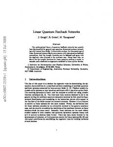
Figure 1: HP’s Pt/TiO2/Pt Memristor structure is shown. The platinum electrodes are the two ends of the Memristor. The TiO2 thin film is divided into two sections with orange and white color. The side with the Oxygen atoms deficiency titanium dioxide (TiO2-x ) and the other side without doping.
Pt TiO2
ROFF
TiO2-x
RON
D x
Pt
I. INTRODUCTION he CMOS technology reaches its limit in scaling based on the Moore’s law. In 2008 in HP laboratory the fourth fundamental element with unique characteristic discovered by scientists [1]. The new emerging memristor promises a good alternative for conventional CMOS technology due to its good scalability, non-volatility, low power and also its compatibility for integration with conventional CMOS structures [2]. By applying a bias voltage over memristor it is behaved like a variable resistor during that time. Also it stores its last resistance as the bias voltage is removed. As it is shown in Fig. 1 memristor is consisted of doped and un-doped regions in insulator layer that is sandwiched by two metallic electrodes. One of the significant application for applying memristor devices is logic implementation. Several memristor-based logic implementation techniques were proposed in literature [3], [4]. Memristor Ratioed Logic (MRL) is a CMOS compatible logic [5]. In this logic the voltage of the output defines the logic states. The other logic family, crossbar array structure, presented in [4] is for performing logic in memory. This family promises integration of memory and logic block in the same unit for future advanced computer architectures. Memristor Aided Logic (MAGIC) [6] and Material Implication Logic (IMPLY) [7] are two main logic proposed for crossbar structures. In these logics unlike MRL logic memristance of the output memristor defines output logical state. In IMPLY logic all logic gates are designed based on IMPLY logic gate. There are few works in memristor-based circuit design based on material implication logic in the literature. In [7] and [8] a memristor-based eight-bit full adders based on material implication logic were designed. Also in [9] the optimized
T
In this paper a 4-bits memristor-based Linear Feed Back Shift Register (LFSR) is implemented based on material implementation logic. LFSR is used in multiple applications like pseudo random number generation, built-in self test, data encryption/decryption and optimized counters in digital circuits. The conventional designed CMOS-based LFSR required at least 30 CMOS transistors while with this technique we have used only 8 memristor devices. Rest of this paper is organized as follows. The memristorbased material implication logic is defined in Section II. The logic implementation with material implication is defined in section III. The proposed 4-bits memristor-based linear feedback shift register designed circuit based on material implication logic is presented with its logic analysis in Section IV. Finally a conclusion and remarks are provided in section V. II. MEMRISTOR-BASED MATERIAL IMPLICATION LOGIC The material implication is a logic that states “if a then b”. This logic is shown by ”a IMP b” which means a implies b. It is also like an answering to a question. a is considered as a question and b is its answer. By considering a as a question when a is false or has logic 0 any answer is considered true then b has logic 1. For the cases that a is true the truthfulness of b is considered the output. Then when b is right the output is considered true or logic 1 and in the case when b is false the output is logic 0. This logic can be written as,
a IMP b a b (~a)˅b
(1)
The truth table of material implication logic is shown in Table. 1. For memristor based material implication logic all basic logics
like AND, NAND, OR and NOR are built based on an IMPLY logic gate. This gate was designed in [7] for implementing a material implication logic with memristor devices. The IMPLY gate is the basic block for circuit design with memristor-based material implication technique. This gate comprises of two memristors (A and B) and one resistor (RG). The IMPLY gate is depicted in Fig. 2. RG resistor is connected the un-doped sides of A and B memristors to the ground. The resistance of RG should be considered between RON and ROFF (RON < RG < ROFF). Also two Vcond and Vset voltages are applied to the doped sides of A and B memristors respectively. The Vcond voltage magnitude is considered lower than Vset (|Vcond| < |Vset|). The main idea for this logic design is using non-volatile characteristic of memristors. The memristance of both A and B memristors are defining the logic value. The RON (low resistance) is considered for logic 0 and ROFF (high resistance) is for logic 1. For setting the memristor to its lowest resistance (RON) forward bias should be applied until the doped region reaches to its maximum length. This procedure is called writing. Also for setting a memristor to its highest resistance (ROFF) it should be inversely biased until the un-doped region covers whole length of the memristor insulator layer. Two Vclear and Vset voltage sources are required for setting A and B memristors to desired logical states. Table.1: Material implication logic truth table Case
a
b
a IMP b
1
0
0
1
2
0
1
1
3
1
0
0
4
1
1
1
In case 1 as it is stated in Table. 1 both memristors should be set to ROFF (logic 0). Therefore A and B memristors are biased with Vclear for enough time. After both memristors are adjusted and set to ROFF, Vcond and Vset are imposed to A and B memristors. Based on voltage division between RG and memristor B a voltage of common node between two memristors becomes negligible. The voltage of memristor B is, R RG RG V B OFF V set Vcond V set (2) ROFF 2 RG ROFF 2 RG Therefore current flows in right branch of IMPLY logic gate from Vset to ground. This makes B memristor’s memristance to be decreased to RON (logic 1) which is the desired output of case 1IMPLY logic truth table. This case is also determined the write time of the circuit. In case 2, A and B should set to ROFF and RON respectively. For this issue Vclear and Vset are applied to the doped sides of A and B memristors respectively. This biasing procedure should last until two memristors reach to their desired memristance values. After that Vcond and Vset are imposed to A and B memristors respectively. Since memristance of B (RON) is too smaller than RG based on voltage division voltage of the common node between two memristors is approximately equal to Vset. The voltage across the memristor B is determined by, R R RG Vset 0 (3) V B 1 ON OFF R R 2 R G OFF ON
2 Therefore there is no voltage across memristor B for changing its state. Memristance of B (RON) remains unchanged
Vcond A
Vset B
A
B
IMPLY Gate
RG A IMP B
Figure 2: Schematic of memristor-based IMPLY logic gate.
and the output will be logic 1. Also case 4 is similar to this case. The voltage across memristor B is determined through, R RG RON V B ON V set Vcond (4) RON 2 RG RON 2 RG Since this voltage is positive the forward bias is applied to memristor B. Although this forward bias force memristor B to decrease its memristance it cannot reach to lower than current memristance (RON). Then the output of the case 4 will be logic 1. In case 3 the memristances of A and B are set to RON and ROFF by connecting to Vset and Vclear respectively. Because of this the voltage across memristor B is, RG V B V set Vcond V set Vcond (5) RON RG This voltage is not enough for changing the memristance of B into RON. The memristance will be decreased to lower values between RON and ROFF but it cannot reach to RON. Therefore the output in this case is logic 0. III. LOGIC IMPLEMENTATION WITH MATERIAL IMPLICATION LOGIC All basic logic gates can be implemented by applying predefined IMPLY logic gate. The main idea for that is by combining IMPLY logic with a FALSE logic. FALSE logic is an IMPLY logic gate with a false answer (logic 0) whether its question is true or false. The simple structure that is shown in Fig. 3 can be used for implementation of all basic logic gates by using memristor-based material implication technique. This structure comprises three A, B and C memristors. A and B are input of the structure while C is output. For example a NAND logic gate can be implemented by, C B IMP ( A IMP C ) ~ B ˅ ((~ A) ˅ C) (5) By setting C to logic 0, C = ~ B ˅ ((~ A) ˅ 0) = (~ B) ˅ (~ A) = ~ (A ˄ B) (6) For implementation of NAND gate FALSE operation should applied to memristor C at first step. For this Vclear is applied to memristor C. Then Vcond and Vset are applied to A and C memristors. After this Vcond and Vset are imposed to B and C. The memristance of C shows logic states as the same as output of a NAND logic gate. In [9] a memristor-based design for XOR logic gate is presented by material implication logic. Unlike [8] design it only uses 9 computational step for its operation. The IMPLY-based implementation of XOR gate is [9],
3 Table.2: Basic logic gates implemented by IMPLY logic.
Step 1 2 3 4 5 6 7
Logic Gate
Implementation based on IMPLY Logic
NOT A
A IMP 0
A NAND B
A IMP (B IMP 0)
AAND B
{A IMP (B IMP 0)} IMP 0
A NOR B
{(A IMP 0) IMP B} IMP 0
A OR B
(A IMP 0) IMP B
A XOR B
(A IMP B) IMP {{(A IMP 0) IMP (B IMP 0)} IMP 0}
Table.3: Memristor-based XOR computational steps. Logic
Value
M0 = 0
FALSE (M0)
A IMP M0
A’
M1 = 0
FALSE (M1)
B IMP M1
B’
A IMP B
A IMP B
M0 IMP M1
A’ IMP B’
M0 = 0
FALSE (M0)
M1 IMP M0
(A’ IMP B’)’
Memristors Steps Case 1 Case 2 Case 3 Case 4 Case 5 Case 6 Case 7 Case 8 Value
B IMP M0
A XOR B
CLR
Q
D2
SET
CLR
Q2 Q
D3
SET
CLR
D’
C IMP M
C IMP D’
Q(t) IMP C Q(t) = 0
FALSE (Q(t))
C IMP Q(t)
C’
M IMP Q(t)
Q(t+1)
C InC 4 0 1 0 0 0 1 0 0 1 1 1 1 1 1 1 1
D InD 0 0 1 1 0 0 1 1
Q InQ 0 1 0 1 0 1 0 1
5 0 0 0 0 0 0 0 0
6 0 1 0 1 0 0 0 0
7 0 1 0 1 0 0 1 1 Q(t+1)
1 0 0 0 0 0 0 0 0
M 2 1 1 0 0 1 1 0 0
3 1 1 1 1 1 1 0 0
Q3
(8)
D-Flipflop IMPLY-based logic: M = 0, D IMP M, C IMP M, Q IMP C, Q = 0, C IMP Q, M IMP Q These steps are shown in Table. 4. It takes 7 computational steps by four memristors. Each memristor’s logic states in each step is defined in Table. 5. Also for implementing a memristorbased 4-bits LFSR by material implication logic a serial technique is used by applying 8 memristors. This circuit is shown in Fig. 4. The Q1, Q2, Q3 and Q4 are considered as output memristors. C is an input memristor for clock signal. X, N and M are applied as additional memristors to perform logics like IMPLY and FALSE for LFSR operation. The proposed memristor-based LFSR is worked by serial implementation of four D-flipflops and an XOR logic gate. The proposed LFSR needs 55 computational steps. The proposed LFSR’s output memristors should initially set to desired values based on Table. 6. Each memristors output value in each step is shown in Table. 6. Subsequently rest of the computational steps should be applied based on Table. 7. VC
Clock
C Q1
FALSE (M0)
(Q IMP C) IMP {[C IMP (D IMP 0)] IMP 0}
Linear feedback shift register is one the famous circuits used in cryptography applications and it is also can be used as pseudo-random number generators. In conventional CMOSbased 4-bits LFSR at least 30 CMOS transistors was required to design the circuit. While in this paper a presented 4-bits memristor-based LFSR based on material implication logic requires considerable less area in comparison with convention designs. The proposed LFSR architecture is shown in Fig. 3. This circuit is comprises of four D-flipflop blocks and one XOR block. The clock signal in connected to each of D-flipflop. For implementing this circuit D-flipflop is needed to be implemented by memristor-based circuit by material implication logic. By using four memristors in a crossbar array structure a D-flipflop can be implemented based on the proposed logic in this work. D and Q are considered as input and output bit memristor respectively. Also C is an input memristor for clock signal. M is an additional memristor to
SET
M=0 D IMP M
perform FALSE and IMPLY functions in the process. The IMLPLY-based logic for D-flipflop is,
IV. MEMRISTOR-BASED LFSR DESIGN
D1
Value
Table. 5: Memristor’s logic state for designed D-flipflop based on IMPLY logic for each computational steps.
A B ( A IMP B) IMP ( A' IMP B' )' (7) In Table. 2 XOR design in [9] and other basic logics are implemented based on IMPLY logic. The proposed computational steps in proposed XOR are shown in Table. 3.
Step 1 2 3 4 5 6 7 8 9
Logic
D4
Q
SET
CLR
VX
X
VN
N
M
VM
Q1
VQ1 VQ2 VQ3 VQ4
Q2
Q3
Q4
Q4 Q
Clock
Fig.4: Proposed memristor based LFSR circuit design schematic placed in a crossbar array.
Fig.3: Proposed 4-bits LFSR circuit. It contains 4 D-flipflops and one XOR gates. Table. 4: Computational steps of proposed D-flipflop.
IV. CONCLUSION
4 Since one of the promising architectures and technologies for future computing is memristor-based crossbar implementing important logic circuits based on material implication will be a significant issue. In this work a 4-bit memristor-based linear feedback shift register which comprises of 4 D-flipflops and one XOR logic gate was presented by IMPLY logic based implemention. At first a memristor-based D-flipflop was designed based on material implication logic. This flipflop has 4 memistors and it is required 7 computational steps to finish its operation. Based on the designed D-flipflop, a memristor based LFSR was implemented by material implication logic. The proposed memristor-based LFSR is designed by 8 memristors and it occupies less area than the conventional design. It needs 55 computational steps to shift 4-bits number. Because of its pure memristor-based design it will be suitable logic block for memristor-based crossbar architectures.
References [1] [2]
[3]
[4]
[5]
[6]
[7]
[8]
[9]
D. B. Strukov, G. S.Snider, D. R. Stewart, and R. S. Williams, "The Missing Memristor Found,” Nature, Vol. 453, pp. 80-83, May 2008. J. Borghetti, Z. Li, J. Strasnicky, X. Li, D. A. A. Ohlberg, W. Wu, D. R. Stewart, and R. S. Williams, "A Hybrid Nanomemristor/Transistor Logic
Circuit Capable of Self-Programming," Proceedings of the National Academy of Sciences, Vol. 106, No. 6, pp. 1699-1703, February, 2009. E. Lehtonen, J. H. Poikonen, and M. Laiho, "Two Memristors Suffice to Compute All Boolean Functions," Electronics Letters, Vol. 46, No. 3, pp. 239-240, February 2010. G. Snider, "Computing with Hysteretic Resistor Crossbars," Applied Physics A: Materials Science and Processing, Vol. 80, No. 6, pp. 11651172, March 2005. S. Kvatinsky, N. Wald, G. Satat, E. G. Friedman, A. Kolodny, and U. C. Weiser, "MRL – Memristor Ratioed Logic," Proceedings of the International Cellular Nanoscale Networks and their Applications, pp. 16, August 2012. Kvatinsky, Shahar, Dmitry Belousov, Slavik Liman, Guy Satat, N. Wald, E. G. Friedman, A. Kolodny, and U. C. Weiser. "MAGIC–memristor aided LoGIC." (2014). E. Lehtonen and M. Laiho, "Stateful Implication Logic with Memristors," Proceedings of the IEEE/ACM International Symposium on Nanoscale Architectures, pp. 33-36, July 2009. S. Kvatinsky, N. Wald, G. Satat, E. G. Friedman, A. Kolodny, and U. C. Weiser, "Memristor-based material implication (imply) logic: Design principles and methodologies," IEEE Transactions on Very Large Scale Integration (VLSI), vol. PP, pp. 1–13, 2013. M. Teimoory, A. Amirsoleimani, J. Shamsi, A. Ahmadi, S. Alirezaee, M. Ahmadi, "Optimized implementation of memristor-based Full-adder by material implication logic", Accepted in Proceedings of the 21st IEEE Internation Conference on Circuits and Systems, December, 2014.
Table. 6: In this table all memristors output values in each step are shown for designed 4-bits LFSR. Memristor C value is considered logic 1.
4 2 9 12 6 11 5 10 13 14 15 7 3 1 8 If IN = 0
Q1 1 000 000 011 011 000 011 000 011 011 011 011 000 000 000 011 000
Q2 0 011 000 000 011 011 000 011 000 011 011 011 011 000 000 000 000
Q3 0 00 0 01 1 00 0 00 0 01 1 01 1 00 0 01 1 00 0 01 1 01 1 01 1 01 1 00 0 00 0 00 0
Q4 0 000 000 011 000 000 011 011 000 011 000 011 011 011 011 000 000
M
N
0110110001100 0110110000000 0110000001100 0000000001100 0110110000000 0110000000000 0010110001100 0000000000000 0110000001100 0000000000000 0110000000000 0010110000000 0010110000000 0010110001100 0000000001100 0110110001100
0010000000011 0010001100011 0000001100000 0110000000011 0010000000011 0000001100000 0110000000000 0110001100011 0000000000000 0110000000011 0000000000000 0110000000000 0110001100000 0110001100000 0110001100011 0010001100011
X XOR 01000001011011011 01000011001011011 00001011011001011 01011001011011001 00000001001011011 00001011001001011 00000001011001001 01011011001011001 00001001011001011 01011001001011001 00001001001001011 00000001001001001 00000011001001001 00000011011001001 01011011011011001 01000011011011011
Table. 7: Computations are shown for each step of 4-bits LFSR operation. Step 1 2 3 4 5 6 7 8 9 10 11
XOR M=0 Q4 IMP M X=0 Q3 IMP X N=0 M IMP N Q3 IMP N X IMP M X=0 M IMP X N IMP X
Steps 12 13 14 15 16 17 18 19 20 21 22 23 24
Q1 M=0 X IMP M C IMP M N=0 C IMP N X=0 Q1 IMP X N IMP X N=0 Q1 IMP N Q1 = 0 M IMP Q1 N IMP Q1
Steps 25 26 27 28 29 30 31 32 33 34 35
Q2 C IMP N M=0 C IMP M X=0 Q2 IMP X M IMP X M=0 Q2 IMP M Q2 = 0 N IMP Q2 X IMP Q2
Steps 36 37 38 39 40 41 42 43 44 45 46
Q3 C IMP M N=0 C IMP N X=0 Q3 IMP X N IMP X N=0 Q3 IMP N Q3 = 0 N IMP Q3 X IMP Q3
Steps 47 48 49 50 51 52 53 54 55
Q4 C IMP N M=0 C IMP M X=0 Q4 IMP X M IMP X Q4 = 0 N IMP Q4 X IMP Q4