... masca, jspa]@dtu.dk. AbstractâReal-time systems need time-predictable computing ... a standard multicore architecture to reduce the cache traffic. Furthermore, the ... de-facto standard for message passing in distributed memory systems ...... and S. Sinha, âVirtual execution platforms for mixed-time-criticality systems: The ...
2015 IEEE 18th International Symposium on Real-Time Distributed Computing
Message Passing on a Time-predictable Multicore Processor Rasmus Bo Sørensen, Wolfgang Puffitsch, Martin Schoeberl, and Jens Sparsø Department of Applied Mathematics and Computer Science Technical University of Denmark, Kgs. Lyngby Email: [rboso, wopu, masca, jspa]@dtu.dk Abstract—Real-time systems need time-predictable computing platforms. For a multicore processor to be time-predictable, communication between processor cores needs to be time-predictable as well. This paper presents a time-predictable message-passing library for such a platform. We show how to build up abstraction layers from a simple, time-division multiplexed hardware push channel. We develop these time-predictable abstractions and implement them in software. To prove the time-predictability of these functions we analyze their worst-case execution time (WCET) with the aiT WCET analysis tool. We combine these WCET numbers with the calculation of the network latency of a message and then provide a statically computed end-to-end latency for this core-to-core message.
remote SPM. A processor can only setup a DMA to transfer data to a remote processor; this type of communication is called push communication. However, using the NoC for more general message passing between cores requires a detailed understanding of the hardware and its capabilities. This paper presents a time-predictable message-passing (TPMP) library that abstracts from the details of the T-CREST platform and makes the platform’s time-predictable features available to the application developer. The Message Passing Interface (MPI) standard [14] – the de-facto standard for message passing in distributed memory systems – inspired the TPMP library. We used MPI as inspiration to provide an interface that is easy to use for developers that are already familiar with message passing. However, implementing MPI requires dynamic allocation of messages, which is usually avoided in real-time applications. For better analyzability we statically allocate message buffers. To avoid copying of data and maximize performance, our library operates on messages placed directly in the communication SPMs. We implement flow control in software on top of the push communication supported in hardware. If we use the cycle executive model to implement hard real-time programs, one can argue that the library does not need flow control. However, the library needs flow control to implement atomic updates of sample values in state based communication. Flow control also simplifies communication between tasks that execute at different periods. On top of the flow control we implement double buffering to interleave communication and computation. We need double buffering at both the sender and the receiver side to interleave communication and computation. By extending the double buffering to a queue of buffers we support multi-rate synchronous programming and asynchronous message passing. Our library implements a barrier and a broadcast primitive in addition to the send and receive primitives. We envision that our platform developed for hard real-time applications will also support soft real-time and non-real-time application. Therefore, we explore a broader set of communication primitives including a barrier. Even though Argo does not provide direct hardware support for these primitives, the evaluation shows that our implementation is efficient. The contributions of this paper are:
I. I NTRODUCTION In hard real-time systems, all tasks must meet their deadlines to avoid catastrophic consequences. Therefore, execution times of tasks, including communication timings, must have a provable upper bound. This provable upper bound is the worstcase execution time (WCET). The WCET is a major concern when the designer analyzes the performance of the system. Inter-core communication via external shared memory quickly becomes a performance bottleneck in multicore processors as the number of cores grows. With a shared cache caching the external memory, this single resource still is a bottleneck. Access to a shared cache and cache-coherence traffic will not scale to more than a few processors. Using message passing between cores via a network-on-chip (NoC) promises to eliminate this bottleneck [1], [2]. Hardware support for on-chip message passing is also beneficial when added to a standard multicore architecture to reduce the cache traffic. Furthermore, the message passing NoC shall be visible and directly accessible to the application programmer for efficient and predictable use of the communication infrastructure. The T-CREST project [3] developed a time-predictable multicore processor, consisting of the time-predictable processor Patmos [4], a time-predictable memory NoC [5], [6], a timepredictable memory controller [7], [8], and the time-predictable message passing NoC Argo [9], [10]. This paper mainly addresses the software layer for Argo. Argo uses time-division multiplexed (TDM) scheduling, which allows deriving upper bounds of message latencies [11], [12]. Furthermore, as the TDM schedule is static and precomputed [13], the routers and network interfaces are small. The network interfaces include direct memory access (DMA) controllers to transfer data from a local scratchpad memory (SPM) to a 1555-0885/15 $31.00 © 2015 IEEE DOI 10.1109/ISORC.2015.15
51
III. MPI BACKGROUND
a message passing library that takes into account the capabilities of the Patmos multicore processor while providing an interface that is familiar to developers • an evaluation that shows efficiently implemented primitives with collective semantics on top of Argo, even though there is no direct hardware support for them • an evaluation of the WCET of the implemented communication primitives This paper is organized as follows: Section II presents related work. Section III presents background on the MPI standard. Section IV presents an overview of the T-CREST hardware platform. Section V describes the design of the TPMP library. Section VI describes the implementation of the TPMP library and provides evidence for its analyzability. Section VII evaluates the WCET of TPMP library functions. Section VIII concludes the work presented in this paper. •
The MPI standard [14] is the de-facto standard interface for message passing in distributed memory systems. The MPI standard has eight different communication concepts, where four of them apply for all versions of the MPI standard and the remaining four only apply to the MPI-2 version of the MPI standard. We have decided that the concepts of MPI-2 are out of scope for this paper, as we focus on the basic message passing primitives. The four communication concepts that apply for all the MPI standards are: 1) Communicator 2) Point-to-point basics 3) Collective basics 4) Derived datatypes The Communicator concept describes a group of processors that can communicate. The program can reorganize a group during runtime. We omit the runtime configuration, as it is not statically analyzable. Instead we setup the communication channels statically to provide a statically analyzable solution. The point-to-point concepts describe the send and receive functions in blocking and non-blocking versions. Point-to-point communication behaves as a communication channel through which only one core can send and only one core can receive. With TPMP we implement the principles of point-to-point communication of MPI. We provide both blocking and nonblocking versions of the send and the receive functions. The concept of collective behavior describes how groups of processors can communicate. The collective communication involves both synchronization and exchange of data between multiple processors. The semantics of collective behavior in MPI is that they all start with a barrier to synchronize and then exchange data. By analyzing the sequential pieces of code between communication points and joining the results together in a system-level analysis, the designer can analyze the collective behavior. In this paper we present the implementation of the base services for collective behavior, the barrier and the broadcast. The other collective primitives are straightforward to implement using the principles from the barrier and the broadcast. The derived datatypes concept defines some MPI specific datatypes that can have different implementations on different architectures. While the derived datatypes are useful on heterogeneous systems, they are out of scope for this paper because we focus on a homogeneous hardware platform. The TPMP environment differs from the MPI standard in four ways: (1) TPMP only addresses on-chip communication. Therefore, the communication stack of our platform and TPMP can be much shallower than the communication stack of the MPI standard. (2) The T-CREST platform uses TDM to communicate through the NoC. Therefore, the latency and bandwidth of the communication channels can be guaranteed and are easy to compute. (3) The data structures should be statically allocated in the initialization phase before the application switches into hard real-time mode. (4) The shared memory bandwidth is the bottleneck of the system, so TPMP
II. R ELATED W ORK Intel created the Single-chip Cloud Computer (SCC) as a research chip to ease research on many-core architectures [15], [16]. Along the SCC, Intel provides a library for message passing via the NoC called RCCE. RCCE provides highlevel functions and “gory” low-level functions for message passing [17]. Scheller [18] investigates real-time programming on the Intel SCC. In particular, he describes a message passing interface for the SCC and evaluates the achievable bandwidth. In contrast, this paper investigates a message passing library for a hard real-time platform with time-predictable hardware. A more detailed evaluation of the Intel SCC reveals that its NoC can exhibit unbounded timing behavior under high contention [19]. Due to the TDM scheduling used in Argo, such behavior would be impossible on the platform considered in this paper. Kang et al. [20] present an evaluation of an MPI implementation for the Tile64 processor platform from Tilera. The sending primitive loads the message data through the data cache, causing high cache miss costs for large messages. The library presented in our paper avoids these costs by placing messages in the communication SPM. The CompSOC platform [21] aims at time-predictability, similarly to the platform we are targeting. While the hardware implementation of the NoC in CompSOC is more complex than in our platform, the network interfaces resemble each other from a software perspective: the application places messages in a local memory and transfers them through the NoC with a DMA mechanism. Therefore, the design of the library presented in this paper should also apply to the CompSOC platform. There has been an attempt to define a variant of the MPI standard for real-time systems [22], [23]. However, this realtime variant of MPI has not found widespread adoption. To analyze multicore programs using message passing, Potop-Butucaru et al. [24], describes a method that includes communication in the control flow graph of the program. The architecture and library we present in this paper can also use this method.
52
B. The Message Passing NoC
Processor Node
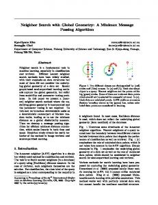
The Argo packet switched NoC for message passing implements end-to-end virtual channels and DMA controllers in the processor nodes. The processor can set up a DMA controller to push a block of data from the local SPM into the SPM of a remote processor core. This is the fundamental hardware mechanism underlying our message-passing library. A range of multicore platforms including [25], [21] provide similar functionality to Argo. The processor needs to set up a communication channel to communicate between two processors. The Argo NoC uses static TDM scheduling for routing communication channels in routers and on links. The repeating schedule is an assignment between communication channels, DMA controllers, and TDM slots. In every time slot the NI can transmit a short packet with a two-word payload. The NI sends larger blocks of data (i.e., messages) as a sequence of packets. In this way all the outgoing channels from a processor node can be active at the same time in a time-multiplexed fashion. In contrast to other TDM based NoCs that require creditbased flow control across the virtual channels, we have been able to avoid all forms of flow control and buffering in hardware. We achieve this by a novel network interface (NI) design [10] that integrates the DMA controllers with the TDM scheduling in the NIs as illustrated in Figure 1. In a given time slot of the TDM schedule, the corresponding DMA controller reads two words of payload data from the SPM and injects a packet into the NoC. This packet traverses the NoC and when it arrives at the destination the NI writes it directly to the SPM. We have implemented the DMA controllers in a single time-shared DMA state machine, because only one controller is active in each TDM slot. The design stores the address pointers and the word count corresponding to one logical DMA controller in a table. This sharing of the DMA controller hardware, and the absence of flow control and buffering, results in an extremely small hardware implementation; the NI is 2-3 times smaller than existing designs offering similar functionality [10]. At the same time the design supports a globally-asynchronous locally-synchronous platform with a minimum of clock-domain crossings.
Processor Inst
Mem_Data
M$
D$
MP_Data
S$ SPM Read Write
TDM sch. Other Processor Nodes
DMA Table
Network Interface
...
MemoryTree
Bi−torus NOC Router
Memory Controller
SRAM Fig. 1. Block diagram of a node in the T-CREST multicore processor and its connections to the memory tree NoC and the message passing NoC.
should force the programmer to keep data locally, reducing the use of the shared memory as much as possible. IV. T HE T-CREST P LATFORM This section gives an overview of the T-CREST multicore platform and a more in-depth presentation of the hardware functionality of the message passing NoC and the associated TDM scheduler. A. Platform Overview The Patmos multiprocessor is a time-predictable homogeneous multiprocessor platform. It is designed to be a generalpurpose platform for real-time systems, but it is also possible to instantiate application-specific FPGA implementations. Figure 1 shows the structure of a Patmos processor node. Each processor node contains three caches and three SPMs: a method cache (M$), a stack cache (S$) for stack allocated data, a data cache (D$) for heap allocated and static data, and SPMs for instructions, data, and message passing communication. Patmos can also bypass caches and directly access the shared memory. The platform has two NoCs, one that provides access to a shared memory, and one that supports inter-core communication. We refer to these NoCs as the memory tree NoC (due to its structure) and the message passing NoC. Both NoCs use TDM to guarantee latency and bandwidth. The processor has two address spaces: (i) a globally shared address space, and (ii) a local I/O address space for I/O devices and local SPM data. Accesses to the globally shared address space go through the memory tree NoC.
C. The Scheduler The off-line scheduler [13] generates a TDM schedule for a given application. Input to the scheduler is a communication graph that specifies groups of tasks mapped to the same processor (nodes in the graph), and the communication channels (edges annotated with the required bandwidth) along with a mapping of groups of tasks to specific processors in the platform. Using a meta-heuristic optimization algorithm, the scheduler minimizes the period length of the generated schedule. In general, the schedule period depends on the number of processor nodes and channels. It is interesting to note that a schedule for a fully connected communication graph with the same bandwidth requirement on all channels is 19 slots for a 16-node platform and 85 slots for a 64-node platform.
53
The scheduler supports arbitrary NoC topologies, arbitrary pipelining in the individual routers and links, and different sized packets on different channels.
receiver. The message itself has this flag set (by the sender). The receiver polls this flag to detect when the message has arrived. Then the flag is reset again.
V. D ESIGN
C. Flow Control
A user-friendly message passing library shall hide all the complicated and the platform-specific details from the programmer, such that the programmer can concentrate on the application design. The programmer should not have to take care of hiding communication latency or preventing message buffers from overflowing. The library should hide these details from the programmer without inferring significant overhead and while maintaining the analyzability of the whole system. When we designed the TPMP library we assumed a platform similar to the T-CREST platform, with simple DMA-driven NIs [10].
To implement flow control, the receiver needs to acknowledge that it has received the previous message, such that the sender can send a new message. To avoid flow control on the acknowledge message, we need an acknowledgement scheme where consecutive acknowledgements can be overwritten without losing data. Such a scheme can be a simple counter, counting the number of messages the receiver has acknowledged. Every time the receiver acknowledges a message, the library updates the counter and sends the value of the counter to the sender. The sender can then calculate if there is any free buffer space at the receiver, by subtracting the number of acknowledged messages from the number of messages sent. The acknowledgment message uses the very same push communication as described above for the message transfer. It is not different from a normal data packet.
A. Requirements The overall requirements to the TPMP library are timepredictability, ease-of-use, and low overhead. To be timepredictable it shall be possible to compute the end-to-end latency of a message transfer. This end-to-end latency depends on the size of the message, the bandwidth allocated for the communication channel, and the code running on the processors involved in the communication. The communication primitives shall be implemented such that they minimize the WCET. Ease-of-use means that the interface functionality shall be designed to fit many different applications. The interface shall provide communication primitives with different levels of configurability, such that the application developer can choose which runtime checks to perform in the application. In a low overhead design it is important to avoid unnecessary movement of data. If the message data is moved to the shared memory it might be evicted from the caches, which can lead to a very high WCET. Even if the data stays resident in the cache, WCET analysis might not be able to classify those accesses as cache hits.
D. Point-to-Point Primitives Point-to-point communication involves two processors, the sender and the receiver. To make point-to-point communication efficient, the library needs to double buffer the messages to interleave communication and computation. To take advantage of the overlapping in both ends of the point-to-point communication channel, both the sender and receiver need to have two buffers. These four buffers comprise one for the sender to write into, two for the network to operate on, and one for the receiver to read from. The sender needs to keep track of its own double buffer and it needs to coordinate with the receiver where to write into the receiver’s double buffer. We construct the double buffering as a circular buffer. To control the circular buffer at the receiver the sender needs a pointer to the tail of the queue and the receiver needs a pointer to the head of the queue. With the flow control described in Subsection V-C, the only check the primitives have to make is to reset the head or tail pointer when they reach the end of the circular buffer space. To increase the flexibility of the point-to-point communication primitives and to support a larger set of programming models, we add buffers to the existing double buffer and use the available handling of the circular buffers. The number of buffers is configurable on a per channel basis. We can add additional capacity either to the sender side or to the receiver side. If we add the buffer capacity to the sender circular buffer, the sending processor needs to handle every message twice. Once to enqueue the message and once to setup the DMA transfer for that message. Therefore, we add the buffer capacity to the receiver circular buffer where we can wait for a message and dequeue the message in a single step. As we already have circular buffers for the double buffering, it is straightforward to increase the size of the circular buffers.
B. Push Communication To push data to another core we need to setup a DMA transfer. We need four parameters to setup the DMA transfer: (1) the local address, (2) the destination core, (3) the remote address, and (4) the amount of data that the DMA should transfer. After this setup, the DMA and NoC transfer the message without any processor interaction. The sender can poll the DMA to detect the completion of the push message transfer. On the receiving side the NI moves the message data to the destination address in the SPM without any interaction between the processor and the NI. The NoC and NI do not support any notification of a completed message transfer. Therefore, we need to implement this notification of the completed message transfer in software on top of the pure push communication. The NI transfers the message data in-order, so when the processor detects the last word of a transfer, it knows that it has received the complete message. Therefore, we append one word for a flag to the end of a message that is initially cleared by the
54
Data struct allocated in sender SPM
Write buffer 1
Data struct allocated in receiver SPM
Barrier Flag 1 Barrier Flag 2
Read buffer 1 Barrier Flag N
Receive flag
Receive flag
Write buffer 2
Read buffer 2
Receive flag Acknowledge count
Receive flag
Fig. 3. The memory layout of the collective communication primitives.
Read buffer N
The non-blocking send primitive can fail for two reasons, either there is no free buffer at the receiver end, or there is no free DMA on the sender side to transfer the data. The non-blocking receive and acknowledge primitives can each fail for one reason. If the buffer queue is empty, the nonblocking receive primitive fails. If there is no free DMA to transfer the Acknowledge count to the sender, the nonblocking acknowledge primitive fails. With the error codes the application programmer can take action depending on the error.
Data Exchange Area
Data Exchange Flag
Receive flag Acknowledge count Fig. 2. The memory layout of the buffering structure for point-to-point communication primitives.
E. Collective Primitives The basic collective primitive is a barrier. All cores in a group call the barrier function for synchronization. The semantics of a barrier is that none of the participating tasks can advance beyond the barrier before all tasks have called the barrier function. Broadcast, all-to-all, reduce, and reduce-all are examples of extended primitives. The semantics of these extended primitives are a barrier synchronization followed by a data exchange. The differences between these extended primitives are the data exchange patterns. We have implemented the broadcast to show the basic operation, and with the following ideas we can easily implement the other extended collective primitives. As the extended collective primitives start with a barrier, the tasks have to finish using the data of the previous exchange before calling the next collective primitive. Therefore, there is no need for flow control; we only need a packet arrival notification. Or in other words, the barrier serves as flow control. a) Barrier: A barrier has two phases: notify and wait. In the notify phase the task will notify the task group that it has reached the barrier. In the wait phase the task will wait for a notification from all the tasks in the group. When a task has seen all members of its group arrive at the barrier, it can continue its execution. We can implement a notification to all members of a group by sending a message to each of them. With an all-to-all TDM schedule in the NoC the bandwidth is already allocated and the individual communication channels do not interfere. Therefore, each member in the group sends a flag to every other member. Figure 3 shows the memory layout for the collective primitives in each SPM. The barrier uses only the barrier flags.
The acknowledgement scheme described in Subsection V-C together with the added buffer capacity allows the receiver to receive two or more messages before acknowledging any of these messages. Figure 2 shows the memory layout of the two communication data structures allocated in the SPMs. The application programmer can configure the number of read buffers of the point-to-point channel to match the needs of the application. The library hides the communication latency from the sender, by overlapping computation and communication in two write buffers. The Acknowledge count in the receiver SPM is the number of messages that the receiver has acknowledged. The acknowledge primitive transfers the local Acknowledge count to the remote Acknowledge count in the sender SPM using push communication. The sender can compute the number of free buffers in the receiver side message queue from the number of messages sent and the number of messages acknowledged. After using the data in a buffer, the receiver sends the acknowledgement for this buffer back to the sender. An acknowledgement means that the point-to-point connection can reuse the acknowledged receive buffer for new data. For the point-to-point communication there are three primitives, (1) a send primitive, (2) a receive primitive, and (3) an acknowledge primitive. For each primitive there is a blocking and a non-blocking version. The blocking communication primitives complete when all conditions are meet. The nonblocking versions check the conditions and return a success or a failure code depending on the failing condition.
55
b) Broadcast: With the help of the barrier we can implement a broadcast. The broadcast starts with a barrier and then the root process of the broadcast transmits a block of data to all the other participants in the broadcast. We place the broadcast data in the data exchange area of the root process, as seen in Figure 3. The broadcast primitive transfers this data to the participants’ SPMs by setting up a DMA transfer for each participant.
Sender
mp_send()
Receiver
mp_recv()
return Producing data mp_send()
return
Using data mp_ack()
VI. A NALYZABLE I MPLEMENTATION Processing
Our main target for the implementation of the TPMP library is its WCET analyzability. During the development we use AbsInt’s aiT WCET analysis tool [26] to guide development decisions. First, we bound all loops to enable WCET analysis. Second, cache misses are very costly on a time-predictable multicore processor. Therefore, we tried to avoid accessing shared memory completely, by allocating as many data structures as possible in the processor local SPM.
return Producing data
mp_recv()
return Using data
Fig. 4. A model of the implemented point-to-point communication.
A. Push Communication
Application code
The Argo NoC implements push communication in hardware, but does not generate a notification when a message is received. We implement the receive notification in a single 32-bit value at the end of each message. Adding the receive notification does not change the way we analyze the communication.
Barrier preamble Barrier synchronization
B. Flow Control Our design implements flow control by sending a counter value from the receiver to the sender. The library sends this counter value in a single network flit (64 bits of unsigned data), with no receive flag as notification. Calculating the number of free buffers is safe across an overflow, as long as the overflow value is greater than the largest possible difference between the two unsigned values, i.e., the number of buffers in the queue.
Barrier postamble
Application code
Fig. 5. A model of the implemented barrier primitive.
C. Point-to-Point Primitives
D. Barrier Primitive
Figure 4 shows the interaction between two communicating threads using the blocking point-to-point primitives. When mp_send() sets up the DMA, the NI starts to transmit packets to the receiver. After receiving all packets the blocking mp_recv() continues. When the receiver finishes using the received message, it updates the Acknowledge count and sends it to the sender. Depending on the number of free elements in the buffer queue, the sender may proceed. To analyze the blocking primitives, we assume that the blocking primitives do not have to wait for messages to arrive or free buffer space. We bounded the unbounded while loops in the blocking point-to-point primitives with source code annotations. We set the upper loop bound of the while loops to one. The analysis method presented in [24] supports this interaction enabling worst-case response time analysis. The implementation of the non-blocking point-to-point primitives is free of unbounded loops. Therefore, the source code needs no annotations to complete the analysis. We minimized the WCET for all primitives by looking at the feedback from the interactive analysis in the aiT tool.
Figure 5 shows the interaction between cores that participate in a barrier. First, the barrier preamble calculates the addresses of the flags to send to the other participants. Then, it sends a message with a flag to all the others. When the primitive has set up all messages for transfer, the core synchronizes with the other cores one by one. To separate subsequent barrier calls, the primitive needs to reset the flag; resetting the flag requires the cores to synchronize a second time. To avoid resetting the flag twice, we make use of sense switching, first described by Hensgen [27]. Sense switching combines an alternating phase with the flag. E. Broadcast Primitive Figure 6 shows the model of the broadcast primitive. The broadcast primitive starts by synchronizing all cores with a barrier call. After the barrier call, the root of the broadcast pushes data to the other cores by setting up one DMA transfer to each of them. The cores receiving data from the root core wait for the receive flag.
56
A key observation is that this only happens if the NI writes a new value in the same cycle, and that this only happens when there is at least one free buffer in the receiver. By restricting to sending only a single message after a read of the count value, the sending processor can draw one of two conclusions and both are on the safe side: (i) If a potentially incorrect count value causes the sender to conclude that the receiver does not have a free buffer, then the sender will continue waiting and polling, and at the next read of the count it will read the correct value. (ii) If the potentially incorrect count value causes the sender to conclude that the receiver does have at least one free buffer, then – despite the incorrect count value – this conclusion is actually correct. In both cases the behavior is correct, and in the worst case the additional polling operation adds a few cycles to the latency of the send operation. If the processor and NI are in different clock domains it is not only a matter of reading potentially undefined digital values. It is also a matter of metastability and reading non-digital signals. Handling of this situation requires synchronization of signals/flags to the processor clock domains. Implementing this involves a minor addition to the NI implementation and this is future work. However, the effect on the WCET analysis as presented in this paper will be very small.
Application code
Barrier preamble Barrier synchronization
Broadcast preamble Broadcast data Broadcast postamble Application code
Fig. 6. A model of the implemented broadcast primitive.
F. Concurrency Issues The SPM has two independent read/write ports that are used by the processor and by the NI. The processor and the NI behave as two truly concurrent threads: a software thread and a hardware thread. Both threads can access the same memory cell in the exact same clock cycle. Reading concurrently is not an issue. Writing concurrently will result in an undefined value. The TPMP library avoids concurrent writes by design. The remaining issue is reading and writing concurrently. Most FPGA technologies do not define the result of a read during a write to the same address at the same time. An undefined value may be a random mix of the old value and the new value, but the stored value will be the new value [28], [29]. Reading an undefined value from the SPM might cause wrong behavior by the communication primitives. In the design, discussed in Section V, a processor can read an undefined value when reading the receive flag or the acknowledge count. The DMA controller of the NI will never read an undefined value as the processor starts the DMA only after the processor has written all the data. If the NI and the processor reside in the same clock domain, we can solve the problem of reading an undefined value in hardware by adding forwarding to the SPM, from the network port to the processor port; but with the implementation of our TPMP library this is not necessary. The receive flag arrives only after the NoC has delivered all the message data. If the processor reads the receive flag in the same cycle as the flag arrives, the processor reads an undefined value; 0 or 1. If the processor reads a 1 it correctly concludes that it has received a message. If it reads a 0 it will continue waiting and polling at the next try it will read a 1. This adds only a few cycles to the receive operation. For the acknowledgment the receiver communicates back to the sender, the situation is somewhat similar, but more complex. The count value may signal the availability of one or more free buffers and the processor may read an arbitrary value.
VII. E VALUATION For the WCET analysis and the measurements we use a 9-core platform with a 3×3 bi-torus network and a TDM arbiter for shared memory access. Each core in the platform is running at 80 MHz and has 4 KB of communication SPM. The platform is running in an Altera Cyclone IV FPGA with 2 MB of external SRAM. The cache miss time with the TDM arbiter is 189 clock cycles for a 16-byte burst. We computed the WCET numbers with the aiT tool from AbsInt [26], which supports the Patmos processor architecture. For the average-case execution time (ACET) results, we ran a test application in the described hardware, reading out the clock cycle counter to get the timing. For these results we assume that the functions are resident in the method cache. We optimized the source code of the TPMP library functions with respect to WCET by looking at the feedback from the interactive mode of the aiT tool. A. Point-to-Point Primitives Table I shows the measured ACET and the WCET of all library functions. Each blocking function contains a while loop that blocks until a condition becomes true. The design section describes the conditions of each primitive. We assume that the functions do not wait for any of these conditions to become true. A system-level analysis will show if our assumption does not hold and in this case we can add the delay found by the system level analysis to the WCET. For the WCET analysis we bounded the loop iteration count to one. As shown in Table I the WCETs of the blocking function calls are higher than the WCETs for the non-blocking calls. This is because the if statement in the non-blocking primitive use predicates, avoiding a conditional branch.
57
TABLE II T HE WORST- CASE LATENCY IN CLOCK CYCLES OF SENDING A MESSAGE , WITHOUT ACKNOWLEDGEMENT OF MESSAGES , FOR THE BLOCKING AND NON - BLOCKING COMMUNICATION PRIMITIVES .
TABLE I AVERAGE - CASE EXECUTION TIME (ACET) AND WORST- CASE EXECUTION TIME (WCET) FOR EACH POINT- TO - POINT COMMUNICATION PRIMITIVE . Function mp_nbsend() mp_send() mp_nbrecv() mp_recv() mp_nback() mp_ack()
WCET (cycles)
51 74 32 28 55 49
83 99 36 43 59 77
Message size (bytes) Blocking Non-blocking
7000 6000 5000 4000 3000 2000 1000 0 2
8
32
128
512
2048
211 188
301 278
661 678
2101 2078
7861 7838
We assume that the clock frequency of the processors and the NoC is the same to shorten the formula. One could extend the formula to account for multiple frequencies, but we omit this here for space reasons. Lmsg is the worst-case latency in clock cycles from the time the source processor calls mp_send() to the time the destination processor returns from mp_recv(), assuming that the sender does not wait for a free buffer or a free DMA, and the receiver is ready to call mp_recv(). A system-level analysis can find any delays that break these assumptions and add them to the worst-case latency. Lmsg consists of two parts: (1) the WCET of the code running on the processors and (2) the latency of a write transaction [30]. Table I shows the WCET of the communication primitives and Equation 1 shows the formula for the latency Lwrite of a write transaction. �� � � Smsg Lwrite = (1) · PTDM ·Cslot + H · D Schan
Tournament (WCET) Message passing (WCET) Tournament (ACET) Message passing (ACET)
8000 Execution time (clock cycles)
ACET (cycles)
4 6 8 Number of cores participating in barrier
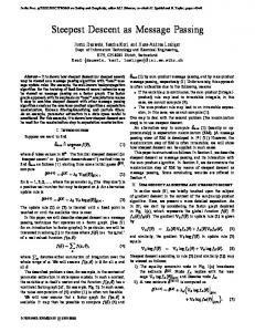
Fig. 7. The measured average-case execution time and the worst-case execution time of a barrier call as a function of the number of cores participating in the barrier.
Smsg is the size of the transmitted message, Schan is the number of payload bytes that the NoC can send in one TDM period from the source processor to the destination processor, PTDM is the length of the TDM period, Cslot is the number of clock cycles in a TDM slot, H is the number of hops from the source to the destination processor, and D is the number of phits that one router can store. With our Argo NoC Schan is 8 bytes and Cslot is 3 clock cycles, meaning that two 32-bit words can transferred every 3 clock cycles. For the synchronous version of the Argo router D is 3 phits. For the presented 3×3 core platform H is at most 3 hops. With an all-to-all schedule for this platform, PTDM is 10 time slots. Smsg is the message size. To the latency of a DMA transfer we add the WCET of sending and receiving the message. The WCET of sending and receiving does not depend on the size of the message, because it does not involve moving the data. Table II shows the worst-case latency of sending a message from a sender to a receiver. The designer can reduce the latency of transmitting large messages considerably by generating an application specific schedule that reduces PTDM .
The WCET is relatively close to the measured averagecase execution time because the platform is optimized for time predictability. The execution time is a few tens of clock cycles. The library code is efficient, as no data needs to be copied between the user program and the message-passing library. All buffers in the SPM are directly usable for computation and communication. B. Barrier Comparison Figure 7 shows the WCET and the ACET of our messagepassing barrier against a tournament barrier [27]. The hardware platform is the same for all the measurements; the number of cores is the number of cores participating in the barrier. This figure shows that our barrier implementation using message passing is faster than the shared memory tournament barrier in both the worst case and the average case. Furthermore, message passing scales better in the number of cores. C. End-to-End Latency We can calculate the end-to-end latency of transmitting a message from one core to another with our library by adding the WCET of the executed code and the time it takes the DMA to transfer the data. We refer to this latency as Lmsg . Gangwal et al. [30] show how to calculate the latency of a write transaction through a TDM NoC. With an all-to-all TDM schedule, where all communication channels have equal bandwidth, this formula simplifies to what we show below.
VIII. C ONCLUSION Real-time systems need time-predictable computing platforms. For a multicore processor not only the processor needs to be time-predictable, but also the message passing hardware and software. This paper presented a message-passing library for a time-division multiplexed network-on-chip. We developed the library to be time-predictable and we show this by analyzing
58
the code with the aiT WCET analysis tool from AbsInt. As the design carefully avoids access to shared memory in the library code, the resulting WCET for the message passing primitives is in the order of tens of clock cycles. The message passing library and the application code operate on data allocated in a local scratchpad memory that the networkon-chip also use for data transmission. Therefore, the message passing library does not need to copy data and the WCET of the message passing functions is less than 100 clock cycles, independent of the message size.
[11] M. Schoeberl, F. Brandner, J. Sparsø, and E. Kasapaki, “A statically scheduled time-division-multiplexed network-on-chip for real-time systems,” in Proceedings of the 6th International Symposium on Networks-on-Chip (NOCS). Lyngby, Denmark: IEEE, May 2012, pp. 152–160. [12] R. B. Sørensen, M. Schoeberl, and J. Sparsø, “A light-weight statically scheduled network-on-chip,” in Proceedings of the 29th Norchip Conference. Copenhagen: IEEE, November 2012. [13] R. B. Sørensen, J. Sparsø, M. R. Pedersen, and J. Hojgaard, “A metaheuristic scheduler for time division multiplexed networks-on-chip,” in Object/Component/Service-Oriented Real-Time Distributed Computing (ISORC), 2014 IEEE 17th International Symposium on, June 2014, pp. 309–316. [14] MPI-forum, MPI: A Message-Passing Interface Standard Version 3.0. MPI-forum, 2012, available at http://www.mpi-forum.org/docs/mpi-3.0/ mpi30-report.pdf. [15] Intel Labs, “SCC external architecture specification (EAS),” Intel Corporation, Tech. Rep., May 2010. [16] ——, “The SCC programmer’s guide,” Intel Corporation, Tech. Rep., January 2012. [17] T. Mattson and R. van der Wijngaart, “RCCE: a small library for manycore communication,” Intel Corporation, Tech. Rep., 2010. [18] J. Scheller, “Real-time operating systems for many-core platforms,” Master’s thesis, Institut supérieur de l’aéronautique et de l’espace, Toulouse, France, 2012. [19] W. Puffitsch, E. Noulard, and C. Pagetti, “Mapping a multi-rate synchronous language to a many-core processor,” in Proceedings of the 19th Real-Time and Embedded Technology and Applications Symposium, ser. RTAS ’13. IEEE, 2013, pp. 293–302. [20] M. Kang, E. Park, M. Cho, J. Suh, D. Kang, and S. P. Crago, “MPI performance analysis and optimization on Tile64/Maestro,” in Proceedings of Workshop on Multi-core Processors for Space—Opportunities and Challenges Held in conjunction with SMC-IT, 2009, pp. 19–23. [21] K. Goossens, A. Azevedo, K. Chandrasekar, M. D. Gomony, S. Goossens, M. Koedam, Y. Li, D. Mirzoyan, A. Molnos, A. B. Nejad, A. Nelson, and S. Sinha, “Virtual execution platforms for mixed-time-criticality systems: The CompSOC architecture and design flow,” SIGBED Rev., vol. 10, no. 3, pp. 23–34, Oct. 2013. [22] A. Kanevsky, A. Skjellum, and A. Rounbehler, “Mpi/rt-an emerging standard for high-performance real-time systems,” in System Sciences, 1998., Proceedings of the Thirty-First Hawaii International Conference on, vol. 3. IEEE, 1998, pp. 157–166. [23] A. Skjellum, A. Kanevsky, Y. S. Dandass, J. Watts, S. Paavola, D. Cottel, G. Henley, L. S. Hebert, Z. Cui, and A. Rounbehler, “The real-time message passing interface standard (MPI/RT-1.1),” Concurrency and Computation: Practice and Experience, vol. 16, no. S1, pp. Si–S322, 2004. [24] D. Potop-Butucaru and I. Puaut, “Integrated Worst-Case Execution Time Estimation of Multicore Applications,” in 13th International Workshop on Worst-Case Execution Time Analysis, ser. OpenAccess Series in Informatics (OASIcs), C. Maiza, Ed., vol. 30. Dagstuhl, Germany: Schloss Dagstuhl–Leibniz-Zentrum fuer Informatik, 2013, pp. 21–31. [25] M. Kistler, M. Perrone, and F. Petrini, “Cell multiprocessor communication network: Built for speed,” Micro, IEEE, vol. 26, pp. 10–25, 2006. [26] R. Heckmann and C. Ferdinand, “Worst-case execution time prediction by static program analysis,” AbsInt Angewandte Informatik GmbH, Tech. Rep., [Online, last accessed November 2013]. [27] D. Hensgen, R. Finkel, and U. Manber, “Two algorithms for barrier synchronization,” International Journal of Parallel Programming, vol. 17, no. 1, pp. 1–17, 1988. [28] A. Corporation, “Stratix V device handbook, volume 1: Device interfaces and integration,” Altera Corporation, Tech. Rep., 2014. [29] I. Xilinx, “Spartan-6 FPGA block RAM resources user guide,” Xilinx, Inc., Tech. Rep., 2011. [30] O. Gangwal, A. R˘adulescu, K. Goossens, S. González Pestana, and E. Rijpkema, “Building predictable systems on chip: An analysis of guaranteed communication in the aethereal network on chip,” in Dynamic and Robust Streaming in and between Connected Consumer-Electronic Devices, ser. Philips Research, P. van der Stok, Ed. Springer Netherlands, 2005, vol. 3, pp. 1–36.
ACKNOWLEDGMENTS The work presented in this paper was funded by the Danish Council for Independent Research | Technology and Production Sciences under the project RTEMP,1 contract no. 12-127600. S OURCE ACCESS The presented work is open source and the full T-CREST tool chain can be downloaded from GitHub and built under Ubuntu with the following two commands: git clone https://github.com/t-crest/patmos-misc.git misc ./misc/build.sh
R EFERENCES [1] R. Kumar, T. G. Mattson, G. Pokam, and R. Van Der Wijngaart, “The case for message passing on many-core chips,” in Multiprocessor System-onchip: Hardware Design and Tool Integration, M. Hübner and J. Becker, Eds. Springer, 2011, ch. 5, pp. 115–123. [2] T. G. Mattson, R. F. Van der Wijngaart, M. Riepen, T. Lehnig, P. Brett, W. Haas, P. Kennedy, J. Howard, S. Vangal, N. Borkar, G. Ruhl, and S. Dighe, “The 48-core SCC processor: the programmer’s view,” in International Conference for High Performance Computing, Networking, Storage and Analysis (SC), 2010, pp. 1–11. [3] M. Schoeberl, C. Silva, and A. Rocha, “T-CREST: A time-predictable multi-core platform for aerospace applications,” in Proceedings of Data Systems In Aerospace (DASIA 2014), Warsaw, Poland, June 2014. [4] M. Schoeberl, P. Schleuniger, W. Puffitsch, F. Brandner, C. W. Probst, S. Karlsson, and T. Thorn, “Towards a Time-predictable Dual-Issue Microprocessor: The Patmos Approach,” in Bringing Theory to Practice: Predictability and Performance in Embedded Systems, ser. OASICS 18 Schloss Dagstuhl - Leibniz-Zentrum fuer Informatik, vol. 18, Mar 2011, pp. 11–21. [5] M. Schoeberl, D. V. Chong, W. Puffitsch, and J. Sparsø, “A timepredictable memory network-on-chip,” in Proceedings of the 14th International Workshop on Worst-Case Execution Time Analysis (WCET 2014), 2014. [6] J. Garside and N. C. Audsley, “Investigating shared memory tree prefetching within multimedia noc architectures,” in Memory Architecture and Organisation Workshop, 2013. [7] M. D. Gomony, B. Akesson, and K. Goossens, “Architecture and optimal configuration of a real-time multi-channel memory controller,” in Design, Automation Test in Europe Conference Exhibition (DATE), 2013, 2013, pp. 1307–1312. [8] E. Lakis and M. Schoeberl, “An SDRAM controller for real-time systems,” in Proceedings of the 9th Workshop on Software Technologies for Embedded and Ubiquitous Systems, 2013. [9] E. Kasapaki, J. Sparsø, R. B. Sørensen, and K. Goossens, “Router designs for an asynchronous time-division-multiplexed network-on-chip,” in Digital System Design (DSD), 2013 Euromicro Conference on. IEEE, 2013, pp. 319–326. [10] J. Sparsø, E. Kasapaki, and M. Schoeberl, “An area-efficient network interface for a TDM-based network-on-chip,” in Design, Automation Test in Europe Conference Exhibition (DATE), 2013, March 2013, pp. 1044–1047. 1 http://rtemp.compute.dtu.dk
59