Apr 3, 2012 - Falls, ID (US); Montana Tech of the. University of Montana, Butte, MT. FOREIGN PATENT DOCUMENTS. (US); Qualtech Systems, Inc., East. JP.
(12)
United States Patent
No.: US 8,150,643 B1 Apr. 3, 2012 (45) Date of Patent: (1o) Patent
Morrison et al.
(56)
(54) METHOD OF DETECTING SYSTEM FUNCTION BY MEASURING FREQUENCY RESPONSE (75)
Inventors: John L. Morrison, Butte, MT (US); William H. Morrison, Manchester, CT (US); Jon P. Christophersen, Idaho Falls, ID (US)
(73)
Assignees: Battelle Energy Alliance, LLC, Idaho Falls, ID (US); Montana Tech of the University of Montana, Butte, MT (US); Qualtech Systems, Inc., East Hartford, CT (US)
(*)
Notice:
U.S. PATENT DOCUMENTS 5,061,890 A 10/1991 Longini 5,406,496 A 4/1995 Quinn 5,454,377 A 10/1995 Dzwonczyk et al. 5,512,832 A 4/1996 Russell et al. 5,946,482 A 8/1999 Barford et al. 6,208,147 BI 3/2001 Yoon et al. 6,249,186 BI* 6/2001 Ebihara et al ................. 330/277
(Continued) FOREIGN PATENT DOCUMENTS JP
2000-009817 A
1/2000
OTHER PUBLICATIONS FreedomCar Battery Test Manual, manual, Oct. 2003, Idaho National Laboratory, 25 pages.
Subject to any disclaimer, the term of this patent is extended or adjusted under 35 U.S.C. 154(b) by 272 days.
(Continued) Primary Examiner Hal Wachsman (74) Attorney, Agent, or Firm TraskBritt
(21) Appl. No.: 12/217,013 (22) Filed:
References Cited
Jun. 30, 2008
(57) ABSTRACT Real-time battery impedance spectrum is acquired using a one-time record. Fast Summation Transformation (EST) is a parallel method of acquiring a real-time battery impedance spectrum using a one-time record that enables battery diagnostics. An excitation current to a battery is a sum of equal amplitude sine waves of frequencies that are octave harmonics spread over a range of interest. A sample frequency is also octave and harmonically related to all frequencies in the sum. The time profile of this signal has a duration that is a few periods of the lowest frequency. The voltage response of the battery, average deleted, is the impedance of the battery in the time domain. Since the excitation frequencies are known and octave and harmonically related, a simple algorithm, EST, processes the time record by rectifying relative to the sine and cosine of each frequency. Another algorithm yields real and imaginary components for each frequency.
Related U.S. Application Data (63) Continuation-in-part of application No. 11/825,629, filed on Jul. 5, 2007, now Pat. No. 7,395,163, which is a continuation of application No. 11/313,546, filed on Dec. 20, 2005, now abandoned. (60) Provisional application No. 60/637,969, filed on Dec. 20, 2004, provisional application No. 60/724,631, filed on Oct. 7, 2005. (51) Int. Cl. (2006.01) (2006.01) (52) U.S. Cl . ............. 702/75; 702/79; 702/117; 324/603 (58) Field of Classification Search .................... 702/75, 702/117,79 See application file for complete search history. GOIR 23100 G06F 11/00
12 Claims, 22 Drawing Sheets
select numberoften frequencies to test unit
10
1 12
assemble chosen frequencies into an Excitation Time Record (ETR) 1 condition ETR to unit to be tested
_1
14
l excite unit with ETR andsimultaneously capture Response Time Record (RTR)
16
I process RTR with s ynchronous detection equations to estimate frequency components ofmagnitude and phase for each test frequency
18
1 reassemble estimated frequency components to obtain Estimated Response Time Record (ERTR)
20
1 subtract ERTR from RTR to get error
22
1 minimize error to get the frequency response of the unit
24
US 8,150,643 B1 Page 2 U.S. PATENT DOCUMENTS 6,262,563 B1 6,307,378 B1 6,481,289 B2 6,653,817 B2 6,832,171 B2 7,065,474 B2 * 7,395,163 B1 7,616,003 B2 7,675,293 B2 2003/0206021 Al* 2005/0127908 Al 2005/0182584 Al 2007/0257681 Al 2008/0303528 Al 2010/0274510 Al 2010/0332165 Al
7/2001 10/2001 11/2002 11/2003 12/2004 6/2006 7/2008 11/2009 3/2010 11/2003 6/2005 8/2005 11/2007 12/2008 10/2010 12/2010
Champlin Kozlowski Dixon et al. Tate, Jr. et al. Barsoukov et al. Petchenev et al . ............ 702/190 Morrison et al. Satoh et al. Christophersen et al. Laletin et al . ................. 324/426 Schlicker et al. Plusquellic Christophersen et al. Kim Morrison et al. Morrison et al.
OTHER PUBLICATIONS Ronald C. Fenton, BSM Development Documentation Senior Project Final Report for the Idaho National Laboratory, May 2005, Montana Tech of the University of Montana, 13 pages. W. Morrison, Intelligent Self-Evolving Prognostic Fusion, Phase I STTR Interim Report, Jul. 2005, Qualtech Systems, Inc., 46 pages. Weston, Albreht, Battery Complex Impedance Identification with Random Signal Techniques, 2005, Montana Tech of the University of Montana. 99 pages. J. Morrison, Algorithms as MATLAB Code for Real Time Estimation of Battery Impedance, Sep. 2005, Montana Tech of the University of Montana, 21 pages. R. E. Ziemer, W. H. Tranter, Principles of Communcations 5th edition, John Wiley & Sons, 2002, 11 pages. P. D. Wasserman, Advanced Methods in Neural Computing, 1993, New York: Van Nostrand Reinhold. 31 pages. Alpaydin, Introduction to Machine Learning, 2004, Cambridge, Mass., London, England, The MIT Press. 8 pages. J. L. Morrison, W. H. Morrison, Real Time Estimation of Battery Impedance, IEEE Aerospace Conference, Mar. 5-11, 2006, Big Sky, MT, 13 pages Nikolopoulos, P. N., Accurate Method of Representation of HighVoltage Measuring Systems and its Application in High-ImpulseVoltage Measurements, Mar. 1989, 66-72, vol. 136, Science, Measurement and Technology, IEE Proceedings A, Dept. of Electr. Eng., Nat. Tech. Univ., Athens, Greece. Smith, R., Banaszuk, A., Dullerud, G., Model Validation Approaches for Nonlinear Feedback Systems Using Frequency Response Measurements, Dec. 1999, 1500-1504, vol. xvii+5325, Decision and Control, Proceedings of the 38th IEEE Conference, Phoenix, AZ.
Jon P. Christophersen, Impedance Noise Identification for State-ofHealth Prognostics, Jul. 7-10, 2008, Philadelphia, PA, 43rd Power Sources Conference, 4 pages. Chapra, "Numerical Methods for Engineers," pp. 394-398, McGrawHill Publishing Company, 1985. Christophersen et al., "Effects of Reference Performance Testing during Aging Using Commercial Lithium-ion Cells," J. Electrochem Soc., 153(7) 2006, pp. A2406-A1416. Christophersen et al., Electrochemical Impedance Spectroscopy Testing on the Advanced Technology Development Program Lithium-ion Cells, 2002, IEEE Trans. Veh. Technol., pp. 1851-1855, 56(3). Christophersen et al., "Lumped Parameter Modeling as a Predictive Tool for a Battery Status Monitor," Oct. 2003, Proceedings from IEEE Vehicular Technology Conference, 6 pages. Mix, Dwight F., "Random Signal Processing," p. 296, Prentice Hall Publishing Company, 1995. Morrison et al., "Fast Summation Transformation for Battery Impedance Identification," IEEE Aerospace 2009 Conference, Mar. 7-14, 2009, Big Sky, Montana, 9 pages. PCT International Search Report and Written Opinion of the International Searching Authority for PCT/US2 0 1 0/03 840 1, dated Dec. 31, 2010, 8 pages. PCT International Search Report and Written Opinion of the International Searching Authority for PCT/US2 0 1 0/03 83 5 8, dated Dec. 31, 2010, 8 pages. PCT International Search Report and Written Opinion of the International Searching Authority for PCT/US11/35052, dated Jul. 26, 2011, 11 pages. Ramos et al., Comparison of impedance measurements in a DSP using ellipse-fit and seven-parameter sine-fit algorithms, Measurement 42 (May 23, 2009) pp. 1370-1379. Retrieved online at . Ranade et al., An overview of harmonics modeling and simulation, Elect. Power Syst. Res. vol. 74, pp. 37-56, Apr. 2005, Retrieved online at . Smyth, Brian, "Development of a Real Time Battery Impedance Measuring System," M.S. Thesis Montana Tech of the University of Montana, 2008, 128 pages. U.S. Appl. No. 13/100,184, filed May 3, 2011 to Christophersen et al., titled, "Crosstalk Compensation in Analysis of Energy Storage Devices." U.S. Appl. No. 13/100,170, filed May 3, 2011 to Christophersen et al., titled, "In-Situ Real-Time Energy Storage Device Impedance Identification."
* cited by examiner
U.S. Patent
Apr. 3, 2012
Sheet 1 of 22
US 8,150,643 B1
Ideal Filter Response 1.4
1.2
rn ro
0.; 11-
0. 31
0.1
0.
1 -1
-0.5
0
0.5
1.5
1
2
Log Frequency
FIG. 1 Ideal Filter Phase
-2
-4
-E Q) t0 a
->
ro ^ -1t
-1:
-1j
-1E
1L -1
-0.5
0
0.5 Log Frequency
FIG. 2
1
1.5
2
U.S. Patent
Apr. 3, 2012
Sheet 2 of 22
US 8,150,643 B1
Uncomp Filter Response A
1. Y
-
1. 2
1
0. 8 rn
m
0. 6-
0. 4
0. 2
D -1
-0.5
0
0.5
1
1.5
1
1.5
2
Log Frequency
FIG. 3 Comp Filter Response 1.^
1.; tF
0.! Mag 0.1
i
0.• I
0.:
-1
-0.5
0
0.5
Log Frequency
FIG. 4
2
U.S. Patent
Apr. 3, 2012
US 8,150,643 B1
Sheet 3 of 22
Compensated Synchronous Detection Phase Response
-20 -40 -60 CO CO
a
-80
a c -100
U
-120 -140 -160 -180
0
-0.5
0.5 Log Frequency
1
1.5
2
FIG. 5
Coo
Ro
a
Vac — fin
Rp
FIG. 6
U.S. Patent
Apr. 3, 2012
US 8,150,643 B1
Sheet 4 of 22
lin
Time sec
FIG. 7 0.25 0.2 0.15 0.1 0.05 VIP 0 -0.0 -0.1 -0.1 -0.2 -0.2 0
0.5
1
1.5
2
2.5 3 Time sec
FIG. 8
3.5
4
4.5
5
U.S. Patent
Apr. 3, 2012
US 8,150 ,643
Sheet 5 of 22
Ideal LPM Response 0
0.[
0
0.[
CO Cm 0 2i 0.[
0
0.[
.2
-1.5
-1
-0.5
0
0.5
1
Log Frequency
FIG. 9 Ideal LPM Phase
a^ m
s Q
f0 a^
-2
-1.5
-1
-0.5
Log Frequency
FIG. 10
0
0.5
1
B1
U.S. Patent
Apr. 3, 2012
US 8,150,643 B1
Sheet 6 of 22
Uncomp LPM Response 0.04
0.035
0.03
0.025
M 0.02
0.015
0.01 0.005 C -2
-1.5
-1
-0.5
0
O.5
1
Log Frequency
FIG. 11 Comp LPM Response 0.
0.0
0.
0.0
0.
0.0
0.
O.0
-2
-1.5
-1
-0.5 Log Frequency
FIG. 12
0
0.5
1
U.S. Patent
Apr. 3, 2012
Sheet 7 of 22
US 8,150,643 B1
Comp Syncr LPM Phase
-5
CD
(n
-10
L
a CL
E L)
-15
-20
-25 L -2
-1.5
-1
-0.5 Log Frequency
FIG. 13
I
Time sec FIG. 14
0
0.5
1
U.S. Patent
Apr. 3, 2012
US 8,150,643 B1
Sheet 8 of 22
0.2E 0.2 0.1 0.1 0.0E YjR 0 -0.0
-0.2 -0.2
0
1
0.5
1.5
2
3 2.5 Time sec
3.5
4
4.5
5
FIG. 15 Ideal LPM Response 0 O.t
0
0.t
M0 0.1
0
0.1
-2
-1.5
-1
-0.5 Log Frequency
FIG. 16
0
0.5
1
U.S. Patent
Apr. 3, 2012
US 8,150 ,643
Sheet 9 of 22
Ideal LPM Phase
m CO CO r EL
m a)
-1.5
-2
-1
U
-U.5
1
U.5
Log Frequency
FIG. 17 Uncomp LPM Response
0
0
0
C
^-2
-1.5
-1
-0.5
Log Frequency
FIG. 18
0
0.5
1
B1
U.S. Patent
Apr. 3, 2012
Sheet 10 of 22
US 8,150,643 B1
Comp LPM Response
0
0 m 0
0
-2
-1.5
-1
-0.5 Log Frequency
0
0.5
1
FIG. 19 Comp Syncr LPM Phase 0
-5
m -10 L Q F-
c° -15
-20
-25 L -2
-0.5 Log Frequency
FIG. 20
0
0.5
1
U.S. Patent
Apr. 3, 2012
US 8,150,643 B1
Sheet 11 of 22
x 10,
4
—'— Neural Network Synchronous Detection
3.5
— Compensated Synchronous Detection Synchronous Detection
3 o -)5 W m
a' c W
2
2 1.5 I 0.5 0
0 Sample Run Number
FIG. 21 x103
4 3.5
—+ Neural Network Synchronous Detection —#— Compensated Synchronous Detection ---* Synchronous Detection
3
W
2.5
a as Cr
2
c
a
1.5 1 0.5 0
0
2
4
6
12 10 8 Sample Run Number
FIG. 22
14
16
18
20
U.S. Patent
Apr. 3, 2012
Sheet 12 of 22
select number of test frequencies to test unit
assemble chosen frequencies into an Excitation "lime Record (ETR)
condition ETR to unit to be tested
excite unit with ETR and simultaneously capture Response Time Record (RTR)
process RTR with synchronous detection equations to estimate frequency components of magnitude and phase for each test frequency
US 8,150,643 B1
10
r— 12
14
16
18
reassemble estimated frequency components to obtain Estimated Response Time Record (ERTR)
20
subtract ERTR from RTR to get error
22
minimize error to get the frequency response of the unit
24
FIG. 23
U.S. Patent
Apr. 3, 2012
US 8,150,643 B1
Sheet 13 of 22
LPM Response, FST*, Ideal o 0.
0. 0. CD Cu
0.
-a a)
E0
0. 0.
O.VL
-0.5
-1
-2
0
0.5
1
Log Frequency FIG. 24A LPM Phase, FST ", ideal o
cc
cc CL
s
-2
-1.5
1
-U.5 Log Frequency
FIG. 24B
U
U-5
1
U.S. Patent
Apr. 3, 2012
Sheet 14 of 22
US 8,150,643 BI
LPkU Nyquiat. FGT~. Ideal o O 'O,QO2 'U.004 -0.00G -O.0O8 CL
^^ 'O.O1 'O.O12 'O.O14 'O.O1G -n ~ ' ~niA
0024 0.026
0.028
0.03
0.032 0.034 0.036 Real
0.038
0I4
FIG. 24C uU,4z
0.038 0.036 cx, ME rs
0.034
^O.032 0.03 0.028 0,026 '1/6
'1
-0.5 Log Frequency FIG, 25A
O
0.5
1
U.S. Patent
Apr. 3, 2012
US 8,150,643 B1
Sheet 15 of 22
LPM Phase, FST x ,
Ideal o
Ca Ca s
a
-2
-1.5
0
-0.5
-1
0.5
1
Log Frequency
FIG 25B LPM Nyquist, FST ", Ideal o 0 -0.002 -0.004 -0.006
d
-0.008
Q E -0.01 -0.012 -0.014 -0.016 -0.018 0.024
0.026
0.028
0.03
0.032 Real
FIG. 25C
0.034
0.036
0.038
U.S. Patent
Apr. 3, 2012
Sheet 16 of 22
US 8,150,643 B1
LPM Response, FST*, Ideal o 0.04 0.038 0.036 0.034 zm
d Q.
0.032
E
0.0-:
0.02E 0.02E 0.024 -2
-1.5
-1
-0.5 Log Frequency
0
0.5
1
0.5
1
FIG. 26A LPM Phase, FST *, Ideal o
0
-5
-10 CD V) Cu L
a
-15
-20
-25 -2
-0.5 Log Frequency
FIG. 26B
0
U.S. Patent
Apr. 3, 2012
US 8,150,643 B1
Sheet 17 of 22
LPM Nyquist, FST *, Ideal o
0 -0.002 -0.004 -0.006 Q C,,
-0.008 -
0.01
-0.012 -0.014 -0.016 -0.018 0.024
0.026
0.028
0.03
0.032
0.034
0.036
0.038
Real
FIG. 26C LPM Res ponse. FST *. Ideal o
0
0 0 m
CO
2E
0
CO 1:2-0
E
I. .W
-
-2
-1.5
-1
-0.5
Log Frequency
FIG. 27A
0
0.5
1
U.S. Patent
Apr. 3, 2012
US 8,150,643 B1
Sheet 18 of 22
LPM Phase, FST *, Ideal o
t a
-2
-1.5
-1
-0.5 Log Frequency
0.5
0
1
FIG. 27B LPM Nyquist, FST *, Ideal o
-0.00 -0.00 -0.00
Q
-0.00
E
-0.0 -0.01 -0.01 -0.01 -0.01 0.025
0.03
0.035 Real
FIG. 27C
0.04
U.S. Patent
Apr. 3, 2012
US 8,150 ,643
Sheet 19 of 22
LPM Response, FST*, Ideal o 0.04' 0.0
0.03' 0.03 0.03 d r E
0.03
O.D
0.02 0.02 0.02 -2
-1.5
-1
-0.5
0
0.5
1
U.^
1
Log Frequency
FIG. 28A LPM Phase, FST ", Ideal o
Cu
m s a
-2
-1.5
.1
-U.5
Log Frequency
FIG. 28B
u
B1
U.S. Patent
Apr. 3, 2012
Sheet 20 of 22
US 8,150,643 B1
LPM Nyquist, FST *, Ideal o 0 -0.002 -0.004 -0.006 X -0.008 C. E
U -0.01 -0.012 -0.014 -0.016 -0.018 0.024
0.026
0.028
0.03
0.032
0.034
0.036
0.038
Real
0.04
FIG. 28C LPM Response, FST*, Ideal o
0.038 0.036 0.034 t to
0.032 _E
0.03 0.028 0.026 0.024 -2
-0.5 Log Frequency
FIG. 29A
0
0.5
1
U.S. Patent
Apr. 3, 2012
US 8,150,643 B1
Sheet 21 of 22
LPM Phase, FST', Ideal o
CD
L
-2
-1
-1.5
0
0.5
0.034
0.036
-0.5 Log Frequency
1
FIG. 29B LPM Nyquist, FST ", Ideal o 0 -0.002 -0.004 -0.006 -0.008 E -0.01 -0.012 -0.014 -0.016 -0.018 0.024
0.026
0.028
0.032
0.03 Real
FIG. 29C
0.038
U.S. Patent
Apr. 3, 2012
US 8,150,643 B1
Sheet 22 of 22
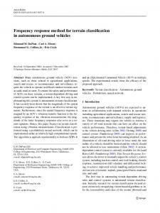
select number of test frequencies that are harmonic. each of the number of frequencies being related by a factor of 2 to test unit
26
1 assemble chosen frequencies into an Excitation Time Record (ETR) that is the Sum of Si-es (SOS) of the chosen frequencies
condition ETR to unit to be tested
excite unit with ETR and simultaneously capture Response Time Record (RTR) with a sample frequency that is octave and harmonicall y related to all of the frequencies within the SOS
process RTR with fast summation transformation equations to estimate frequency components of magnitude and phase for each test frequency
reassemble estimated frequency components to obtain frequency response
FIG. .30
28
30
32
_- 34
36
US 8,150,643 B1 1
2
METHOD OF DETECTING SYSTEM FUNCTION BY MEASURING FREQUENCY RESPONSE
frequencies. The ETR is conditioned to be compatible with the battery. The battery is then excited with the ETR and a Response Time Record (RTR) is captured. The RTR is then synchronized to the ETR and processed by a series of equations to obtain frequency response. In one preferred embodiment, the RTR is processed to obtain estimated frequency components of magnitude and phase for one of the selected frequencies. Processing is repeated to obtain estimated frequency components for each selected frequency. Frequency components are reassembled to obtain an Estimated Time Record (ETR). The ETR is subtracted from the captured RTR to get an error. The error is minimized to achieve the frequency response estimate. Error is minimized using Compensated Synchronous Detection (CSD) using a CSD algorithm, which can be implemented by a neural network. In another preferred embodiment, all excitation frequencies of the SOS are harmonics by powers of two. The sample period likewise is a power of two with all the SOS frequencies. The RTR is rectified relative to a square wave and a 90-degree shifted square wave of one of the SOS frequencies. Integrating the processed RTR results in an "in phase" and "quadrature" sum that is easily processed to yield the magnitude and phase shift of the desired frequency components. Frequency components are assembled to obtain frequency response. The subject method allows a parallel implementation for swept frequency measurements to be made utilizing a composite signal of a single time record that greatly reduces testing time without a significant loss of accuracy.
CROSS-REFERENCE TO RELATED APPLICATIONS This application is a continuation-in-part of U.S. patent application Ser. No. 11/825,629, filed Jul. 5, 2007, now U.S. Pat. No. 7,395,163, issued Jul. 1, 2008, which is a continuation of U.S. patent application Ser. No. 11/313,546, filed Dec. 20, 2005, now abandoned, which claims the benefit of U.S. Provisional Patent Application Nos. 60/637,969, filed Dec. 20, 2004, and 60/724,631, filed Oct. 7, 2005. The disclosure of each of these applications are hereby incorporated by reference in their entirety, including all figures, tables and drawings. STATEMENT REGARDING FEDERALLY SPONSORED RESEARCH OR DEVELOPMENT
5
10
15
20
The subject invention was made with government support under a research project supported by NASA, Grant No. NNA05AC24C. The government has certain rights in this invention. Further, the United States Government has certain rights in this invention pursuant to Contract No. DE-AC0705ID14517 between the United States Department of Energy and Battelle Energy Alliance, LLC.
25
BACKGROUND OF THE INVENTION
30
Electrochemical Impedance Measurement Systems use the Bode analysis technique to characterize an impedance of an electrochemical process. It is a well-established and proven technique. A battery being evaluated is excited with a current that is a single frequency and its response is measured. The process is repeated over a range of frequencies of interest until the spectrum of the impedance is obtained. The method is effective but time consuming, as the process is serial. A parallel approach using band width limited noise as an excitation current can obtain the same information in less time. The system response to the noise is processed via correlation and Fast Fourier Transform (FFT) algorithms and many such responses are averaged. The result is the spectrum of response over the desired frequency range. The averaging of many responses also makes this process somewhat serial. Another technique assembles the current noise waveform from a sum of sinusoids, each at a different frequency. The system response as a time record is acquired and processed with the FFT algorithm. To reduce noise, multiple time records of waveforms are processed and their resultant spectra averaged. This process is also serial. There remains a need for real-time acquisition of battery impedance for control and diagnostics over a limited frequency range. This method of acquisition should be a true parallel approach that uses a single time record of battery response with a duration compatible with a real-time control process. BRIEF SUMMARY OF THE INVENTION The invention involves using a parallel approach to analyze battery impedance or other system functions. A number of frequencies are selected over which the battery is to be tested. These frequencies are assembled into an Excitation Time Record (ETR) that is the Sum of the Sinusoids (SOS) of the frequencies and the length of such periods of the lowest of the
BRIEF DESCRIPTION OF THE SEVERAL VIEWS OF THE DRAWINGS 35
40
45
50
55
60
65
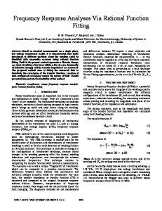
FIG. 1 shows a Filter Ideal Magnitude Response. FIG. 2 shows a Filter Ideal Phase Response. FIG. 3 shows a Filter Uncompensated Synchronous Detected Magnitude Response. FIG. 4 shows a Filter Compensated Synchronous Detection (CSD) Magnitude Response. FIG. 5 shows a Filter CSD Phase Response. FIG. 6 shows a Lumped Parameter Model (LPM). FIG. 7 shows a portion of a Sum of Sines (SOS) signal to LPM, 13 lines, 10 periods. FIG. 8 shows a portion of an LPM time response, 13 lines, 10 periods. FIG. 9 shows an LPM ideal magnitude response, 13 lines, 10 periods. FIG. 10 shows an LPM ideal phase response, 13 lines, 10 periods. FIG. 11 shows an LPM uncompensated magnitude response, 13 lines, 10 periods. FIG. 12 shows an LPM CSD magnitude response, 13 lines, 10 periods. FIG. 13 shows an LPM CSD phase response, 13 lines, 10 periods. FIG. 14 shows aportionofanLPM SOS signal, 25 lines, 10 periods. FIG. 15 shows a portion of an LPM time response, 25 lines, 10 periods. FIG. 16 shows an LPM ideal magnitude response, 25 lines, 10 periods. FIG. 17 shows an LPM ideal phase response, 25 lines, 10 periods. FIG. 18 shows an LPM uncompensated magnitude response, 25 lines, 10 periods.
3
US 8,150,643 B1 4
FIG. 19 shows an LPM CSD magnitude response, 25 lines, FIG. 23. The desired frequencies are assembled as an excitation time record 12 that is a sum of those sinusoids and have 10 periods. a length of several periods of the lowest frequency. The time FIG. 20 shows an LPM CSD phase response, 25 lines, 10 step selected must be compatible with Shannon's sampling periods. FIG. 21 shows a Mean Squared Error (MSE) comparison 5 constraints for the highest frequency component. The individual waveforms should be sine waves of equal amplitude for a low-pass filter frequency response. but alternating signs for a phase shift of 180 degrees between FIG. 22 shows an MSE comparison for detection of LPM the components. Alternating the 180-degree phase shift will impedance. minimize a start-up transient. The Root Mean Square (RMS) FIG. 23 is a flow chart showing a preferred method of the io and the rogue wave peak (sum of the absolute values of all invention. component peaks) of the assembled time record must be FIG. 24A shows a Fast Summation Transformation (EST) compatible with the system being excited and the Data Acquiimpedance spectrum as magnitude vs. frequency. sition System (DAS) that will capture the response. FIG. 24B shows an EST impedance spectrum as phase vs. The Excitation Time Record (ETR), as a current for impedfrequency. FIG. 24C shows an EST impedance spectrum as a Nyquist 15 ance identification or voltage for system function identification, is signal conditioned 14 to be compatible with the Unit plot of imaginary component vs. real component. Under Test (UUT). As part of the signal conditioning, antiFIG. 25A shows an FST impedance spectrum as magnitude aliasing filters ensure that all frequencies generated by the vs. frequency. digital-to-analog conversion process other than the intended FIG. 25B shows an EST impedance spectrum as phase vs. 20 frequencies are suppressed. The UUT is excited 16 by the frequency. ETR and a time record of the UUT response is captured by the FIG. 25C shows an EST impedance spectrum as a Nyquist DAS. The UUT Response Time Record (URTR) is synchroplot of imaginary component vs. real component. nized to, and the same length as, the ETR. FIG. 26A shows an FST impedance spectrum as magnitude A preferred embodiment of the processing of the response vs. frequency. FIG. 26B shows an EST impedance spectrum as phase vs. 25 time record is described below. In order to fit steady-state sinusoidal response assumptions, a preselected number of frequency. data points R at the beginning of the URTR must be discarded. FIG. 26C shows an EST impedance spectrum as a Nyquist In general, the sum of those data points total to a time that is plot of imaginary component vs. real component. larger than the transient response time of the UUT at the front FIG. 27A shows an FST impedance spectrum as magnitude 30 end of the ETR. The UUT corrected time response is referred vs. frequency. to as the CTR. FIG. 27B shows an EST impedance spectrum as phase vs. In order to fit steady-state sinusoidal response assumpfrequency. tions, a preselected number of data points, R, at the beginning FIG. 27C shows an EST impedance spectrum as the of the URTR must be discarded. In general, the sum of those Nyquist plot of imaginary component vs. real component. FIG. 28A shows an FST impedance spectrum as magnitude 35 data points total to a time that is larger than the transient response time of the UUT at the front end of the ETR. The vs. frequency. UUT Corrected Time Response is referred to as the CTR. FIG. 28B shows an EST impedance spectrum as phase vs. The first estimate of components, magnitude, and phase of frequency. the frequency response is made by processing 18 the URTR FIG. 28C shows an EST impedance spectrum as a Nyquist 40 via Equations 3 through 10. It is important that a zero mean be plot of imaginary component vs. real component. established prior to processing with Equations 3 to 10 (see FIG. 29A shows an FST impedance spectrum as magnitude below). vs. frequency. The core of this whole concept is that an estimate of the FIG. 29B shows an EST impedance spectrum as phase vs. UUT Corrected Time Response, the CTR, is made by reasfrequency. FIG. 29C shows an EST impedance spectrum as a Nyquist 45 sembling 20 the CTR using the estimates of the individual frequency components with the same time step and then plot of imaginary component vs. real component. discarding the first R time steps to become the ECTR. The FIG. 30 is a flow chart showing another preferred method difference between the CTR and the ECTR is an error 22 and of the subject invention. minimizing 24 this error will increase the accuracy of the DETAILED DESCRIPTION OF THE INVENTION 50 frequency response estimates. A first approach to minimizing the error between the CTR The method of the subject invention allows for real time and the ECTR is Compensated Synchronous Detection estimation of a battery's impedance spectrum. The shift of a (CSD). The CSD algorithm synthesizes a residual time record battery's impedance spectrum strongly correlates to the of the original time record using the magnitudes of the inhealth of the battery. Therefore, the subject method provides 55 phase and quadrature components for each frequency, except in-situ diagnostics for state-of-health estimation of the bat- the one to be detected. This synthesized residual is then sub tery, which is critical for enhancing the overall application's tracted from the original time record. The resulting compenreliability. The subject method measures a frequency sated time record is processed with synchronous detection response of a unit under test, for example, a battery. The and a new compensated estimate of the response at the detecbattery under test is excited by the sum of sinusoids of a 60 tion frequency is obtained. Since all of the other components number of test frequencies. A response time record is cap- in this compensated time record are suppressed, the error tured, then processed, to obtain estimates of frequency com- from leakage at those other frequencies is less. This process is ponents for each of the number of frequencies. Estimated repeated for each of the frequencies. Assembling the residual frequency components are assembled to achieve a frequency time record and generating the compensated time record are 65 illustrated by Equations 11 and 12 (see below). response. A system function can be identified over a limited number Another approach to minimize the error between the CTR of specific frequencies at step 10 as shown in the flow chart of and the ECTR is to use a neural network. A first estimate of
US 8,150,643 B1
5
6
the component magnitudes and phases is made as described N is the number of points of the response time record for the CSD technique. Those values are stored and the ECTR M is the number of different sinusoids of the excitation is calculated. This signal is then subtracted from the CTR to time record produce a response residual. The synchronous detection is Each component magnitude and phase of the system then performed upon this residual and the component mag- 5 response at all the excitation frequencies can be obtained via the following synchronous detection analysis. This analysis nitudes and phases are again stored. These components are quantifies the response at the k h radian frequency w k with the then used to reconstruct an estimate of the residual signal. "in phase" and "quadrature" response. The analysis incorpoThis estimated residual signal is subtracted from the initial rates a feature of discarding a preselected number of points R residual signal to produce a residual, residual signal. This is 10 at the beginning of the system response in order to meet the then synchronously detected and the loop starts again. This is assumption of steady-state sinusoidal response. Additionally, repeated as many times as desired, each time with the resultfor most applications, prior to processing the data, the mean ant components being stored. The assumption is that there is of the acquired time record should be computed and deleted. a functional relationship between these resultant components The presence of a non-zero mean could corrupt an estimate of and a true system response. A neural network is then used to 15 the lowest frequency component. determine this relationship. The previously stored results In phase: become the test dataset for the neural network. The network has been trained previously on a similar unit and a known ideal response (e.g., battery impedance measured using elec(3) trochemical impedance spectroscopy). The output of the net- 20 K-= 1 iAKsin(&)K(j — OAt+ N —R work is the estimate of the response. j=R+1 A further step of the subject method is to shift the complete O ^M1 set of desired frequencies and to repeat the whole process. L B i sin(o i (j —1)At+ Oouti ) inK)E(& This step couldbe repeated many times with different shifts to develop a high-resolution frequency response that for battery 25 impedance could be comparable to that provided by electro(AKBK 1 (4) [ COS (O inK — OLIt K Sl — chemical impedance spectroscopy. Thus, the subject method N—R 2 j=R+1 can provide capability for both limited frequency response in real-time or high-resolution frequency response not in realcos (2C)K (j —1)At + OinK + QloutK)1 + time for periodic system in-depth diagnostics. 30 AKB' The system of the subject invention is based on the follow , 2 [cos((wk—w;)(j-1)Ot + O inK — @oUt;)i#k=1 ing theoretical design. The Unit Under Test (UUT) is excited with a limited sum of sinusoids, each at a different frequency cOSOA + mi )(j — OAt+ OinK + 0ou01 that is spread over the range of interest. The magnitude, frequency and phase of each sinusoid making up the sum are 35 JJJ known. If a total response of the system is measured via a (5) our
K)
ourK = AKBK cos(OinK — 0outK)
sample data system at an acceptable sample rate and an
adequate duration time record is acquired, then a simple algorithm that uses the known magnitude, frequency and phase of each individual sinusoid will process the single time record. This analysis will obtain the true Bode response at the selected frequencies spread over the range of interest all in parallel. The following synchronous detection analysis is the basis of this simple algorithm. The reference waveform is chosen as a sine, as at time zero everything will be at zero. Equation I gives the relationship for a parallel excitation.
Y'
=
If the time record were infinite, the summation over j would average everything to zero except the final result of Equation 5. The quadrature analysis follows in the same way.
40
Quadrature:
45
N
1
(6)
AKCOS(^K(j-1)At +OinK)
Fqo K = N — R j=R+1 M
M
(1)
fi ,(t) _ YAisin(oit+Oini)
50
=t
^ Y,B
i sin()i (j — 1)At + Oouti j
N
Equation 2 gives the measured sampled data response of the system
Fgo r K = N 1 R
j- R +1
55 M
sin 2m sin( (') K
(2)
1) At+O inK in + ^ ou t + K)1
AKBi
2 [sin(()k+mi)(j-1)Ot +^nK+^our) —
fo. t [j]=YB i sin(o i (j-1)At+Oouti ); j=1:N i#k=1
i=1
60
Where: A, is the amplitude of the i th input sinusoid B, is the amplitude response of the i th output sinusoid w, is the radian frequency of the i th sinusoid At is the time step of data system ^in, is the phase of the i th input sinusoid ^out, is the phase response of the i th output sinusoid
(7)
AKBK [Sin(QloutK - Oin K ) +
Sin((wk —
K— F4o
w i)( j — O At + O inK — 0ou01
A BK sin(OoutK — OinK)
(g)
65
Again, the summation over j for infinite time record averages everything to zero except the final result of Equation 8.
7
US 8,150,643 B1
8
Equations 5 and 8 can be combined to give magnitude and phase for the k`h frequency response.
K
,., I = J." 2 + fq'2 t" = AKBK sin
(9)
between a completely synthesized time record response and the original time record is minimized. The following examples are offered to illustrate the method of the subject invention and should not be construed as lim5 iting.
K
2 (Oin —QloutK)+cos 2 (OinK —QloutK) = AKBK
Example 1
=1
oFout
K
AKBK
K
1 FgO°rK _ = tanout ) —
1
K
sin out — OinK) (^ 2 AKBK COS ,/, 2 (00WK — OinK)
Analytical Testing on a Sum of Sines
(10) 10
The CSD algorithm was evaluated using a simple signal that was assembled from a finite sum of equal amplitude sine waves (Sum of Sines (SOS)) with frequencies distributed 1^ sin(QloutK — OinK) _ Tall ( O o.tK — OinK) logarithmically over a limited range. The objective of the cos(OoutK — OinK) 15 analysis was to assess how well the CSD algorithm could pick out an amplitude for each component. Equations 9 and 10 give the final results for synchronous To check out the concept analytically, a MATLAB® matrix detection. This process is repeated for all M of the excitation calculation computer software code was written that was a sinusoids. As stated, the results depend on the time record logarithmic mix of 5 equal unity amplitude frequencies (50s being infinite in duration. This is not the case and, thus, the 20 5 1 , 5 1.5, 5 2, 52.5 Hz). The acquired time record was set to 10 results are in error by leakage from the other components. periods of the lowest frequency and the time step was set to This error can be reduced without increasing the time record 1/io of the period of the highest frequency. As per Equation 9, using the following algorithm for Compensated Synchronous error-free detection should estimate the amplitude of 0.5 for each component. Table 1 gives an estimate for a first pass or Detection (CSD). The CSD algorithm synthesizes a residual time record of 25 simple synchronous detection and a second pass, the CSD algorithm. The MATLAB® matrix calculation computer the original time record using the magnitudes of the in-phase software code for this analysis is disclosed by Morrison et al., and quadrature components for each frequency except the one 2005, Algorithms as MATLAB Code for Real time Estimato be detected. This synthesized residual is then subtracted from the original time record. The resulting compensated 30 tion of Battery Impedance. time record is then processed with synchronous detection, TABLE 1 and a new compensated estimate of the response at the detection frequency is obtained. Since all of the other components Compensation algorithm analytical results in this compensated time record are suppressed, the error Frequency from leakage at those other frequencies will be less. This 35 process is repeated for each of the frequencies. Assembling a 5.5 51 51.5 525 52 residual time record and generating the compensated time 1st Pass (Simple Synchronous Detection) record are illustrated by Equations 11 and 12. Amplitude
0.5060
Amplitude
0.5004
40 (11)
^M-1 fRK [ 3l
L , (Fpsln(Lgyp ( 3 — 1)Ot) + FQpcos(L)p ( 3 — 1)Ot));
0.5060 0.4975 0.4988 2nd Pass (CSD Algorithm) 0.4998
0.5004
0.5000
0.5008
0.5003
p=1,p#K
j=R+1:N
CJKo 1J f0u 1J JRK1J
Where: is the original time record fRK is the correction time record Cfxout is the compensated time record F, is the estimated in phase amplitude response at the
(12)
f ut
As seen in Table 1 analytically, the compensation tech45 nique does appear to work as the error for the second pass is much reduced. This initial check of the concept was applied to detect amplitude only and not phase detection. The signal is a sum of equal amplitude sine waves being decomposed into the individual components by the algorithm. 50
Example 2 pth
Analytical Testing of a Low-Pass Filter
frequency
F,P is the estimated quadrature amplitude response at the 55 A recursive model of a second order low-pass function was frequency excited with an SOS input signal. The CSD algorithm was wP is the radian frequency of the pth sinusoid then used to estimate the frequency response at each of the At is the time step of the data system specific frequencies making up the SOS. N is the number of points of the output time record A spread of 13 specific frequencies was chosen that were M is the number of different sinusoids of the excitation 60 spaced in 1/4 decade steps starting from 0.1 Hz up to 100 Hz. function Using these frequencies, a mix of equal unity amplitude sine R is the number of points of the output time record that are waves was created. This range of frequencies was picked as discarded research performed at the Idaho National Laboratory with The synchronous detection algorithm described by Equabatteries is typically over this frequency spread. The signal tions 1 through 8 is applied to the compensated time record of 65 was discretized with a time step that was 10% of the period of Equation 12 and better estimates of F p and F P are obtained. the highest frequency. The length of the time record was set at This process can be repeated again until the total difference 10 periods of the lowest frequency.
pth
US 8,150,643 B1 9 A recursive model of a second order Butterworth low-pass function was developed. A center frequency was set at the middle of the SOS frequency spread. A filter response to the SOS input time profile was computed. Finally, the CSD code was developed to estimate the filter frequency response from the time profile generated by the recursive model code. That code is the implementation of Equations 1 through 12. Additionally, the implementation has the ability to discard a number of user-selected points at the beginning of the time profile such that the remaining data better fits the assumption of "steady-state" response. The following 6 figures are MATLABO matrix calculation computer software discrete plots of an ideal frequency response, an uncompensated frequency response, and finally, a compensated frequency response. All 3 have a magnitude plotted against a Log of frequency. FIGS. 1 and 2 are an ideal magnitude and phase response. FIG. 3 is an uncompensated magnitude response, while FIG. 4 is a compensated magnitude response. The improvement seen by comparing the last two figures is clear FIG. 5 is the compensated phase response. Error at the higher frequencies for the compensated result is likely due to processing a small signal at the high frequencies relative to larger signals at the lower frequencies. The net result is that the one-time record yields a limited number of points for both magnitude and phase. This technique shows promise for real-time applications. The MATLABO matrix calculation computer software code for this analysis is disclosed by Morrison et al., 2005, Algorithms as MATLAB Code for Real time Estimation of Battery Impedance. The next approach will apply the concept analytically in an attempt to identify the impedance of a computer model of a battery. Example 3 Analytical Testing of CSD with a Battery Model The CSD algorithm was evaluated analytically via a computer simulation of the detection of the impedance of the Lumped Parameter Model of a battery (LPM) that was developed by the Idaho National Laboratory (INL) (see, FreedomCAR Battery Test Manual, 2003). A computer model for the LPM that will simulate battery voltage response to an arbitrary battery current was also developed at INL by Fenton et al., 2005. The voltage response of the model normalized to the current in the frequency domain will be the battery impedance. The equivalent circuit for the LPM with parameter identification is shown in FIG. 6. The LPM was excited with a current source I rr, that was an SOS, and the CSD algorithm was used to identify the impedance seen looking into the LPM over a limited range of discrete frequencies. It should be noted that the polarity of the voltage response was defined as negative because the SOS excitation current was a discharge (negative relative to impedance). The CSD algorithm was used to obtain the frequency response of the LPM. The CSD response magnitude and phase were compared to the ideal response. Initially, the algorithm failed to match ideal impedance. The response of a battery terminal voltage to a discharge SOS current signal will contain a DC term caused by the DC battery voltage. Synchronous detection of any specific frequency in the response will cause a noise frequency in the resultant spectrum at the frequency being detected, at an amplitude of the product of the DC battery voltage, and an amplitude of the detection signal. That noise amplitude will be large relative to the signal being detected. Averaging enough cycles in the resultant time record will reject this noise. However, for a
10 real-time application, the length of the time record needs to be short and not long. The problem was resolved when the mean was deleted from the prediction response of the LPM. The number of frequency lines was set to 13 and were logarith5 mically spread from 0.01 Hz to 1.0 Hz. The time record was set to 10 periods of the lowest frequency. In the CSD algorithm, no data points were discarded. Table 2 gives analysis specifics with LPM data that is typical for some lithium batteries that INL had recently tested. INL performed the 10 testing per methods in the FreedomCAR Battery Test Manual, 2003. TABLE 2 Representative LPM and Analysis Data
15
20
voc = 3.8 Cp = 666.6667 Coe = 1.6667e+003 Ro = 0.0250 Rp = .0150 M = 13 Dt =.01 N = 100000 F =.01 FF = 10 S =.125
25 NN = 10
At Rest At Rest
Number of frequency lines Time step, sec Total number of points Starting Frequency, Hz Frequency spread in decades Step size (log) over the decades, 8 steps per decade Length of time record in number of periods of lowest frequency
The following 7 figures are the plots of the analysis results. FIG. 7 is the time record of the SOS current signal. FIG. 8 is the time record of the LPM voltage response. FIGS. 9 and 10 are the LPM ideal impedance magnitude and phase. FIGS. 11 and 12 are the uncompensated and the compensated magnitude response. FIG. 13 is the compensated phase response. 35 The number of frequency lines was increased to 25 and everything else was left the same. The following 7 figures illustrate the results. FIG. 14 is the time record of the SOS current signal. FIG. 15 is the time record of the LPM voltage response. FIGS. 16 and 17 are the LPM ideal impedance 40 magnitude and phase. FIGS. 18 and 19 are the uncompensated and the compensated magnitude response. FIG. 20 is the compensated phase response. Additional cases run showed that as the length of the acquired time record in the number of periods of the lowest 45 frequency gets cut back, the number of frequency lines that can be resolved without a big increase in error must be cut back. For example, 5 periods with 25 lines gave terrible results, but 5 periods with 13 lines was fine. These positive results are only analytical. Nevertheless, they offerpromise of 50 positive expected performance when applied to a physical system. All the MATLABO matrix calculation computer codes for this analysis are given by Morrison, 2005, Algorithms as MATLABO Code for Real time Estimation of Battery Impedance. 30
55
Example 4 Neural Network Enhanced Synchronous Detection In order to improve the accuracy of the CSD, studies were conducted upon neural network enhancement of the detection of the individual frequency components of the response of a linear system to an SOS input signal. The concept is very similar to the CSD, with some slight changes and a neural 65 network output layer. For a second order low-pass filter, ordinary synchronous detection performed on the filter response showed a mean squared error (MSE) of 2.6x10 -3 . The com60
US 8,150,643 B1 12
11 pensated synchronous detection technique displayed an MSE of 1.6x10 -3 . The neural network enhanced synchronous detection showed an MSE of 0.2x10 -3 . Results for the lumped parameter model of a lithium ion battery were similar. The theory of neural network enhanced synchronous detection is based on a classical synchronous detection and an inherent error associated with time records of finite length. Given an input signal comprised of a sum of N sinusoids:
estimate would be exact if the time record was infinite, but since it is of finite length, the reconstructed signal is not exactly correct. This may be viewed as containing noise.
Y[i7
=
N ,a,„ sin(&)„ iAt)+j3,,, cos(&)„ At)+r7[iI n
10 where: r l [i]=the noise due to error x(t) _ x(&) t) At —the sample time step n=^ i=the i th position in the acquired time record N=the number of frequency lines the output of the system would be: 15 In the compensated synchronous detection approach, this difference between the actual signal and the reconstructed signal is exploited to filter out all but one of the frequencies N and to increase the accuracy of the measurement (see above). v( t) Y,Y(&)at) In Neural Network Enhanced Synchronous Detection n 20 (NNESD), the approach is slightly different. The premise is that the residual left from subtracting the reconstructed signal from the actual signal still contains some useful information. Being that the input and output are sinusoids, they are assumed to have started at t=-- and continues to t=-. In r[ij=Y[ij—y[ij reality, however, this is not the case. First, the time record of 25 For each frequency of interest, the sine and cosine compothe signal is finite in length; second, it is sampled. Given a nents are detected on the original signal. These are then used sampling frequency of at least the Nyquist frequency (twice to reconstruct the signal and then stored. The reconstructed the highest frequency in the signal), the signal can be reconsignal is then subtracted from the original signal to obtain the structed without error. This does not, however, rectify the residual signal. Synchronous detection is then performed finite time length of the signal. Because of this, errors enter 30 upon this residual signal; once again the sine and cosine into the synchronously detected frequency components. components are used to reconstruct the residual signal and are Synchronous detection involves multiplying the acquired also stored. This second residual signal is then subtracted signal by sines and cosines of the desired frequencies and from the first residual signal. This loop continues until a summing the results, as shown below: sufficient number (M) of sine and cosine responses are 35 obtained for each frequency. Now, the assumption that is made is that there is some functional relationship between 1 a^, = lirni-_ 2i Y[J7sin[&)njOt1 these M responses and the true responses. N
=-i
a u^nuth J\au^ n l^Nu^l^ a u^2^Nu^ n2^ ... ^au^nM^Nu^nM) l3" = li m--
1
Y [J1 cos [ & )n jOtl
The magnitude of a given frequency is obtained as follows: M^,n
2y^^
and the phase may also be obtained as follows:
_ a^
Pin
—Tan 1k &'
where: yU]=the sampled signal a=the sine component of the response for the frequency w„ P —the cosine component of the response for the frequency w„ At —the sample time step Notice that the summations are infinite in length. In application, the summation would be from 0 to the length of the recorded signal. Ifthetimerecordwas infinite, then any errors would cancel out. Since our time record is not infinite, errors remain in the calculated response. It is important to note that an estimate of the original signal can be reconstructed by summing the sine and cosine signals of the different frequencies, where each sine signal is multiplied by its sine response component and each cosine signal is multiplied by its cosine response component. The resulting
40 R^n^ u^, 1(aw,i,R^n i,a^nz,R^nz, ... ,a^„nr,R^„nr)
This functional relationship most likely varies from system to system and also is based upon system operating conditions. To deduce what this relationship is for any system would be 45 time consuming. Instead, a generalized regression neural network is implemented to predict the true response. A Generalized Regression Neural Network (GRNN) is a form of a radial basis neural network suitable for problems involving regression, function estimation, or prediction of a 50 continuous value, Wasserman, 1993, Alpaydin, 2004. This is in contrast to a very similar network, the Probabilistic Neural Network, which is used for classification applications. Unlike multi-layer perceptrons, which require training, a GRNN is constructed from a training set of example inputs and the 55 corresponding outputs. The spread of the radial basis function is used to compute the bias. The spread, in effect, controls the spread of the radial basis function. The example inputs are in the form of an mxn matrix where each of the m rows represents an observation and each of the n columns represents a 60 feature, or parameter. The corresponding example output is an mxl vector. The input is said to be n-dimensional. The network is divided into 2 layers. The first, or input layer, consists of the example inputs. The output layer consists of the example outputs. The network generates its output in the 65 following manner. The geometric distance is calculated between the newly presented input and each of the example inputs in the input layer:
US 8,150,643 B1 13 N 4 = Z (x„ - IW„ ), n=^
This produces a vector of length m. Each element of the vectoris then multiplied by thebias, whichis 0.8326/Spread. The vector then goes through the radial basis function. v =e x
The radial basis function produces an output that gets closer to I as the input gets closer to 0. The resulting vector is a ranking of how close each of the example cases are to the new input. The normalized dot product is then calculated between the vector and the example output vector. This is the network output.
1 M
Y =Y, M
m=,
14 approach, a National Instruments data acquisition and processing system was used along with a custom analog conditioning system. The CSD or NNESD algorithm could be installed directly on the custom analog conditioning system. 5 The system software will be CSD or NNESD rather than Noise Identification of Battery Impedance (NIBI). The NIBI approach would acquire about 100 time records of the battery response to noise current. Clearly, a time record would have to be of a length of multiple periods of the lowest frequency of to interest. The CSD or NNESD approach will acquire one time record of a length of multiple periods (exact number is still to be determined) of the lowest frequency of interest. The excitation signal would be generated analytically with software, 15 as in the NIBI system. The analytical signal would be preconditioned with a digital low-pass filter as in the NIBI system. The CSD or NNESD system may require an analog filterprior to the current driver and after the D/A. This analog filter at the current driver could serve as the prime anti-aliasing filter. 20 This system will use the same bias compensation approach to remove most of the DC battery voltage from the acquired signal. Improved noise rejection and increased sensitivity could be achieved if the voltage sensing were upgraded to full differential via a 4-wire system rather than the 2-wire single25 ended system of the NIBI. An increase in sensitivity will enable a reduction in the level of the excitation signal required. It is anticipated that the sampled voltage will be processed directly with the CSD or NNESD algorithm. It is also anticipated that a system calibration would be done 30 exactly as the NIBI system by measuring the impedance of the test leads to determine any system measurement offset and phase shift. Currently, calibrating the CSD system for magnitude response is done using current shunts in place of a test battery. 35 Multiple shunts encompassing range of response are measured and the resulting data are used to generate a linear regression calibration curve. This technique is also essentially a one-point phase calibration with the shunt, by definition, having zero degrees of phase shift over the frequency 4o range of interest. Since the entire measurement system is a series process, phase shift in the excitation signal, the test object, the detection amplifier or the processing algorithm all look like phase shift. Thus, during shunt calibration, additional multi-point phase calibrations can be obtained by intro45 ducing a calibrated phase shift into each frequency of the SOS excitation signal and the response processed in the CSD algorithm by using the non-phase shifted SOS signal. A multipoint linear regression magnitude calibration, as well as a multi-point linear regression phase calibration, is obtained. 50 The principal attribute of the CSD method is the ability to obtain a limited resolution frequency spectrum of a system function in real time. Resolution of just a dozen frequency lines is traded off to obtain the very desirable feature of real-time response. The CSD system is able to reduce cross55 talk between adjacent frequency lines over and above what would occur with only synchronous detection. Nevertheless, the number of frequency lines in the single time record must be limited. In a particularly preferred embodiment, a user can
The NNESD is based upon the GRNN approach. Analytical testing will provide a preliminary validation of the concept. The NNESD concept was analytically tested on a 2" d order Butterworth filter using the MATLABO matrix calculating computer software BUTTER function and the INL LPM FreedomCAR Battery Test Manual, 2003, Fenton et al., 2005, for the lithium ion battery. An SOS input signal was used for both cases. For the filter, the component frequencies were varied for each run in order to build up a training set with 10 component lines to be detected. The filter was run 100 times and the output and target response was calculated. The data was randomized and half of the data was used to construct the GRNN and the other half was used to verify the network. The mean squared error (MSE) of the predicted value was calculated and the process was repeated 20 times, shuffling the data each time. The results are shown in FIG. 21. The MSE of both the standard synchronous detection and the CSD are also shown for comparison. The MATLABO matrix calculation computer software code used for this analysis is disclosed by Morrison, 2005, Intelligent Self-Evolving Prognostic Fusion. The technique was then tested on the LPM FreedomCAR Battery Test Manual, 2003, Fenton et al., 2005. The input parameters to the model were nominally set as per Table 2 and randomly varied by up to 5% each run for 100 runs to generate the dataset. The number of lines, frequency spread and time step were held as per Table 2. The same training and testing scheme that was outlined above was used. The results are shown in FIG. 22. The MATLABO matrix calculation computer software code used for this analysis is given in Morrison, 2005, Intelligent Self-Evolving Prognostic Fusion. This limited analytical validation has shown that the NNESD concept will significantly reduce the error in the estimate of the frequency components of a given system response signal. This concept allows a parallel implementachoose to increase resolution at the expense of increased tion for swept frequency measurements to be made by utiliz- 6o response time with either operation. The limited number of ing a composite signal of a single time record that greatly frequency lines in the SOS is adhered to in a single time reduces testing time without a significant loss of accuracy. record. However, for either operation additional time records Conclusions are run with each frequency shifted by a shift factor and the The physical validation of the CSD or NNESD concept additional spectra acquired are interleaved to obtain an overwill rely heavily on work performed by W. Albrecht in his 65 all higher resolution spectrum. Thus, a user can make a custhesis research: `Battery Complex Impedance Identification tom trade-off of spectrum resolution against response time for with Random Signal Techniques," Albrecht, 2005. In this an application.
US 8,150,643 B1 15
16
The CSD system processes the system response of the SOS In Equation 3, the signal has been rectified relative to a sine excitation via repeated synchronous detection acting on a wave of that frequency and all the sample values are totaled residual signal whereby cross-talk contributors have been up. subtracted out. An alternative embodiment of the method of detecting system function of the subject invention, as shown in the flow chart of FIG. 30, uses a fast summation algorithm () N -1 to process the system response of the SOS excitation at step 27r 2n mI =VPEsi 32. In the Fast Summation Transformation (EST) embodi\ Nn+o ) -VPE sl \Nn+O) 0 ment, all the frequencies of the SOS are harmonics by powers 1-2 of two at step 26. Additionally, the sample period is also a power of two with all the SOS frequencies at step 32. Instead 10 of multiplying the acquired time record by the sine and the In Equation 4, the signal has been rectified relative to the cosine of each frequency, the SOS is simply rectified relative cosine wave of that frequency and again the samples are to the square wave and the 90-degree shifted square wave of totaled up. Observe that rectification simply involves changthe desired frequency. When the samples of that processed time record are summed, all the octave-related harmonics, 15 ing the sign of the sample values relative to the sine wave or other than the frequency of interest will always sum to zero. cosine wave timing. The resulting "In Phase" and "Quadrature" sums can be easily processed to yield the magnitude and phase shift of the desired frequency component at step 34. (4) M2 = The EST algorithm can be used to estimate a battery imped20 N N ance spectrum at step 36. The excitation Sum of Sines (SOS) q- q- N- 1 / 2n l / 2n l 2n signal formation at steps 26, 28, 30, the methodology to apply VP sinl N n + ^ - VP ^ sinl N n + o + VP ^ Sinl N n+0) \ J \ f n n=34 it as a current signal to a test battery and the capture of the n=4 battery voltage response time record at step 32 is almost identical to the CSD approach. However, the difference is, if (5) N-1 27r the SOS excitation time record contains only sine waves 25 ffi1 = VP 2z n COSO + Cosl N n sino^ I Sinl whose frequencies are all related by octave and harmonics, and the sample time is also octave and harmonically related, then if that captured time record is "rectified" relative to one 2 7r 2 7r VP E I S n)cosl + cosl n)sinO) of the SOS frequencies at step 34, when that transformed time \ 1 \ 1 1 n-2\ record is summed, it will contain only battery response infor- 30 mation relative to that frequency. To identify a specific battery N frequency response in the SOS signal, the response time MI = VPCOSQI E I sinl N n)) - record is square wave rectified with a phase relationship relaI sinl N n)) + \ \ tive to a sine wave of that frequency at step 36. Then, all the n= _\ points in the time record of that transformed signal are simply Kl totaled up and normalized to the number of periods of that 35 frequency present in the SOS signal. This result becomes a N numerical parameter ml . The process is performed again VPsino (Cos( 7n)) — n)) except the rectification square wave phase is relative to the cos L L n n=N of the frequency of interest. This other result becomes another K2 numerical parameter mz . For all the other frequencies, except 40 the one of interest, all the samples of those sine waves of the N (6) transformed record will always total to zero. The amplitude n sino — and phase response of that frequency are obtained as per the tn2=VP N N following relationships. Equation I represents the sampled signal component at a specific frequency that is to be 34_1 detected. The amplitude, V, and phase, ^ are the desired 45 VP E I Sinl N n cosO + cosl N n sino) + information. \ 1 1 ^ \ \ 1 n= (Cos(N
^ Si
n COSO+ Cos(
N-1 VP sinl N n+ ^^ = VP SinI N n)COSO + VP COSI N n)sino l
11
l
11
l
11
(^)
50
Where: V, is the amplitude response of the frequency of interest N is the number of samples over a period of the frequency 55 of interest
^ is the phase response of the frequency of interest n is the discrete time index In Equation 1, N must be constrained as 109 2 (N) must be an integer greater than 1. Additionally, the frequency of interest 60 is given as:
1 f NAt
Where: At is the sample period.
27r
VP E I S
n=3 4 l l
M2
N / / I sinl
= VPCOSO
0 \ \
11
N n)) 11
27r
N n)COSO + Cosl N n)sino) l
11 11 N / / / / 3^ 1 I sinl N n)) + E I sinl N n)) + \ \
11
\ \
11
n=4 n=34 ----------------------------------------------------------------------K3 N
VP sino
/ \ \
N
I Cost Nn))
- 31 I cost Nn)) + E I cost Nn)) 11 n=4 \ \ 11 n=34 \ \ 11 K4
(2)
Note that the parameters Kl , Kz, K3, K4 are known for each 65 frequency and ra , mz are the numerical result of the rectifying algorithm for each frequency. Then, the magnitude and phase at each frequency can be obtained as follows:
US 8,150,643 B1 17 m i = VpcosOK i + VpsinOK 2
mi
=
K i ,
Kz
i
_
K3 ,
K4
1
M mz = VpcosOK3 +Vpsin^K4 K
VpcosO^= ^
Vpsino
VpsinO - C t
(7)
1S
given as:
5
K 2 K3 -KiK4
K3
Ki
K2 K3 - K i K4 '
Let: Vp cos ^= C2
Vpcoso
K
K i K4 ¢ K 2 K3 '
=
18 The sine waveform of the rectification function with zeros
mz
K i K4 - KzK3
VP ;C2 + Cz ' then: =tan
0,
n=0
1,
0 < n < 2
0,
n = 2
Rs(n) =
(11)
n
(g) 10
Ci
-1,
N 2